
Related Manuals for edc DT 550


Summary of Contents for edc DT 550
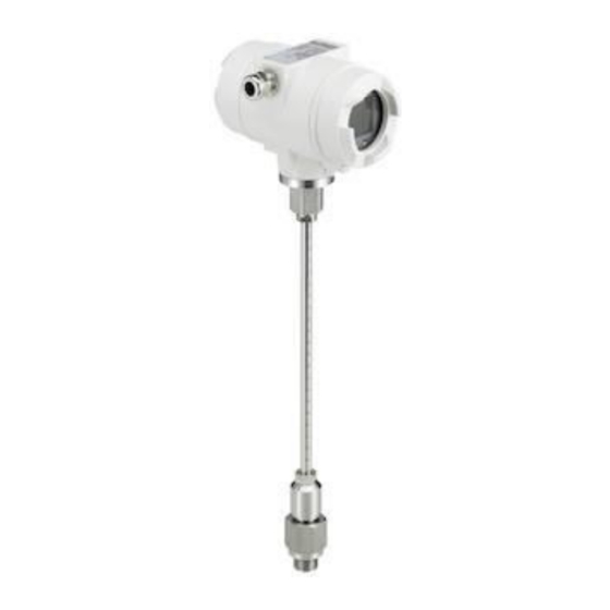
- Page 1 EN - English Instruction manual Flow Sensor DT 550 DT 550 Rev1.0 May20 Page 1 of 50...
-
Page 2: Foreword
Foreword Dear customer, thank you very much for deciding in favour of the DT 550. Please read this installation and operation manual carefully before mounting and initiating the device and follow our advice. A riskless operation and a correct functioning of the... -
Page 3: Table Of Contents
6.3.2 Spot drilling collar with ball valve ..................21 Installation of the Sensor ......................22 6.4.1 Mounting DT 550 onto the ball valve ................. 22 Alignment Display (Housing) ....................23 Tightening torques ........................23 Connection diagram ........................24 Cable glands - clamping ranges ..................... 24 Connector pin assignment ...................... - Page 4 8.3.5.3 Display / Touch ......................44 8.3.6 Advanced ........................... 44 8.3.7 4 -20mA ..........................45 8.3.8 DT 550 Info ........................47 MBus ............................48 8.4.1 Change of communication settings ................... 48 8.4.2 Coding VIF (Value Information Field) ................49 8.4.3 Default Settings communication ..................
-
Page 5: Pictograms And Symbols
Note! Possible hazard As a consequence of incorrect handling: possible personal injury or damage Important! Additional notes, information, tips As a consequence of incorrect handling: Disadvantages in operation and maintenance, no danger DT 550 Rev1.0 May20 Page 5 of 50... -
Page 6: Safety Instructions
Regional and national regulations respectively, have to be observed in addition to this instruction manual if necessary. This instruction manual must be available at any time at the operation site of the DT 550. Ensure that the DT 550 operates within the permissible and listed limits on the nameplate. -
Page 7: Intended Use
The instrument described in this manual is exclusively to use for measuring the thermal mass flow of gases. At the same time, the gas temperature is measured too. The DT 550 can be configured for measuring a predetermined range of pure gases or of gas mixtures. -
Page 8: Technical Data
Screw in thread: Material: Housing aluminum die cast, probe stainless steel1,4571 Protection class IP67 * Reference conditions for Temperature and pressure can be freely set, standard conditions are 0 ° and 1013 mbar. DT 550 Rev1.0 May20 Page 8 of 50... -
Page 9: Signal Circuits
< 500 Ohm • Vin 12-36Vdc 4.1.3 Pulse • Galvanically isolated (dry contact) • Passive: 48Vdc , 500 mA • Max. pulse output freq. 50Hz 4.1.4 Alarm • Galvanically isolated • Max. 48Vdc, 500mA DT 550 Rev1.0 May20 Page 9 of 50... -
Page 10: Measuring Range Flow Dt 550
Measuring range Measuring range flow DT 550 The flow-/consumption sensor DT 550 is available in 4 different versions: • Low Speed max. measuring range of 50 m/s • Standard max. measuring range of 92,7 m/s • Max–Version max. measuring range of 185.0 m/s •... -
Page 11: Maximum Flow Ranges "Low Speed
383,8 397,9 409,3 247,0 64,2 479,5 441,0 749,8 474,6 441,0 457,2 470,3 283,8 Referred to DIN 1945 / ISO 1217 (20°C, 1000mbar) and compressed air. Referred to DIN 1343: 0°C, 1013,25 mbar DT 550 Rev1.0 May20 Page 11 of 50... - Page 12 88454,9 91706,5 94341,5 56920,6 1000,0 118752,2 109203,6 185667,6 117518,1 109203,6 113217,9 116471,0 70272,3 Referred to DIN 1945 / ISO 1217 (20°C, 1000mbar) and compressed air. Referred to DIN 1343: 0°C, 1013,25 mbar DT 550 Rev1.0 May20 Page 12 of 50...
-
Page 13: Measuring Range "Standard Version
711,5 736,8 758,9 457,9 64,2 889,1 817,6 1390,0 879,8 817,6 846,7 872,0 526,1 Referred to DIN 1945 / ISO 1217 (20°C, 1000mbar) and compressed air. Referred to DIN 1343: 0°C, 1013,25 mbar DT 550 Rev1.0 May20 Page 13 of 50... - Page 14 163995,2 169831,2 174909,1 105530,6 1000,0 220166,6 202463,2 344215,1 217862,8 202463,2 209668,2 215937,1 130284,7 Referred to DIN 1945 / ISO 1217 (20°C, 1000mbar) and compressed air. Referred to DIN 1343: 0°C, 1013,25 mbar DT 550 Rev1.0 May20 Page 14 of 50...
-
Page 15: Measuring Range „Max Version
1420,0 1472,2 1514,5 913,7 64,2 1774,3 1631,7 2774,1 1755,9 1631,7 1691,6 1740,2 1050,0 Referred to DIN 1945 / ISO 1217 (20°C, 1000mbar) and compressed air. Referred to DIN 1343: 0°C, 1013,25 mbar DT 550 Rev1.0 May20 Page 15 of 50... - Page 16 327282,7 339313,7 349063,4 210605,9 1000,0 439383,1 404052,7 686970,6 434817,4 404052,7 418905,8 430942,5 260007,2 Referred to DIN 1945 / ISO 1217 (20°C, 1000mbar) and compressed air. Referred to DIN 1343: 0°C, 1013,25 mbar DT 550 Rev1.0 May20 Page 16 of 50...
-
Page 17: Measuring Range "High Speed Version
1719,3 1782,5 1833,7 1106,4 64,2 2148,4 1975,6 3359,0 2126,1 1975,6 2048,3 2107,1 1271,3 Referred to DIN 1945 / ISO 1217 (20°C, 1000mbar) and compressed air. Referred to DIN 1343: 0°C, 1013,25 mbar DT 550 Rev1.0 May20 Page 17 of 50... - Page 18 396278,4 410844,6 422649,7 255003,8 1000,0 532009,9 489231,3 831791,3 526481,5 489232,6 507215,6 521789,8 314819,5 Referred to DIN 1945 / ISO 1217 (20°C, 1000mbar) and compressed air. Referred to DIN 1343: 0°C, 1013,25 mbar DT 550 Rev1.0 May20 Page 18 of 50...
-
Page 19: Dimensions
Dimension Dimensions Dimension DT 550 138 (max) Ex version (max) 156 (max) 132 (max) (max) (max) Sensor lenght L [mm] H [mm] DT 550 Rev1.0 May20 Page 19 of 50... -
Page 20: Installation
The values represent the min. lengths. In case the min. inlet / outlet runs could not be ensured, it must be expected to get increased or significant deviations of the measurement values. DT 550 Rev1.0 May20 Page 20 of 50... -
Page 21: Installation Dt 550
6.3.2 Spot drilling collar with ball valve In case the system could not be shut down, means to be set depressurized, there could be used the spot drilling collar and drilling jig to drill through the ball valve. DT 550 Rev1.0 May20 Page 21 of 50... -
Page 22: Installation Of The Sensor
Installation Installation of the Sensor 6.4.1 Mounting DT 550 onto the ball valve • Assembly is carried out by inserting the connection thread with gasket. (G1/2“ thread, SW 32) into the connection piece (ball valve). The sensor has be tighten by hand as far as possible and then tighten with stipulated torque of 25-30 Nm. -
Page 23: Alignment Display (Housing)
Installation Alignment Display (Housing) The sensor housing DT 550 can be turned in both directions, max. 345 °. For this purpose, the housing-connecting nut must be opened. The housing can be rotated to the desired position, a bigger rotation angle is prevented by internal stop pins. -
Page 24: Connection Diagram
Standard version with 1x analogue output (not galvanically isolated) Option Board 4-20mA I (4-20mA) I (4-20mA) Main Board Version with option board 2x analogue outputs galvanically isolated Option Board MBus MBUS Main Board Version with option board MBus DT 550 Rev1.0 May20 Page 24 of 50... - Page 25 Direction input I- Active** I+ Active ** I- Active ** I+ Active ** MBus MBus * Outputs are galvanically isolated. ** The Current outputs, X5 and X6, are optional.(Active and passive version available). DT 550 Rev1.0 May20 Page 25 of 50...
-
Page 26: Wire Connection
If the sensor placed at the end oft he Modbus system a termination is required. Therfore the enclosed 120R resistor ist o be connected at Pin 1 and Pin 3 of connector „X2“ Main Board 120R DT 550 Rev1.0 May20 Page 26 of 50... -
Page 27: Modbus Tcp (Ethernet) Optional Poe
Data LINES: 1,2 und 3,4 PoE LINES: 5,6 und 7,8 M12 x 1 Connection cable: Cat 6. *PoE: Power over Ethernet 7.3.5 Pulse Output Main Board Potentialfreier Schaltkontakt Max. 48Vdc , 500mA DT 550 Rev1.0 May20 Page 27 of 50... -
Page 28: Operation Dt 550
Operation DT 550 Remark: In version with display only The operation of the DT 550 are carried out by 2 optical keys through the glass cover Thus, the DT 550 can be operated from the outside without opening the cap. -
Page 29: Main Menu (Home)
Operation Main menu (Home) 8.1.1 Intialization After switching on the DT 550 the initialized screen is displayed followed by the main menu. Flow Sensor Main menu *** VA 550 *** Gas / Status Info HW Version Modbus ID Page-No. SW Version “... -
Page 30: Settings
Selection of a menu item or to change a value “ is done with the key >“, a final move to the chosen menu item or takeover of the value change needs the confirmation by pressing the “OK” DT 550 Rev1.0 May20 Page 30 of 50... -
Page 31: Sensor Setup
>“, select the respective position and activate the position with the "OK" button. “ >“ By pressing the position value is incremented by 1. Complete with "OK" activate next number position. „OK“. Confirming entry by pressing DT 550 Rev1.0 May20 Page 31 of 50... -
Page 32: Input / Change Consumption Counter
In case the quantity of units selectable are not presentable on one page, pleas move to next “<<“ page by pressing Confirm selection by pressing 2x “OK“. Procedure for all 4 measurement variables is analogous. DT 550 Rev1.0 May20 Page 32 of 50... -
Page 33: Definition Of The Reference Conditions
1. Complete with "OK" activate next number position. Procedure for changing the reference temperature is the same. DT 550 Rev1.0 May20 Page 33 of 50 Under point "Filtertime" together with the appropriate "Filter Grade"... - Page 34 Setup → Sensor Setup→ Advanced → AV-Time The time period for averaging can be entered here. Input values of -1440 1 [minutes] are possible. For average values, see display window 3 + 4 DT 550 Rev1.0 May20 Page 34 of 50...
-
Page 35: Setting Of Zeropoint And Low-Flow Cut Off
“Reset“ By selection of all settings for “ZeroPnt“ and. “CutOff“ are reset. 1,03 “ >“ Menu item to be select with button “OK“ confirm the reset with “Back“ Leave menu with button DT 550 Rev1.0 May20 Page 35 of 50... -
Page 36: Modbus Rtu
Operation 8.3.2 Modbus RTU The Flow sensors DT 550 comes with a Modbus RTU Interface. Before commissioning the sensor the communication parameters • Modbus ID, Baud rate, Parity und Stop bit must be set in order to ensure the communication with the Modbus master. -
Page 37: Modbus Tcp (Optional)
8.3.3 Modbus TCP (Optional) 8.3.3.1 Setup The Flow sensors DT 550 comes optional with a Modbus TCP Interface (HW Interface:M12 x 1 X-coded connector). Device supports with this option the Modbus TCP protocol for communication with SCADA systems. TCP port is set to 502 by default. Port can be changed at the sensor or using PC Service Software Modbus device address (Unit Identifier) can be set in the range of 1- 255. -
Page 38: Network Settings Static Ip
"OK" key. Change the values with the ">" key, and accept the values with the "OK" key. Procedure for "Subnet" "Gateway" analogous. “Save“ Store the settings by DT 550 Rev1.0 May20 Page 38 of 50... -
Page 39: Modbus Tcp Settings
(Little Endian) and "CDAB" (Middle Endian) Saving the changes by pressing "Save", “>“ therefore select it with key and then confirm it with "OK". Reset to the default settings by activating "Set to Default"- DT 550 Rev1.0 May20 Page 39 of 50... -
Page 40: Modbus Settings (2001
1180 Float Flow in Ncfm 1189 1188 Float 1197 1196 Float Flow in kg/h Flow in kg/min 1205 1204 Float Flow in kg/s 1213 1212 Float Flow in kW 1221 1220 Float DT 550 Rev1.0 May20 Page 40 of 50... - Page 41 Remark: • For RD400 / RD500 / Handheld devices - Modbus Sensor Datatype „ Data Type R4-32“ match with „Data Type Float“ • For more additional Modbus values please refer to DT5xx_Modbus_RTU_Slave_Installation_1.04_EN.doc DT 550 Rev1.0 May20 Page 41 of 50...
-
Page 42: Pulse /Alarm
3000000 Table 1 Maximum flow for pulse output Entering pulse values that are not allow a presentation to the full scale value, are not allowed. Entries are discarded and error message displayed. DT 550 Rev1.0 May20 Page 42 of 50... -
Page 43: User Setup
Language → → Settings UserSetup Language Currently 4 languages have been implemented and could be selected with button “>“. Change of language by confirming with “OK”. “back”. Leaving the menu with button DT 550 Rev1.0 May20 Page 43 of 50... -
Page 44: Display / Touch
10s. To do this, use the "OK" button to enter the operating menu during this period 8.3.6 Advanced Settings → Advanced “Factory Reset“ By pressing the sensor is set back to the factory settings. DT 550 Rev1.0 May20 Page 44 of 50... -
Page 45: -20Ma
“OK“ and confirm selection by pressing → Settings → 4-20mA Channel 1 The 4-20 mA Analogue output of the Sensor DT 550 can be individually adjusted. It is possible to assign following values “Temperature“, “Velocity“ and “Flow“ to the channel CH 1. - Page 46 Leaving the menu with “Back“. Channel 1:0…max. speed [m/s] Remark: Default setting DT 550 for analogue output is Default settings for DT550 with option board analogue output Channel 1:0…max. speed [m/s] Channel 2: -20°C … 100°C] For max.
-
Page 47: Dt 550 Info
Operation 8.3.8 DT 550 Info → → Setup Sensor Setup Info Here you get a brief description of the sensor data incl. the calibration data. 92,7 m/s 600m³/h Under Details, you are able to see in addition the Run Time: 2d 21h 23m 12s calibration conditions. -
Page 48: Mbus
Operation MBus 8.4.1 Change of communication settings The communication settings Primary-address and baud rate could be changed directly at the sensor, in case sensor has a display, or with the EDC Service software (Order code EDC-SS). → Settings M-Bus →... -
Page 49: Coding Vif (Value Information Field)
Consumption [m³] Value 2 with [Unit]*: Flow [m³/h] Value 3 with [Unit]*: Gas temperature [°C] *All Values could be changed / preset in production or with EDC Service software (Order code EDC-SS) DT 550 Rev1.0 May20 Page 49 of 50... -
Page 50: Supplementary Documentation
Supplementary Documentation Supplementary Documentation • Supplementary Documentation for Ex-Version: Flow / Consumption Sensor DT 550 Ex / DT 570 Ex - Ex-Documentation DT 550 Rev1.0 May20 Page 50 of 50...
Need help?
Do you have a question about the DT 550 and is the answer not in the manual?
Questions and answers