Table of Contents
Advertisement
Quick Links
La Marche Manufacturing Company | www.lamarchemfg.com
MODBUS SCADA Interface
for DCES and ARBS with S2A-225C
Option 21Q
106 Bradrock Dr. Des Plaines, IL 60018-19671
Tel: 847 299 1188
Fax: 847 299 3061
Setup Instructions
This manual is only valid for DCES AND ARBS units
equipped with the S2A-383S-2X00 communications card
and 225C software version P225C7001_050819
Instruction Drawing Number: P25-LOPT21Q-DCES-225C-1
CPN 140620
Revision A00
Rev. Date: 05/19
ECN: 21824-2
Advertisement
Table of Contents

Subscribe to Our Youtube Channel
Summary of Contents for Lamarche Option 21Q
- Page 1 La Marche Manufacturing Company | www.lamarchemfg.com MODBUS SCADA Interface for DCES and ARBS with S2A-225C Option 21Q Setup Instructions This manual is only valid for DCES AND ARBS units equipped with the S2A-383S-2X00 communications card and 225C software version P225C7001_050819 106 Bradrock Dr.
- Page 2 Default Settings The LaMarche Communications Card is shipped with the following default settings; Port: RS232 Baud Rate: 9600 Data Bits: 8 Stop Bits: 1 Parity: None Board Configuration The communications card may be configured for RS232, RS485 or TCP communications.
- Page 3 RS232 & RS485 Serial Applications To configure the card for Serial applications you need to configure the board’s dipswitches and set the Address, Baud Rate and Parity as required in the customer calibration mode. TCP/IP Applications To configure the card for TCP/IP applications you need to configure the boards dipswitches and confirm the Address = 1, Baud Rate = 9600 and Parity = NONE in the customer calibration mode.
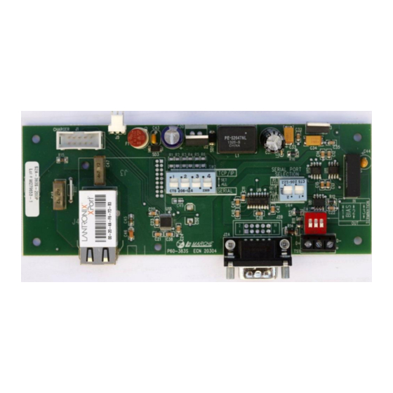
- Page 4 To assign the desire IP settings press the Assign IP button on the Toolbar. This will bring up the following screen: The Device Identification is located on the device itself as described in the dialog text above. An example of the Lantronix device is pictured below.
- Page 5 This dialog presents a choice between assigning an IP dynamically which would allow the device to operate on a network with a DHCP server however it is recommended that a specific IP address be assigned so it can be referenced directly on a SCADA Network. Selecting “Assign a specific IP address”...
- Page 6 Pressing Assign will start the process of programming the device to the new IP Settings. A progress bar and Status will appear indicating a successful operation as shown below: Pressing Finish will complete the IP setting change process. The DeviceInstaller Application can now be closed.
- Page 7 LaMarche ARBS Modbus Implementation Supported Modbus Types Supported Modbus Function Codes 02 -- Read Discrete Input Registers 03 – Read Holding Registers 04 – Read Input Registers 02 - Discrete Inputs Address Name/Description 10000 DC1 Low Voltage Alarm Indicator (FAILURE=1)
- Page 8 04 – Input Registers Address Description, Units Scale Factor Max Set Voltage (MAXV), Volts (3.0vpc * Cells) 30005 Upper Limit For BT1 & BT2 Low Voltage Alarm Settings DCA – DC Current, 30006...
Need help?
Do you have a question about the Option 21Q and is the answer not in the manual?
Questions and answers