
Subscribe to Our Youtube Channel
Related Manuals for CSA XLC 400 Series


Summary of Contents for CSA XLC 400 Series
- Page 1 XLC 470 CSA waterworks line Altitude automatic control valve Mod. XLC 470 For further information please consult us at: www.comeval.es...
- Page 2 This manual will provide you with the information to properly install and maintain CSA automatic control valves XLC 400 series. The contents and the procedure are intended for technicians in charge of CSA valves only, prior to a theoretical and practical training by CSA qualified personnel only.
-
Page 3: Table Of Contents
XLC 470 Contents Description - - - - - - - - - - - - - - - - - - - - - - - - - - - - - - - - - - - - - - - - - - - - - - - - - - - - - - - - - - - 4 Handling and storage - - - - - - - - - - - - - - - - - - - - - - - - - - - - - - - - - - - - - - - - - - - - - - - - - - - - 5 Installation - - - - - - - - - - - - - - - - - - - - - - - - - - - - - - - - - - - - - - - - - - - - - - - - - - - - - - - - - - - - 6 Set up - - - - - - - - - - - - - - - - - - - - - - - - - - - - - - - - - - - - - - - - - - - - - - - - - - - - - - -- - - - - - - - - 7... -
Page 4: Description
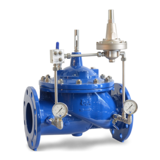
XLC 470 Description (ref. picture 1 on page 4) The pilot operated control valve XLC 400 series Mod. 470 is designed to automatically maintain a constant level of a tank, regardless of upstream pressure variations, through a high sensitivity pilot connected to the static pressure (5) of the tank itself. -
Page 5: Handling And Storage
XLC 470 Handling and storage Lifting the valve improperly may damage it and the equipments around. It is mandatory not to fasten the valve around the circuit, fittings, pipes, solenoids or position indicators. Valves must be lifted only by cables, chains, located around the body, through the flanges holes or eyebolts. During hoisting always consider that the center of mass depends on the circuitry and pilots installed. -
Page 6: Installation
CSA control valves to allow for maintenance. The operating fluid must be free of air, air valves (CSA Mod. FOX 3F AS combination anti- slam) should be installed upstream . This to avoid the accumulation of air pockets during working conditions and allow air discharge during pipe filling and commissioning. - Page 7 XLC 470 The connection to the pilot’s pressure port should always sense the static pressure of the tank, do not use the inlet out outlet pipe from the tank difference pressure generated by the valve during pressure sustaining/relief function will produce a thrust proportional to the pressure itself. Anchorage blocks and way of preventing valve’s movement or shifting need to be taken into account.
-
Page 8: Set Up
Always leave enough time for the system to balance, in case of doubts and problems allow for some flow through the by-pass to stabilize the line and call CSA technical support. Make sure the isolation ball valves of the circuitry (2-3-4-5) are fully open ... - Page 9 Valves epoxy painted FBT Maintenance CSA automatic control valves XLC 400 series have been designed with a sturdy and reliable construction to minimize servicing and possible malfunctioning. However we recommend to inspect them at least twice per year releasing the air accumulated inside the bonnet and checking the strainer inside the GR.I.F.O, if present, or placed as a separate entity in the circuitry.
-
Page 10: Maintenance Of Mpz Pilot
XLC 470 MPZ – Altitude control pilot The altitude control pilot is a diaphragm operated valve, spring loaded and direct acting, that can be installed basically in any position. The function is to reduce and stabilize the downstream pressure value taken on the sensing port, regardless of flow rate and upstream pressure fluctuations, usually being the static pressure of the tank... - Page 11 3- Take out the upper part with the cover (2), the spring (7) , the spring guide (6). Do not separate the cover (2) from the upper part (15) unless strictly required, to do so loose and unscrew the screws (24) 4- With a monkey wrench remove the self clocking nut (8) and pull out the upper flat (9) 5- Remove the diaphragm (10) inspect the surface, clean it and replace if necessary or in case of scratches, damages...
-
Page 12: Maintenance Of Grifo
XLC 410 GR.I.F.O. 3 – 3/8″ PN 25 GR.I.F.O.-3 G3/8 PN25 VELOCITA' CHIUSURA VELOCITA' APERTURA CLOSING SPEED OPENING SPEED SALSOMAGGIORE TERME(PR) TEL.+39 0524 523978 www.csasrl.it ORIFIZIO CALIBRATO ADJUSTABLE ORIFICE The “GR.I.F.O.” (Integrated Group Filter Orifices) is a unit flow control device that includes all the necessary functions, needed for the proper regulation and stability of the main valve. - Page 13 XLC 470 - the intervention also called reaction speed regulator* (4) of the main valve, and the opening (3) and closing (2) speed regulators* of the valve’s main chamber, independent one from the other, obtained by us fine adjustment needle valves. - replaceable check valves placed upstream of every regulator to limit the flow and control the acceleration during the valve opening and closing.
-
Page 14: Visual Position Indicator
DIsassembly The CSA position indicator is a sturdy and solid item not subject to maintenance, in case of frost and unexpected and accidental impact it may break. For the disassembly simply hold the lower part (2) and unscrew the upper part (1). -
Page 15: Maintenance Of General Xlc 400 Valve Body
XLC 470 Interventions on the main XLC 400 valve Component Material Body GJS 450-10 or GJS 500-7 GJS 450-10 or GJS 500-7 Position indicator St. steel/Ni-plated brass Pressure outlet tap AISI 316 Upper flat o-ring NBR/EPDM/Viton Obturator o-ring NBR/EPDM/Viton Indicator stem AISI 303 Main shaft AISI 303/AISI 316... -
Page 16: Troubleshooting
XLC 470 Problems solving Problem Cause Solution The main valve doesn’t The sealing seat is ruined Replace the sealing seat close The ball valves of the circuit are Open the ball valves closed There is no pressure inside the Check the pressure coming into main chamber the circuit The diaphragm is damaged ( see the... - Page 17 XLC 470 1) Checking the diaphragm In order to verify if the diaphragm has suffered any damage simply proceed as follows: a) slowly close the upstream and downstream gate valves; b) close all the ball valves of the circuit; c) completely open the air vent valve from the position indicator, if the latter is not present the fitting of the isolation valve on the chamber;...
- Page 18 XLC 470 The clogging can be located between the seat and obturator if the indication rod is in closed position and the flow continues, or between the sealing seat and cap if the valve does not reach the complete opening. Before proceeding to dismantling the cover, it is suggested to do some manual opening and closing operations putting the main chamber under pressure and discharging it.
- Page 19 XLC 470 Disassembly As mentioned before make sure that the gate valves upstream and downstream of the valves have been properly closed and set tight. Relieve the pressure of the main chamber simply by closing the isolation valves of the circuit and opening one of its fittings.
- Page 20 XLC 470 Reassembly To reassemble do the reverse of the disassembly procedure positioning the main shaft back into the grip along with all the pieces. It is very important not to forget the O-Ring (21) and to set the nut tight (10) to assure a proper torque between the diaphragm and the plane gasket. Please be extremely careful with this step because a nut not properly tight may engender movements making the mobile block unstable, therefore affecting the valve’s performance.
- Page 21 XLC 470 We reserve the right to incorporate our latest design and material changes without notice or obligation. Design features, materials of construction and dimensional data, as described in this manual, are provided for your information only. For further information please consult us at: www.comeval.es...
Need help?
Do you have a question about the XLC 400 Series and is the answer not in the manual?
Questions and answers