Table of Contents
Advertisement
Quick Links
Advertisement
Table of Contents

Subscribe to Our Youtube Channel
Related Manuals for Vision & Control TZB10-IR850-P-24V


Summary of Contents for Vision & Control TZB10-IR850-P-24V
- Page 1 VISION & CONTROL Instructions for Use Instructions for Use TZB10-IR850-P-24V TZB10-IR850-P-24V Telecentric Lights, Telecentric Lights, Luminous colour: Infrared - 850 nm Luminous colour: Infrared - 850 nm 999.995.419.10-en-1.6 © Vision & Control GmbH 2021...
- Page 2 Impress Publisher / Manufacturer Vision & Control GmbH Mittelbergstraße 16 98527 Suhl, Germany Telephone: +49 (0) 3681 7974-0 Telefax: +49 (0) 3681 7974-33 www.vision-control.com Name of the document 999.995.419.10-en-1.6 Date of first issue 2020-12-15 Date modified 2021-10-22 Copyright © Vision & Control GmbH 2021 Copyright It is forbidden to pass this document on to third parties, reproduce and communicate its contents in as far as this has not been expressly authorized.
- Page 3 Validity These instructions for use are valid for the following device: Device Order no. TZB10-IR850-P-24V 1-33-249 Product Identification Designation Description Telecentric Lights Luminous field diameter in mm IR850 Luminous colour: Infrared - 850 nm Power LED 24 V DC operating voltage, with integrated lighting controller ©...
- Page 4 TZB10-IR850-P-24V 999.995.419.10-en-1.6 © Vision & Control GmbH 2021...
-
Page 5: Table Of Contents
TZB10-IR850-P-24V Table of Contents TABLE OF CONTENTS 1 Information about the Instructions of Use..........7 1.1 Intended Use....................7 1.2 Improper Use....................8 1.3 Qualified Personnel..................8 1.4 Warranty and Liability...................9 2 Safety......................10 2.1 Presentation of Safety Instructions.............10 2.2 Safe Handling of the Device..............11 3 Scope of Delivery and Accessories............ - Page 6 TZB10-IR850-P-24V 999.995.419.10-en-1.6 © Vision & Control GmbH 2021...
-
Page 7: Information About The Instructions Of Use
TZB10-IR850-P-24V Information about the Instructions of Use 1 INFORMATION ABOUT THE INSTRUCTIONS OF This document contains technical information, important instructions for correct installation, commissioning and use, as well as product information which were up-to-date at the time of going to press. -
Page 8: Improper Use
TZB10-IR850-P-24V Information about the Instructions of Use 1.2 Improper Use All unintended use and all device-related activities not described in these instructions of use is to be deemed as unauthorised misuse outside the legal limits of indemnity of the manufacturer. -
Page 9: Warranty And Liability
TZB10-IR850-P-24V Information about the Instructions of Use 1.4 Warranty and Liability The contents of this document have been checked carefully and correspond to current legislation and best practise at the time of going to press. However, the manufacturer shall not be liable for any damage arising from the use of this edition of the manual, and rejects any warranty derived therefrom. -
Page 10: Safety
TZB10-IR850-P-24V Safety 2 SAFETY 2.1 Presentation of Safety Instructions Each safety instruction is introduced by a key word and colour highlighted. The key word indicates the degree of danger. The danger and its cause are described, and then the measures to prevent conceivable consequences of the danger. -
Page 11: Safe Handling Of The Device
TZB10-IR850-P-24V Safety 2.2 Safe Handling of the Device Read the following applicable safety instructions carefully and completely. Follow the instructions for your own safety, the safety of other people, and to avoid damage to the device and the connected technical equipment. Hazards going beyond the general safety instructions are referred to separately at the relevant points in this manual. -
Page 12: Scope Of Delivery And Accessories
3.1 Scope of Delivery Designation Quantity Device TZB10-IR850-P-24V Covering cap TZB10 aperture kit Instructions for Use TZB10-IR850-P-24V 3.2 Accessories Lens holder Designation Description Order no. Lens Holder d35.5 Holder for telecentric lenses and 2-90-124 lightings with 35.5 mm clamping... - Page 13 TZB10-IR850-P-24V Scope of Delivery and Accessories TZB10 aperture kit Designation Description Order no. TZB10 aperture kit 3 screw-in apertures with a diameter 1-10-078 of 2.5 mm, 3.3 mm and 5.4 mm DIN rail power supplies Designation Description Order no. Power supply...
- Page 14 TZB10-IR850-P-24V Scope of Delivery and Accessories Connection cable M8-4-pin, straight plug, 5A, 30V Designation Description Order no. Cable-M8-4p-5A- Connection cable with 4-pin M8 socket 1-11-611 straight-1m and open cable end with wire-end ferrules, 4 x 0.5 mm², 5A, 30V, PUR,...
-
Page 15: Device Description
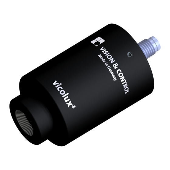
TZB10-IR850-P-24V Device Description 4 DEVICE DESCRIPTION 4.1 Device Views Image 1: Device view Casing Light-emitting surface Identification plate Note screw-in depth Mounting surface with mounting holes Connector M8-4pin © Vision & Control GmbH 2021 999.995.419.10-en-1.6... -
Page 16: Notices On The Device
TZB10-IR850-P-24V Device Description 4.2 Notices on the device Following instructions are provided on the device: Type plate Type: TZB10-XXXX-P-24V SN.: XXXXXXXX Image 2: Type plate Device designation Serial number Notice Screw-in depth screw-in depth max. 7mm Image 3: Notice Screw-in depth 999.995.419.10-en-1.6... -
Page 17: Technical Data
TZB10-IR850-P-24V Technical Data 5 TECHNICAL DATA 5.1 General Parameters Parameter Characteristic Housing material Aluminium, black anodised Optical material Glass Housing dimensions Length: 54 mm without connector Diameter max.: 35.5 mm Dimensions light-emitting Diameter: 11.5 mm surface Connector Male connector, M8, 4-pin... -
Page 18: Electrical Parameters
TZB10-IR850-P-24V Technical Data 5.2 Electrical Parameters Parameter Operating voltage U 19 V 24 V 29 V Power consumption at U = 24 V DC 0.4 W 0.5 W 0.6 W Switch input Input voltage OFF 2.0 V ON/OFF Input current OFF 0 mA 0.2 mA... -
Page 19: Conditions For Operation, Storage And Transport
TZB10-IR850-P-24V Technical Data Spectral Emission Wavelength [nm] Image 4: Spectral emission 5.4 Conditions for Operation, Storage and Transport Observe the specified ambient conditions when transporting and storing the device. For accessories, connected devices and components observe the specific information in the associated instructions for use. -
Page 20: Technical Drawings
TZB10-IR850-P-24V Technical Data 5.5 Technical Drawings Image 5: Technical Drawings (dimensions in mm) 999.995.419.10-en-1.6 © Vision & Control GmbH 2021... -
Page 21: Commissioning
TZB10-IR850-P-24V Commissioning 6 COMMISSIONING NOTICE Installation and connection operations may only be performed in the off and de-energised state. 6.1 Unpacking 1. Lift the cardboard, together with the device, out of the carton. 2. Fold out the tucked in sides on the bottom of the cardboard. The film loosens and forms an insertion pocket. -
Page 22: Mounting The Accessories
TZB10-IR850-P-24V Commissioning 6.3 Mounting the accessories Mount the Lens Holder 2.) 3.) 1. Loosen the M5 hexagon nuts (a) on the lens holder. 2. Slide the lens holder to the desired location on the lighting. 3. Tighten the M5 hexagon nuts alternately hand-tight in small steps. - Page 23 TZB10-IR850-P-24V Commissioning Mount the Deflection Mirror 2.) 3.) 1. Loosen the M3 threaded pins (a) of the deflection mirror. 2. Attach the deflection mirror on the lighting. Rotate the mirror (b) to the desired position. 3. Tighten the M3 thread pins alternately hand-tight in small steps.
-
Page 24: Connecting
TZB10-IR850-P-24V Commissioning 6.4 Connecting NOTICE Cable damage • Comply with the specified minimum bending radius. • Cables must generally be mounted with a strain relief clamp. • Use cables corresponding to the specification (see data sheet). 6.4.1 Pin assignment Use the M8 connector to connect the device according to the pin assignment. -
Page 25: Operation
TZB10-IR850-P-24V Operation 7 OPERATION CAUTION Physiological effects by flashing lights • Working under flashing lights can cause effects such as headache, nausea, or epileptic seizures. • Avoid exposure to certain kinds of flashing lights or stroboscopes. • Wear protective goggles. -
Page 26: Operating Modes
TZB10-IR850-P-24V Operation 7.2 Operating Modes The integrated controller supports the following operating modes: Continuous operation The lighting is switched on by setting the ON/OFF signal after the delay time t Resetting the ON/OFF signal turns off the lighting. Switching operation The switching operation is carried out by continuously setting and resetting the switching signal ON/OFF. -
Page 27: Maintenance And Service
TZB10-IR850-P-24V Maintenance and Service 8 MAINTENANCE AND SERVICE 8.1 Maintenance The device is maintenance-free. Depending on the operating environment, it may have to be cleaned. The housing can be cleaned according to the conditions applicable to the given protection class. -
Page 28: Service
TZB10-IR850-P-24V Maintenance and Service 8.2 Service Technical Support Please contact our technical support if you have any technical questions concerning our products. We will be glad to be of service: Monday to Thursday 8:00 to 17:00, and Friday 8:00 to 15:00. -
Page 29: Disposal
TZB10-IR850-P-24V Disposal 9 DISPOSAL The device and its accessories and packaging must be sent to environmentally compatible recycling. Do not throw electrical devices or tools into the household waste! According to European Directive 2012/19/EU on waste electrical and electronic equipment and its implementation in national law, unusable electric tools must be collected separately, and sent to environmentally compatible recycling. - Page 30 TZB10-IR850-P-24V 999.995.419.10-en-1.6 © Vision & Control GmbH 2021...
-
Page 31: Eu Declaration Of Conformity
D-98527 Suhl, Germany Representative: Dr. Jürgen Geffe, Managing director We, Vision & Control GmbH Suhl, declare that the product described below – Designation: TZB10-IR850-P-24V – Order no.: 1-33-249 has been manufactured in accordance with the following standards and normative documents: •... - Page 32 Vision & Control GmbH Mittelbergstraße 16 98527 Suhl, Germany Telephone +49 (0) 3681 7974-0 Telefax: +49 (0) 3681 7974-33 Vision & Control GmbH...
Need help?
Do you have a question about the TZB10-IR850-P-24V and is the answer not in the manual?
Questions and answers