
Summary of Contents for Clarke CIS666
- Page 1 MINI GARDEN SHED MODEL NO: CIS666 PART NO: 3503579 ASSEMBLY INSTRUCTIONS ORIGINAL INSTRUCTIONS GC0122...
-
Page 2: Safety Warnings
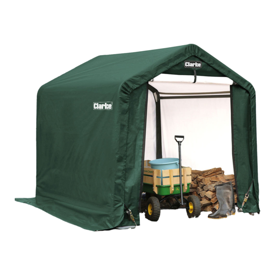
When erected, the CIS666 Shed will be of the dimensions shown on page 4. The product weight is 20.65 kg (unpacked) 22.4 kg (packed). - Page 3 POSITIONING AND INSTALLATION OF THE SHED POSITIONING THE SHED This shed is a temporary structure and is not recommended as a permanent building. It is designed to offer protection from sun, rain, light snow, tree sap and bird droppings etc. It is not designed to shelter equipment from excessively high winds or heavy snow.
- Page 4 A supply of fresh air through the doorway will at least partly remove this issue. For long term storage of moisture sensitive belongings in all weathers, the use of a dehumidifier may be required, such as those in the CLARKE range. A suitable extension lead to a locally available power supply will be required.
-
Page 5: Component Parts List
COMPONENT PARTS LIST Parts & Service: 020 8988 7400 / E-mail: Parts@clarkeinternational.com or Service@clarkeinternational.com... - Page 6 ASSEMBLY WARNING: DO NOT PLACE THE PRODUCT UNDER TREES FROM WHICH HARD FRUIT SUCH AS APPLES, WALNUTS OR HEAVY PINE CONES, ETC., MAY FALL. KEEP CHILDREN AWAY DURING ASSEMBLY. THIS PRODUCT CONTAINS SMALL PARTS WHICH CAN BE SWALLOWED BY CHILDREN. DO NOT ATTEMPT TO ASSEMBLE THE PRODUCT IF ANY PARTS ARE MISSING.
- Page 7 STEP 1: ASSEMBLING THE ROOF FRAME 1. Select a suitable location for the shed. The layout of the roof parts is shown. Note: The three connectors are different and individually numbered. When using them, ensure the welded socket for the cross rail is below the bend.
- Page 8 NOTE: Be sure that all tubes are fully inserted. Use a rubber mallet if necessary. When using the connectors, be sure to remove the protective caps first. STEP 2: ATTACHING THE LEGS There are 4 corner legs for the whole shed. These comprise the extension poles 2 (with dimple) and the bent corner legs (6).
- Page 9 4. Repeat the same procedure on the opposite side. STEP 3 ATTACHING THE BOTTOM CROSS-RAIL 1. Connect the cross rail male union (4) and cross rail with punched hole (5) together. Attach the bottom cross rail connectors (4/5) to the legs and cover the joints with the cross rail clamps (10).
- Page 10 STEP 4: SQUARE AND ANCHOR THE FRAME WARNING: SERIOUS INJURY TO PERSONS OR PROPERTY COULD RESULT IF THE SHED IS NOT SECURELY ANCHORED, WITH EITHER THE GROUND ANCHORS SUPPLIED OR IF SITED ON CONCRETE OR TARMAC USE SUITABLE SUBSTANTIAL GROUND ANCHOR BOLTS. 1.
- Page 11 STEP 5 ANCHORING THE FRAME 1. Four anchors are provided to secure the shed. They are to be installed around the bent corner legs at each corner of the shed. 2. Screw the anchor head into the ground. 3. Insert the cable (19) through the eyelets of the anchor (18) and the bent corner leg (6).
- Page 12 1. Thread the webbing strap though the spindle of the ratchet. Raise and lower the handle several times to wind the strap onto the spindle as shown above. 2. Locate the top part of the front door panel (17) near the 3-way peak connector (7).
- Page 13 3. Attach the other two corners of the front door panel (17) to the 3-way side connectors (8/9) in the same way 4. Insert the S-hook of the ratchet into the hole of the bent corner leg (6). Pump the ratchet handle repeatedly to tighten the strap.
- Page 14 1. Lay the cover on the ground next to the frame. Make sure that the ends with the black straps are alongside the front door/back panels (16/17) and the tube sleeves are facing upwards. 2. Stretch the roof cover (15) over the shed frame and make sure it is centred on the frame.
- Page 15 Repeat the same procedure for the opposite side of the roof. Check and ensure all bottom cross rail connectors (4,5) are level and horizontal, and are all the same height from the ground. Tighten all nuts and bolts at this stage. Fasten the black straps at the four corners with the ratchet tie-down (11).
- Page 16 This can take the form of an additional Auger Securing Set GA2 (already supplied with CLARKE Instant Garages), which can add greater security for exposed, windy locations. Alternatively the Easy Hook Anchoring System GHA2, can be used to provide greater security on soft ground.
Need help?
Do you have a question about the CIS666 and is the answer not in the manual?
Questions and answers