
Related Manuals for Lean ROBOTIQ AX Series


Summary of Contents for Lean ROBOTIQ AX Series
- Page 1 ROBOTIQ PALLETIZING SOLUTION AX Series Original Notice © 2022 Robotiq Inc. Robotiq Palletizing Solution - AX Series for Universal Robots robot iq.com | leanrobot ics.org Instruction Manual...
-
Page 2: Table Of Contents
Revisions 1. General Presentation 1.1. Palletizing Solution Components 1.2. Object Picking 1.3. Palletizing Operation Diagrams 2. Safety 2.1. Disclaimer 2.2. Intended Use 2.3. Warnings, Risk Assessment and Final Application 3. Installation 3.1. Scope of Delivery 3.2. Required Tools and Equipment 3.3. - Page 3 7.1. Linear Axis 7.2. Fasteners 7.3. AirPick Vacuum Gripper 7.4. Cleaning 7.5. Solution Storage 8. Spare Parts, Kits and Accessories 9. Troubleshooting 9.1. Palletizing Solution (except the AirPick Gripper) 9.2. AirPick Vacuum Gripper 10. Warranty 11. Harmonized Standards 11.1. Applied Standards 12.
- Page 4 Palletizing Solution - Instruction Manual...
-
Page 5: Revisions
Revisions Robotiq may modify this product without notice, when necessary, due to product improvements, modifications or changes in specifications. If such modification is made, the manual will also be revised, see revision information. See the latest version of this manual online at: support.robotiq.com. 2022/01/04 Added script functions Updated Installation on Universal Robots e-Series section... - Page 6 2021/03/29 Update of the Software section: label orientation option added. Update of the Specifications section Update of the Installation section (Robot configurations) 2020/12/16 Update of the safety section Update of the installation section Update of the specifications section 2020/11/30 Update of the Installation section. 2020/11/25 Initial release...
- Page 7 Copyright © 2020-2022 Robotiq Inc. All rights reserved. This manual and the product it describes are protected by the Copyright Act of Canada, by laws of other countries, and by international treaties, and therefore may not be reproduced in whole or in part, whether for sale or not, without prior written consent from Robotiq.
-
Page 8: General Presentation
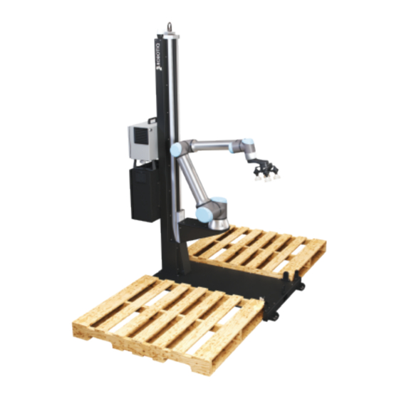
1 . General Presentation The terms " Palletizer" , " Palletizing Solution" , " Robotiq Palletizing Solution" , " Solution" and " AX Series" used in this manual all refer to the AX Series Robotiq Palletizing Solution. The AX Robotiq Palletizing Solution is a hardware and software solution already connected and ready to install. - Page 9 Info The following section presents the key features of the Robotiq Palletizing Solution and must not be considered as appropriate to the operation of the Solution. Each feature is detailed in the appropriate section. 1 .1 .1 . Base and Column The Robotiq Palletizing Solution is composed of a base and a column on which all the components that are necessary to the good operation of the Solution are attached.
- Page 10 Fig. 1-1: Robotiq AirPick Gripper 1 .1 .7. Suction Cup System A Robotiq Suction Cup System can be installed directly under the Vacuum Gripper. Each Robotiq Suction Cup System includes a bracket, a manifold, air nodes, port plugs, bumpers, tubing and additional suction cups. Fig.
- Page 11 1 .1 .8. Extra Reach Gripper Bracket The extra reach gripper bracket is included in the Solution to extend the AirPick Gripper of 200 mm from the robot tool flange. This way, the Robotiq Palletizing Solution will be able to palletize boxes on large size pallets. Please refer to the Extra Reach Bracket section for more details about the limitations of the extension bracket Fig.
-
Page 12: Object Picking
1 .2. Object Picking The AirPick Gripper allows: 1. Main unit suction cup 2. Auxiliary system with multiple suction cups Warning Object picking causes the compression of the suction cup(s) , which can result in pinching points between the gripper and the load. -
Page 13: Palletizing Operation Diagrams
1 .3. Palletizing Operation Diagrams The following diagrams explain the logical operation of the Palletizing Solution based on the operator's actions, as well as responses such as signals, pallet and box sensor behaviors, etc. Please refer to the Status Lights section for further information about light states. - Page 14 Palletizing Solution - Instruction Manual...
-
Page 15: Safety
2. Safety 2.1 . Disclaimer The intent of this section is to provide general guidelines for safe use of the Robotiq Palletizing Solution, always follow local regulations. The installer is responsible for the safe installation and commissioning of the Palletizing Solution. Robotiq accepts no liability for damage, injury or any legal responsibility incurred directly or indirectly from the use of this product. -
Page 16: Intended Use
2.2. Intended Use The Robotiq Palletizing Solution is specifically designed for palletization. Warning Only use the application in its original condition without unauthorised modifications. Warning Only use the application if it is in perfect technical condition. Warning The emergency stop function is intended for use in emergency conditions and not for normal condition stop. Info The Solution is intended to be used with a UR10 or UR10e from Universal Robots. -
Page 17: Warnings, Risk Assessment And Final Application
2.3. Warnings, Risk Assessment and Final Application Warning The operator must have read and understood all of the instructions in the following manual before operating the Robotiq Palletizing Solution. Caution Any use of the Palletizing Solution in non-compliance with these warnings is deemed inappropriate and may cause injury or damage. - Page 18 Warning When the robot is not moving, the collaborative collision detection is disabled. If the linear axis moves, it can hurt people with the robot. Warning Depending on the supply sources, when an emergency stop (e-Stop) button is pressed, the following consequences may occur.
- Page 19 Emergency stop mode when the emergency stop button is pressed. All components of the system will undergo stop category 1 transitioning to stop category 0. Robot Linear Axis Operation mode Speed Speed Force (N) Power (W) Force (N) Power (W) (mm/s) (mm/s) Normal mode...
- Page 20 Fig. 2-1: Safety Logical Schema Warning In the event of a collision or after an emergency stop, an inspection of the solution must be performed before resuming the use of the machine. Special attention must be given to the carriage assembly, the linear axis, the cable management system, and the gripper components.
- Page 21 Palletizing Solution - Instruction Manual...
-
Page 22: Installation
3. Installation The following subsections will guide you through the installation and general setup of your Robotiq Palletizing Solution. Info Before installing: Read and understand the safety instructions related to the Palletizing Solution. Verify your package according to the scope of delivery and your order. Make sure to have the required parts, equipment and tools listed in Scope of delivery. -
Page 23: Scope Of Delivery
Warning Make sure to follow all the safety rules and regulations of your workplace while using the Robotiq Palletizing Solution. Always wear all recommended personal protective equipment in accordance with your workplace's safety standards, including: Safety glasses; Hearing protection; Hard hats; Steel-toe boots Always use proper safety precautions when working with tools that contain sharp edges, pinching surfaces, or generate heat. -
Page 24: Required Tools And Equipment
3.2. Required Tools and Equipment The following tools are required to install the Palletizing solution. Included: 12.7 mm (1/2 in) concrete drill bit (for use with hammer drill) 19 mm (3/4 in) socket, 10 mm (3/8 in) drive size 17 mm socket, 10 mm (3/8 in) drive size 2 mm hex key 3 mm hex key 4 mm hex key... -
Page 25: Environmental And Operating Conditions
3.3. Environmental and Operating Conditions Conditions Value Minimum storage/transit temperature -25°C [-13°F] Maximum storage/transit 60°C [140°F] temperature Minimum operating temperature 0°C [32°F] Maximum operating temperature 50°C [122°F] Humidity (non-condensing) 20-80% RH, non-condensing Food/ Clean room/ Intrisic Safety (IS) Dust: Affect the time between maintenance Dust and water Water : No Free from corrosive liquids or gases... -
Page 26: Mounting And Installation
3.3.1 . AirPick Gripper Air Supply Compressed air must be supplied to the Vacuum Gripper according to the technical specifications. For maintenance and other purposes, it is recommended to install a lockout valve before connecting to the product. The air supply tubing must be connected and disconnected to, or from, the inlet port, only when the line is depressurized. - Page 27 1. Remove the top panel and the four (4) sides of the crate by unscrewing the screws that hold them into place. 2. Cut all the strapping material that retains the components, and take all cardboard boxes out of the crate. 3.
- Page 28 6. Lift the foot base, unscrew the piece of wood under the foot base. Remove the piece of wood and descend the Solution slowly and carefully (see the picture below). Palletizing Solution - Instruction Manual...
- Page 29 7. Position the column vertically. Use the lift point to rotate the column. Caution Be careful not to pinch the cables. If necessary, secure them before lifting and placing the column on the base.
- Page 30 8. Lift and place the column onto the base. Info A hook is present at the top of the column. Use it to lift the column. 9. Secure the column on the base using the four (4) M10 screws provided. Tighten to a torque of 50 Nm. Caution Make sure to have all components in hand before discarding the crate and packaging.
- Page 31 3.4.3. Moving and Positioning the Solution Warning Failure to properly secure and install the equipment can result in material damage and bodily injury. In addition, note that the warranty will not cover material damage resulting from an installation that did not comply with the instructions found in this manual.
- Page 32 3.4.4. Mechanical and Electrical Installation A minimum of two people is recommended to execute these steps. Robot Installation Info A UR10 or UR10e cobot is required for the installation. The cobot is not included in the Robotiq Palletizing solution. For robot installation, few cables need to be wired. The figure below resumes the identification of the column holes. Palletizing Solution - Instruction Manual...
- Page 33 1. Place the robot on the robot base plate so its power cable is oriented towards the linear axis. Align properly with the two dowel pins (already installed on the robot base), and secure the robot using four (4) M8 screws and Belleville washers. The torque value required is 20 Nm.
- Page 34 Base Cover Plate 1. Remove the cover plate that will allow the cable management. Palletizing Solution - Instruction Manual...
- Page 35 Universal Robots Controller Installation 1. Remove the four screws on the top of the linear axis controller. 2. Place the UR controller on top of the linear axis controller and secure it with the four screws you previously removed. Caution Do NOT plug the UR controller power cable into UR controller .
- Page 36 Power Cables Connections 1. Plug the power cable output of the linear axis controller into the UR controller. 2. Plug the robot power cable into the UR controller. 3. Connect the Teach Pendant to the UR controller. Palletizing Solution - Instruction Manual...
- Page 37 4. Plug the UR controller power cable into the linear axis controller. Pass the cable through the hole #2. Then, continue to chan- nel the cable through the column and the base and bring it out from the other extremity of the base. Info The safety signals wires sticking out of the linear axis controller are inputs only.
- Page 38 Pallet Sensors and Base Cables Routing 1. Connect the pallet sensors. The cables are identified for each side. Make sure to connect each pair of cables correctly. 2. Bring out the air tube and the box sensor cable from the bottom of the column and continue to channel it until you bring it out from the other extremity of the base (through the rectangle hole).
- Page 39 3. Position the robot so that the wrist is on the outside left side of the base like shown in the figure below. 4. Move the robot so the robot tool flange is parallel to the ground: change the feature reference to Base and modify the tool position like the following: RX=0°, RY= 180°, RZ=0°.
- Page 40 AirPick Vacuum Gripper Installation To be able to mount the AirPick Gripper, its accessories, as well as the cable routing system, power on the robot and rotate the joints, as described in the table below. Then, shutdown the robot Joint Position Base -180°...
- Page 41 If the two or four suction cups bracket is needed: 1. Align the flat surface on the manifold with the shoulder of the vacuum generator. 2. Secure the manifold by inserting screws and tooth lock washers in a cross pattern to properly compress the O-ring of the generator.
- Page 42 To finish the installation, change the robot position. Refer to the table below: Joint Position Base -180° Shoulder -155° Elbow -60° Wrist 1 -80° Wrist 2 90° Wrist 3 -90° 1. Attach the Igus triflex® R Series (TRE.40B) cable routing system to the robot, as illustrated in the figure below: Using a 5 mm hex key, secure the elbow collar assembly (larger collar) to the arm.
- Page 43 2. If you use the extra reach bracket, make sure to first run the coupling cable through the second hole of the bracket. 3. Connect the coupling cable to the connector visible at the end of the cable carrier. 4. Install Igus R-Lock clips at the end of the cable carrier before clipping it in the bracket. It will ensure the good functioning of the cable management system.
- Page 44 Caution Use dry and filtered air only. Follow the ISO 8573-1, class 3.4.3 standard. We recommend using a local pressure regulator with a filter and air dryer. 9. Use the spiral cable sleeve to keep the air tube and the coupling cable together. 10.
- Page 45 4. Pass the other extremity of the cable through the hole under the UR controller and connect it into the Ethernet/USB con- verter cable that is already connected. Info Follow cable management good practices. You can either drill a hole in the hole plug or use a grommet (not included). Fig.
- Page 46 3. Connect the white, green and bare wires to the Robotiq RS-485 signal converter as shown in the figure below. Also, connect the red (24V) and black (0V) wires to the terminal blocks of the robot controller. Fig. 3-2: Vacuum Gripper wiring to robot controller 4.
- Page 47 Box Sensor 1. Run the box sensor’s cable through a hole under the robot controller. Connect the brown (24V), blue (0V) and black (digital input) wires to corresponding connectors in terminal blocks. Info Follow the good practices of the cable management. You can use the plate under the controller and use a grommet (not included).
- Page 48 Anchoring the Solution Warning: The transport, lifting, and moving of the Palletizing Solution should be done by qualified professionals. Failure to do so may result to machine damage, bodily injury or death. Warning The Solution must only be installed and anchored by qualified staff. If you use the anchors provided with the Solution, it should be installed in 28 MPa [4000 psi] undamaged concrete (minimum).
- Page 49 1. Position the Solution at its final position. Caution Make sure your layout is good and that all distances are respected. See the Appendix section. 2. Drill the six (6) holes with the provided drill bit. 3. If necessary, level the solution using shims. 4.
-
Page 50: Other Grippers
3.5. Other Grippers It is possible to use a gripper other than the AirPick Vacuum Gripper. If another gripper is used, it is important to validate that its shape is within the gripper model used for the collision detection algorithm of the software. If your gripper does not fit the following models, it can still work, but Robotiq does not guarantee that there will be no collision. - Page 51 If a TCP offset is added in the X and/or Y direction, it is considered that an extra reach bracket is used. A rectangular prism is then added at the end of the bracket, according to the rules mentioned above. Bracket representation Height Width...
-
Page 52: Installation For Universal Robots
3.6. Installation for Universal Robots The table below shows which Robotiq software to use with your Universal Robots’ controller. Please refer to the URCap Package section for the installation of the UR software packages for the Palletizing Solution. Info For CB-Series robots, the controller must have been produced after september 2019 (serial number > 2019301732) to be able to be installed on the Solution. - Page 53 On e-Series Universal Robots Make sure that your PolyScope version is up- to-date and that your Universal Robots con- troller is compatible with the Palletizing solu- tion URCap package. Go to support.robotiq.com, and select the Universal Robots brand. Select Palletizing Solution. Click on Software →...
- Page 54 Once the files are selected, tap the Open but- ton. Tap the Restart button to complete the URCap installation. By doing so, you accept the license agreement detailed in the URCap information textbox. On CB-Series Universal Robots Make sure that your PolyScope version is up-to-date and that your Universal Robots controller is compatible with the Palletizing URCap package.
- Page 55 Tap the plus (+) button to add the URCaps package. Open the URCaps. Restart PolyScope to complete the URCap installation.By doing so, you accept the License Agreement that is detailed in the URCap Information text box (see below for the License Agreement). When PolyScope reopens, the ActiveDrive toolbar will appear on the screen.
- Page 56 3.7.2. Uninstalling URCap Package On e-Series Universal Robots On the teach pendant, tap the triple bar icon. Tap Settings. Select System in the navigation pane on the left. Select URCaps. In the Active URCaps box, select the URCap to uninstall. Tap the minus (-) button to uninstall the URCap.
- Page 57 On CB-Series Universal Robots Go to Setup Robot. Tap URCaps Setup. In the Active URCaps box, tap the URCap to unin- stall. Tap the minus (-) button to uninstall the URCap. Restart PolyScope to complete the uninstallation process.
-
Page 58: Robot Configurations
3.8. Robot Configurations Info Some configurations must be done in the Safety section of the Installation tab, to ensure the proper use of the solution. 3.8.1 . Joint Limits Some joint limits must be configured. For e-Series: 1. Tap Installation→ Safety → Joint Limits 2. - Page 59 For CB-Series: 1. Tap Installation→ Safety → Joint Limits → Position range 2. Then, unlock the section with the proper password and change the values. The minimum and maximum values for the Elbow will be -167° and 0°. The minimum and maximum values for the Wrist 3 will be -270° and 270°. 3.8.2.
- Page 60 For CB-Series Universal Robots: 1. Tap Installation→ Safety → Safety I/O 2. Then, unlock the section with the proper password and set the Output Signal config_out[0], config_out[1] at System Emer- gency Stopped. Palletizing Solution - Instruction Manual...
-
Page 61: License Agreement
3.9. License Agreement END-USER LICENSE AGREEMENT YOU SHOULD CAREFULLY READ THE FOLLOWING AGREEMENT BEFORE USING THE Software (as this term is hereinafter defined). Using the Software indicates your acceptance of the agreement. If you do not agree with it, you are not authorized to use the Software. - Page 62 Such modifications and upgrades of the Software shall be installed by the End-User itself by consulting the Licensor’s Web- site http://robotiq.com/ where a link to proceed to such installation will be made available thereof. A new version of the Soft- ware shall not be covered by this Section 4 but shall require that a new End-User Software License Agreement be entered into between the Licensor and the End-User.
- Page 63 failures and furnish him with information, screenshots and try to reproduce such bugs, defects or failures upon Licensor’s demand. 12. Expiration and Termination. The Licensor may terminate this Agreement for default by the End-User. This Agreement will also be automatically terminated upon the election of such by the Licensor or the official launch of the Software, whichever event comes first.
-
Page 64: Operation
4. Operation 4.1 . Starting Up After the mechanical and electrical installation, follow these steps: 1. Make sure you have installed the URCaps. Please refer to the Installing URCap Package section 2. Configure the TCP. Use the proper values depending on if you use the extra reach bracket or not. 3. - Page 65 Color and Condition status Cause or action needed (troubleshooting for e-Series) signal type The robot has been started and needs time to boot up (Polyscope has not loaded yet) Make sure your Ethernet/USB adapter is properly connected: the LED on the Ethernet adapter should be The linear axis controller (PLC) is unable to Make sure the Ethernet cable between the PLC and communicate with the Robot controller (UR).
- Page 66 Color and Condition status Cause or action needed (troubleshooting for e-Series) signal type The pallet is complete and the system is idle; BLUE Place a new pallet Fast blink The pallet is not detected and the system is idle. The linear axis is activated and brake is released;...
-
Page 67: Software
5. Software 5.1 . Installation on e-Series Universal Robots Caution To ensure normal operation, make sure the Copilot license dongle remains connected at all times. 1. Connect the license dongle to the USB hub in the UR controller. Make sure your Copilot license is activated: a. - Page 68 Warning Activating the Limit height for Palletizer program node option does not limit the linear axis range outside of the Palletizer node. Therefore, caution must be observed when operating the linear axis with the ActiveDrive toolbar or the Linear Axis move node. 3.
- Page 69 5.1 .1 . Palletizer Node Before you start programing your features, make sure that your Robotiq Palletizing Solution is set this way: On the Teach Pendant, tap the Program button. Select URCaps in the navigation pane on the left. Tap the Palletizer button. Info To use the palletizer node in its depalletizing mode, see figure in step 13.
- Page 70 To begin, click on BOX to set your box dimensions. In the Box attributes parameter, you have to set the box’s: Width (A) Depth (B) Height (C) Payload If you have labels that need to be oriented on your pallets, check the Set label orientation box. You can choose the side on which the label will appear on your box, by clicking on the button.
- Page 71 By clicking on the Set Grip Position (palletizing mode) or the Set Drop Position (depalletizing mode) button, you will have access to determine the coordinates in X, Y and Z of your robot, in which the grip or drop position (on a conveyor, for instance) will be: Position the robot tool flange connector on side A (same side as the robot wrist), as shown in the picture above.
- Page 72 For the Pallet dimensions parameter you will have to: Select the desired pallet: Right or left Both pallets Determine the dimensions of the: Front Side Height The PALLET and BOX parameters are now completed. Click on PATTERN to continue the configuration.
- Page 73 The PATTERN parameter allows you to set the number and sequence of your layer's boxes. You can create and use a maximum of two patterns: the Pattern A and the Pattern B. Make sure to select the desired ones. Click on Edit to configure your pattern. Configure the pattern you chose (A, B or both): i.
- Page 74 Your current layer sequence is represented. Click on Edit Layer Sequence to modify it. Three (3) of your parameters are now set. Complete your configuration by clicking on the SETTINGS button. For this configuration, set tool speeds and accelerations, with the box or without the box. Info The term Tool refer to the Gripper.
- Page 75 To use the Palletizer node in the depalletizing mode, select Depalletizing. The checkbox Validate pallet state at program startup is checked by default. If you unselect it : The first time the program is run, the system will consider that the pallets are empty (palletizing mode) of full (depal- letizing mode).
- Page 76 Fig. 5-2: Using pallets on both side requires confirming the other pallet state. By default, the option Allow gripper to pick the box at 90° is checked to allow a gripper rotation of 90° around the Z axis for trajectory optimization. It can be unchecked if it is not possible for the gripper to pick the box at 90 degrees compared to the taught grip position.
- Page 77 5.1 .2. Linear Axis Move node The Linear axis move node can be used to move the linear axis to a specific position. It can be used inside or outside the Pal- letizer node. You can command the axis to move at a: 1.
-
Page 78: Palletizing Script Functions
5.2. Palletizing Script Functions Palletizing functions are made available in the Script drop-down menu. Tapping on the Script Code textbox (f(x)), then on the drop-down Function menu gives access to the script functions list. - Page 79 5.2.1 . Get Linear Axis Position Description This function can be used anywhere in the program and returns the linear axis position measured from the lowest point of the axis. Declaration rq_get_linear_axis_pos( ) Return value This function returns a float which expresses the linear axis position in meters. 5.2.2.
-
Page 80: Vacuum Gripper Behavior
5.2.4. Number of Processed Boxes Description This function must be used inside the palletizer node in order to work properly (see example) and returns the number of processed boxes. Declaration rq_get_nb_processed_boxes( ) Return value This function returns an integer which expresses the number of processed boxes. Example of use 5.2.5. -
Page 81: Specifications
6. Specifications Caution This manual uses the metric system, unless specified, all dimensions are in millimeters. The following subsections provide data on the various specifications for the Robotiq Palletizing Solution. 6.1 . Technical Dimensions 6.1 .1 . Linear Axis Base with Controller Palletizing Solution - Instruction Manual... - Page 82 6.1 .2. AirPick Vacuum Gripper Fig. 6-1: AirPick general dimensions...
- Page 83 6.1 .3. Extra Reach Bracket Palletizing Solution - Instruction Manual...
- Page 84 6.1 .4. Bracket for Two (2) Suction Cups Fig. 6-2: Two air nodes bracket's dimensions...
- Page 85 6.1 .5. Bracket for Four (4) Suctions Cups Fig. 6-3: Four air nodes bracket's dimensions Palletizing Solution - Instruction Manual...
-
Page 86: Mechanical Specifications
6.2. Mechanical Specifications 6.2.1 . Palletizing Solution (Without AirPick Vacuum Gripper) Specification Parameter Metric Imperial Net product weight (without robot and gripper) 155 kg 340 lb Base weight 45 kg 98 lb Column weight 110 kg 242 lb Maximum box weight Up to 8 kg Up to 17.5 lb See explanations below... - Page 87 The maximum pallet and the minimum box dimensions are interdependent. The figure below shows box compatibility for dif- ferent pallet dimensions when using the extra reach bracket (TCP offset in X direction of 200 mm). Each color line in the graphic represents pallet dimensions. To figure out if your box dimensions will fit with the pallet dimen- sions, note that all combinations on the right of each line are available possibilities.
- Page 88 Dimensions (mm) Region Examples of box dimensions (mm) (Width x Depth) North America 1016 x 1219 50 x 50 x 50 Australia 1165 x 1165 210 x 210 x 140 Asia 1100 x 1100 150 x 150 x 85 Europe, Asia 1000 x 1200 50 x 50 x 50 North America, Europe, Asia...
- Page 89 AirPick Vacuum Gripper Specifications Metric Units Imperial Units Blow off flow at 0.65 MPa feed pressure 130 SLPM Maximum acceleration in operating condition Contaminants and purity classes ISO 8573-1 class 3.4.3 1Data is presented as follows : for serial number ≤ V-01351 / for serial number ≥ V-01352. 6.2.3.
-
Page 90: Electrical Specifications
6.3. Electrical Specifications 6.3.1 . Linear Axis Controller Parameter Specification 100-240 Vac Operating supply voltage 60/50 Hz 290 Wmax Quiescent power (minimum power consumption) 205 Wrms 12.8A at 120Vac Peak current 6.4A at 240Vac Fig. 6-4: Linear Axis Controller electrical specifications Info These are the specifications of the Robotiq Controller, excluding the robot. - Page 91 Info The complete electrical diagram is available on our the Robotiq support website. Palletizing Solution - Instruction Manual...
- Page 92 6.3.2. AirPick Vacuum Gripper Info For all information about AirPick Vacuum Gripper specifications, please consult its instruction manual available on the Robotiq support website. 6.3.3. Universal Robots Controller Please, refer to the Installation section for more details about all connections in the UR controller.
-
Page 93: Maintenance
7. Maintenance Following the maintenance interval will ensure: Correct functioning of the equipment; Validity of the warranty; Proper lifetime of the equipment. Caution Maintenance operations are for the average normal usage of the Robotiq Palletizing Solution, the maintenance intervals must be adjusted according to the environmental conditions such as: Operating temperature Humidity Presence of chemical(s) - Page 94 7.1 . Linear Axis Caution For every maintenance operation, please verify the axial backlash in the ball screw. If it is greater than 0.2 mm, the linear axis must be replaced. 7.1 .1 . Components lubrication Info If needed, clean the components before the lubrication. Info Recommended lubricant : LUB-KC1.
- Page 95 7.2. Fasteners Periodically ensure that the bolts are tightened all over the Solution. If necessary, tight again according to the specified torques represented in the table below. Tightening Torque Designation Location (Nm) [ft-lb] Column-Axis interface 10.5 Linear axis carriage interface Pallet sensors 15.0 11.1...
- Page 96 7.3. AirPick Vacuum Gripper The Vacuum Gripper only requires external maintenance with limited downtime. Maintenance is required after specified usage, measured in cycles (workpiece pick-up and release) or use time (hours). Warning Unless specified, any repairs done on the Vacuum Gripper will be done by Robotiq. 1 M cycles or Operation Daily...
- Page 97 7.4. Cleaning 7.4.1 . Air Filter Cleaning Periodically clean the control panel air filters. 7.4.2. Solution Cleaning Clean the mechanical parts (including the guide rail of the linear axis) with a soft cloth, as required. Cleaning agents include all non-abrasive media. Caution Do not use compressed air to clean the Vacuum Gripper.
- Page 98 8. Spare Parts, Kits and Accessories Info The following list is up to date at print time and is subject to change, check online for updates. Ordering Item Description Number 4 x Vacuum Cups 1.5 Bellows 55 mm (white sil- Vacuum Cups 1.5 Bellows 55 mm (Silicone) VAC-CUP-55-SI icone)
- Page 99 9. Troubleshooting 9.1 . Palletizing Solution (except the AirPick Gripper) Symptom / Issue Cause Solution Increase the box height value to compensate for box size discrepancies. A collision occurred between the gripped The robot was brought to a protective stop box and a box on the palllet.
- Page 100 The box height value entered is too high. Verify the box height value. The pallet height value entered is too The robot triggered a protective stop Verify the pallet height value. high. when placing a box on the first layer Confirm that the TCP has been set The TCP entered is incorrect.
- Page 101 Collisions occur with the pallet sensor Execute the centering procedure The column is not centered on the base. on one side, but not on the other found in the Installation section. Confirm that the TCP has been The TCP entered is incorrect. configured correctly The TCP entered is incorrect since it does Configure the TCP correctly.
- Page 102 Power off and power on the Linear Axis Power off and power on the Linear Controller. Axis Controller. The cables of the Linear Axis are not Inspect the connections. Please refer properly connected to the UR controller. to the Safety Connections section. Verify that the "...
- Page 103 We employ registers that cannot be used Update to the latest version of the with Ethernet/IP or Profinet at the same Error message: Copilot software. time when the following function " RTDE interface cannot initialize. Make checkbox is ticked: Untick the " Use Copilot to manage sure that Ethernet/IP adapter and Installation >...
- Page 104 5. Solid red, no fault, but Gripper is not communicating. a. USB-RS485 converter LEDs are : Not lit, no USB communication. i. Check USB connection. ii. Re-install drivers. iii. Contact support. Red flashes at slow rate. i. Check the DB-9 connector. ii.
- Page 105 4. URCap is installed but Gripper cannot be controlled : 1. If Gripper LED is not blue, follow the steps in the first section above 2. If Gripper LED is blue, URCap is installed with the latest available version, contact support@ robotiq.com Driver package install: 1.
- Page 106 1 0. Warranty Robotiq warrants the Robotiq Palletizing Solution and all its components against defects in material and workmanship for a period of one year from the date of reception when utilized as intended. Robotiq also warrants that this equipment will meet applicable specifications under normal use.
- Page 107 Caution The warranty will become null and void if the : Unit has been tampered with, repaired or worked on by unauthorized individuals. Screws, other than as explained in this guide, have been removed. Unit has been opened other than as explained in this guide. Unit serial number has been altered, erased, or removed.
- Page 108 1 1 . Harmonized Standards 1 1 .1 . Applied Standards This section describes all applied harmonized standards for the design and production of the AirPick Vacuum Gripper. Conformity of the product is only met if all instructions of the current user manual are followed. Among others; proper installation, safety measures and normal usage must be respected.
- Page 109 1 2. Appendix 1 2.1 . Anchoring Pattern Fig. 12-1: Palletizing Work Zones Schema for UR10 Palletizing Solution - Instruction Manual...
- Page 110 1 2.2. Safety Connections Fig. 12-2: Universal Robots Controller Safety Connections Schema...
- Page 111 Wire # Color Function Description When using area scanner: Connect wire #1 to available 24V in UR controller. The system will auto-start when you step out of the protected area. White Safety-Reset When using light curtain: Connect wire #1 to normally-open (NO) reset switch. Connect switch's second pole to available 24V in UR controller.
- Page 112 1 3. Contact www.robotiq.com Contact Us Phone 1-888-ROBOTIQ (762-6847) (01) 418-380-2788 Outside US and Canada Technical support and engineering option 3 Sales option 2 Head office Robotiq: 966, chemin Olivier Suite 500 St-Nicolas, Québec G7A 2N1 Canada Palletizing Solution - Instruction Manual...
Need help?
Do you have a question about the ROBOTIQ AX Series and is the answer not in the manual?
Questions and answers