Table of Contents
Advertisement
Quick Links
FIESSLER
E L E K T R O N I K
EC type examination certified
Zertifiziertes QM-System
nach DIN ISO 9001:2000
Fiessler Elektronik GmbH & Co. KG
Kastellstr. 9
D-73734 Esslingen
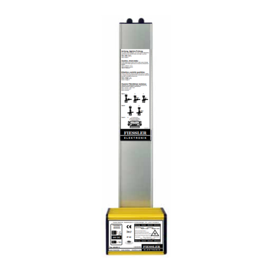
Achtung, tägliche Prüfung:
Vor jedem Schichtbeginn und nach jedem Werkzeug-
wechsel ist die Lichtschranke wie folgt zu prüfen:
Test 1: Bild 1 bis 3
Test 2: Bild 4 und 5
Test 3: Bild 6
Caution, check daily:
At the beginning of each shift or after every change
of tools the safety light barrier should be checked as
follows:
Test 1: Picture 1 to 3
Test 2:Picture 4 and 5
Test 3: Picture 6
Attention, contrôle quotidien:
Avant le début de chaque équipe de travail ou après
ou chaque changement d'outil, la barrière de sécurité
doit être contrôlée comme suit:
Test 1: image 1 - 3
Test 2: image 4 et 5
Test 6: image 6
Huomio! Päivittäinen tarkistus:
Valoverho on tarkistettava jokaisen työvuoron tai
työkalunvaihdon jälkeen seuraavasti:
Koe 1: kuvat 1: stä 3: een
Koe 2: kuvat 4 ja 5
Koe 3: kuvat 6
Test 1:
1.
2.
3.
Stop
Test 2:
4.
5.
Stop
Test 3:
6.
LS unterbrochen
light curtain interrupted
Barreira laser interrompida
valoverho häiritty
Test
DokuNr.878
FIESSLER
E L E K T R O N I K
Fiessler Elektronik - Kastellstrasse 9 - D 73734 Esslingen - Tel.: ++49-711-919 697-0
Steckerbelegung
Warnung
Caution
Attention Attenzione
Connections
Connecteurs
Laserstrahlung
Laserbeam
Allaccamento
Rayon Laser
Raggio Laser
Nicht in den Strahl blicken !
Typ 4
PE =
Do not look direktly into the beams
S - = 0V
EN 61496
S + = +24V
Nes pas mettre les yeux dans les rayons!
(+10%)
Non Puntare Direttamerte Negli Occhi!
24V DC
IP 40
Laserklasse 1
Class 1 Laser product
Laser classe 1
max. < 1mW / 670 nm + 15 nm
Warnung
Caution
Attention Attenzione
1 = +Motor
2 = - Motor
DOK 850
FIESSLER
Typ: AKAS® 3
Lasersender
E L E K T R O N I K
Laser-Transmitter
Laser-émetteur
Emettitore Laser
Press Brake Protection System safety category 4
AKAS®-3PM, AKAS®-3PF
Operating Instructions
Adjustment
R X O K2
E 2
P 1
R X O K1
N LW
Ka ste nbie ge n
E 4
P 2
N A1
box-bending
Muting
N A3
E 6
N A2
Typ 4
F U S
Ausricht-
kontrolle n
E N 6 1 4 9 6
F U O
E D M O
FIESSLER
O S S D 1
off
E D M S
O S S D 2
S P
E L E K T R O N I K
S G A
Typ: AKAS®-3PF
O S S D 1
on
S G O
O S S D 2
S G S
Empfänger / Receiver
CONTENTS:
Safety Instructions
Application
Instruction for use
Mechanical data
Electrical connection
Putting into operation
SI
Safety Instruction
Read and understand this section prior to
installing and operating the system AKAS®
Please observe always!!!
Telefon: 0711 / 91 96 97-0
Telefax: 0711 / 91 96 97-50 eMail: info@fiessler.de
USA Version
translation
See page S1/ 52
Internet: http://www.fiessler.de
Advertisement
Table of Contents

Summary of Contents for Fiessler AKAS-3PM
- Page 1 Barreira laser interrompida valoverho häiritty Test DokuNr.878 FIESSLER E L E K T R O N I K Fiessler Elektronik - Kastellstrasse 9 - D 73734 Esslingen - Tel.: ++49-711-919 697-0 Adjustment R X O K2 Steckerbelegung R X O K1 Warnung...
-
Page 2: Table Of Contents
How to proceed during the mounting of the AKAS® -system 1a. Overrun Traverse Measuring / 1b. Dip Switch Adjustiment 2. Design of a Mechanical Suspension Device - void if Fiessler holders are used 3. Mounting of the suspension devices at the ram 4. -
Page 3: Indicator Lights On Frontpanel And Switches For Safe Operation
Indicator lights on Frontpanel and switches for safe operation FIESSLER E L E K T R O N I K AKAS®-3PF Indicator lights for in- and out- puts (see page 38) RXOK2 Outputs for RXOK1 release of rear stoppers Adjustment... - Page 4 Indicator lights on Frontpanel and switche for safe operation FIESSLER E L E K T R O N I K AKAS®-3M Ausricht- Indicator lights kontrolle n Typ: AKAS®-3PM in- and outputs (see page 38) Empfänger / Receiver Ka ste nbiege n...
- Page 5 Safety instructions FIESSLER E L E K T R O N I K please notice absolutely This is the operating instruction for the AKAS® models: AKAS®-3PM, AKAS®-3PF. Special instructions for each model are provided with its individual model marking. Attention is drawn to all safety instructions by this symbol.
- Page 6 AKAS®-3PF and a cam controller or by the Fiessler AMS-system . Before the initial start-up, the overrun traverse must be checked either by using the test rod (see page 9) or by using an Overrun Traverse measuring device. (upon customer's request, Fiessler Elektro- nik will perform the Overrun Traverse Measuring on the customer's machine.) If one results of 10 consecutive measure-...
-
Page 7: Prerequisites For Using The Press Brake Protection Akas
ESPE. Upon customer's request, Fiessler Elektronik will perform the initial acceptance as well as the annual test. Additionally, customer training seminars on how to execute annual tests will be conducted at regular intervals. -
Page 8: Description And Fields Of Application For The Equipment
Description and fields of application for the equipment FIESSLER E L E K T R O N I K General Instructions The laser - accident preventing light barrier AKAS® is an electro sensitive protective and controlling device (ESPE) which has the function to protect operators from accidents. -
Page 9: Function Description / Characteristics
Description and fields of application for the equipment FIESSLER E L E K T R O N I K Function Description / Characteristics systems without operating mode se- systems with operating mode selec- lection tion operation only with additional safety with integrated safety fuunctions PLC (e.g. - Page 10 Description and fields of application for the equipment FIESSLER E L E K T R O N I K Function description during bending of flat sheet metal bending of flat sheet metal The V opening of the die must be covered with the lateral die cover. This is necessary because the receiver element E2 must be interrupted before the SP signal ( blanking signal ) is activated.
-
Page 11: Function Description During Bending Of Flat Sheet Metal / Bending Of Wavy Sheet Metal
Description and fields of application for the equipment FIESSLER E L E K T R O N I K Function description during bending of flat sheet metal Advice The beams of the AKAS® must be located at a certain distance to the bending punch. - Page 12 Description and fields of application for the equipment FIESSLER E L E K T R O N I K Function description during bending of boxes Function principle 1. "Box Bending" is activated by the box bending button. The signal at the box bending input KAST must be high box bending (+24V) for at least 100 ms and after that low (0V) for at least 100 ms.
-
Page 13: Mechanical Data, Dimension Drawings
The aluminium housing of both transmitter and receiver are powder coated in RAL 1020 yellow. The optical he- ad is made of acid-resistant spherically reinforced plastic (polyamide). The support housings are of eloxal coated aluminium. fastening With Fiessler tenon blocks dimensions fastening screws M 6 x 30... -
Page 14: Max. Standard-Range,Max. Positioning Range Of The Supports, Fiessler Holders
Mechanical data, dimension drawings FIESSLER Max. Standard-Range / Max. positioning range of the supports / Fiessler Holders E L E K T R O N I K max. Standard-Range between transmitter/receiver unit max. Upper tool length max. Upper tool length 6m... -
Page 15: Mounting
Measurement the AKAS®-...F and a cam controller or by the Fiessler AMS-system . Before the initial start-up, the overrun tra- verse must be checked either by using the test rod (see page 9) or by using an Overrun Traverse measuring device. - Page 16 E L E K T R O N I K 2. design of the holders - The dimensions of the self-supplied holders must be individually laid out according to the dimensions void if Fiessler holding Devices of the press brake. are used - The self-supplied holders must be made of torsion-free rigid material, e.g.
- Page 17 AKAS®-3... Remove the fastening plate from the Fiessler holder Fiessler holder and tighly fasten it by 2 M5 s liding tenon blocks are loca- using the tenon blocks at the AKAS®. ted in each groove for fastening...
- Page 18 Mounting FIESSLER E L E K T R O N I K Adjustment of the AKAS® at the first installation -AKAS®-3... 6. Adjustment of the AKAS® both supports must be mounted in a way that: at the first installation 1. the highest (biggest) bending punch and the smallest bending puch is within the range of the supports.
- Page 19 Mounting FIESSLER E L E K T R O N I K adjustment of the AKAS® at the first installation -AKAS®-3... fine adjustment The support of the transmitter must be turned around both the longitudinal and vertical axis until the laser beams are aligned parallel to the ram.
- Page 20 Mounting FIESSLER E L E K T R O N I K Adjustment of the AKAS® at the first installation correction of adjustment errors Dejustage possibility Remedy AKAS®-3P... AKAS®-3P... Position of dark (=covered) section is By unscrewing all M6 adjustment...
- Page 21 Mounting FIESSLER E L E K T R O N I K adjustment of the AKAS® at the first installation AKAS®-3... adjustment control synchronization transmitter - receiver AKAS®-3... Adjustment - LEDs transmitter-beam does focus at all E...on P...off transmitter-beam does not E...partially off...
- Page 22 Mounting FIESSLER E L E K T R O N I K adjustment directions - after tool change AKAS®-3P... 1.For the first adjustment or after a tool change the key operated switch at adjustment directions Empfänger auf Sender auf aus off...
- Page 23 Mounting FIESSLER E L E K T R O N I K 5.9,5.10 Automatic overrun traverse test AKAS®-3PF 8. Verification of all electrical see chapter 6 Electrical connections connections referring to safety class 4 9. Automatic overrun traverse According to prEN 12622, the overrun traverse of the machine must be verified automatically at the first stroke test after its connection to power of the press brake or of the AKAS®...
-
Page 24: Electrical Data
Any modification of the specified circuits can cause hazardous states and is therefore forbidden. If the press does not posssess any position-monitored contactors for the switch-over from fast speed into slow speed, a safe integration is possible using the Fiessler AMS-System. Doku Nr. 1379 Stand 27.1.2017 /Aui... - Page 25 Electrical connections - Description / Wiring diagrams FIESSLER Directions for the integration into the machine control system E L E K T R O N I K Muting signal Muting signal from the machine control system: (Mutingsignal available from the contactor position control of the working stroke valve, from the pressure switch or from the AMS) The muting signal out of the machine control must be laid out in a way that no muting signal is given to AKAS®...
-
Page 26: Akas®-3Pm (Operation Only With Additional Safety Plc)
Electrical connections - Description / Wiring diagrams FIESSLER E L E K T R O N I K -operation only with additional safety PLC AKAS®-3PM FPSC) (e.g.FPSC) function - protection of the operator from being squeezed between the ram and the matrix (all other safety monitoring functions are carried out by a safety control (e.g. - Page 27 Electrical connections - Description / Wiring diagrams FIESSLER -operation only with additional safety PLC (e.g.FPSC) AKAS®-3PM E L E K T R O N I K AKAS®-3PF -with HEX switch position 00 00 AKAS®transmitter AKAS® Sender functional ground Erde safety control,...
- Page 28 Electrical connections - Description / Wiring diagrams FIESSLER E L E K T R O N I K AKAS®-3PF -with selectable safety functions functions AKAS®-3PF provide - apart from the standard functions - more safety functions which enable the moritoring and control of a press brake without additional safety PLC.
- Page 29 Electrical connections - Description / Wiring diagrams FIESSLER AKAS®-3PF -with selectable safety functions E L E K T R O N I K example for operation mode example for operation mode Terminals of the Receiver AKAS®-3F / -IIF B8 B8 or F8 F8...
-
Page 30: Akas
Electrical connections - Description / Wiring diagrams FIESSLER -with selectable safety functions AKAS®-3PF E L E K T R O N I K Machine-Safety monitoring by AKAS®-3PF wiring diagram 2/ p. 30 Doku Nr. 1379 Stand 27.1.2017 /Aui... -
Page 31: Monitoring Of The Foot Pedal
Electrical connections - Description / Wiring diagrams FIESSLER 6.4.1 E L E K T R O N I K AKAS®-3PF -with selectable safety functions 1. operation with additional FPSC) The safety PLC (e.g. is responsible for the fast speed / slow speed position control and provides ®... -
Page 32: Monitoring Of The Door- And The Emergency Off-Circuits, Emergency-Off Of The Motor-Driven Rear Stoppers
Electrical connections - Description / Wiring diagrams FIESSLER 6.4.1 AKAS®-3PF -with selectable safety functions E L E K T R O N I K 5. Control of the stop AKAS® monitors in a safe way both positions of the stop- and the fast speed closing state of the contac-... - Page 33 Instead of using a rear protective metal grid, a safety light grid with equivalent switching outputs, e.g. with lightgrid type Fiessler ULVT / TLVT or ULCT / TLCT as shown in wiring diagram 6/p.33 is possible. with equivalent switching outputs...
- Page 34 Electrical connections - Description / Wiring diagrams FIESSLER 6.4.1 AKAS®-3PF -with integrated safety functions E L E K T R O N I K 7. Installation operating mo- A selector switch provides the possibility to choose between operating mode with activated protective de, i.e.
- Page 35 +24 V signal is given to KAST. This signal is provided by a traverse measuring system (e.g. Fiessler AMS, or NC) which indicates that the traverse has been actually covered. By this, the upper receiver element remain activated as long as possible even in the case of a very low slow speed, and intermediate stops during slow speed.
- Page 36 Electrical connections - Description / Wiring diagrams FIESSLER 6.4.2 E L E K T R O N I K Programming of the integrated safety functions via Hex-switches AKAS®-3PF By the use of 4 Hex switches different operating modes can be selected.
- Page 37 Electrical connections - Description / Wiring diagrams FIESSLER 6.4.2 E L E K T R O N I K Programming of the integrated safety functions via Hex-switches AKAS®-3PF The Hex-switches must always be programmed in pairs (1 and 3, 2 and 4). Within each pair, equal values must be programmed.
-
Page 38: Displaying Outputs, Indicator Leds
Electrical connections - Description / Wiring diagrams FIESSLER E L E K T R O N I K Displaying outputs / indicator-LEDs Displaying of conditions lamp is out (flashing is hardly recognizable) : during the closing movement the protective field is at least par-... - Page 39 Before the SP input is activated the receiver element E2 re- only AKAS...P SP too early spectively E4 must be interrupted by the Fiessler magnet pla- te. Set the SP output of your machine to a corresponding value. Stop at the overrun traver-...
- Page 40 Internal error if this is displayed again after the voltage reset, a verification background grey: protective circuit by Fiessler Elektronik is necessary other message or error within the protective cir- open again all protective grids and Emergency off buttons no message, if mo-...
- Page 41 Hex switches deadjusted Readjust the Hex switches onto the selected opera- ting mode, then carry out a voltage reset. If the error repeats itself, a repair by Fiessler Elektronik is ne- cessary. invalid Hex switch position Turn HEX switch into a permitted position...
-
Page 42: Service / Maintenance / Warranty
Returning a unit If, in the case of default, the necessity of returning the unit to Fiessler Elektronik arises, it will be very advantageous for a fast default diagnosis if the following topics are observed and observed:... - Page 43 I/O signals depending on time, moving distance and movementspeed FIESSLER E L E K T R O N I K AKAS3P M/F Normal stroke from TDC >11mm above clamping point with max. machine overrun of 5mm Speed 0 s min.27ms max.800ms...
- Page 44 I/O signals depending on time, moving distance and movementspeed FIESSLER E L E K T R O N I K AKAS3P M/F Normal stroke from 11mm >=TDC > 8mm above clamping point with max. machine overrun of 5mm. Speed 10mm/s Stroke <11mm...
- Page 45 I/O signals depending on time, moving distance and movementspeed FIESSLER E L E K T R O N I K AKAS3P M/F Normal stroke from TDC >= 8mm above clamping point with max. machine overrun of 5mm Speed 10mm/s Stroke...
- Page 46 I/O signals depending on time, moving distance and movementspeed FIESSLER E L E K T R O N I K AKAS3P M/F Stroke with initial interrupted protection field from 11mm >=TDC > 8mm above clamping point with max. machine overrun of 5mm...
- Page 47 I/O signals depending on time, moving distance and movementspeed Signale in Abhängigkeit von Zeit, Weg, Geschwindigkeit FIESSLER E L E K T R O N I K AKAS3P M/F (same as for AKAS3 M/F) Box bend stroke from TDC >12mm above clamping point with max. machine overrun of Speed 0 s min.500ms...
-
Page 48: Order Codes
Order codes assessories FIESSLER E L E K T R O N I K AKAS® accessories (electronic equipment) part designation order code AKAS® Muting System w. integrated overrun traverse control AMS/N, complete (incl. 2 magnetic sensors with 10m & 5m cables,... - Page 49 AKAS®-Checking protocoll Inspection Sheet Inspection of a press brake safeguarded by a press No.: brake protection system AKAS® Date: Hex switch position:_____________________________ customer‘s order number: machine builder company: Serial no.. machine type: address: machine control by: department: machine located at: Post Code/City: inventory no.: cost centre:...
-
Page 50: Declaration Of Conformity
Declaration of conformity FIESSLER E L E K T R O N I K FIESSLER E L E K T R O N I K Fiessler Elektronik GmbH & Co. KG Kastellstr. 9 D -73734 Essling e n Managing directors Modèle recommandé... -
Page 51: Terms
The electrosensitive protective device (ESPE) switches automatically into the "safe state" when it is faulty. Standard Installation range Maximum distance between transmitter and receiver is 8 m. (For longer range please get in contact with Fiessler Elektronik or your local dealer). Max. Upper tool length The maximum upper tool length is 6m. - Page 52 Safety Instructions FIESSLER WARNING! Read and understand this section prior to installing and operating E L E K T R O N I K the system AKAS ® Please observe always Attention is drawn to all safety instructions by this warning-symbol. Particular attention must be paid to such in- structions.
- Page 53 Safety Instructions FIESSLER WARNING! Read and understand this section prior to installing and operating E L E K T R O N I K the system AKAS ® Please observe always WARNING: The Check Daily Procedure must be also performed after any maintenance, adjustment, modification to the pressbrake safety system AKAS ®...
- Page 54 Safety Instructions FIESSLER WARNING! Read and understand this section prior to installing and operating E L E K T R O N I K the system AKAS ® Please observe always No protection by AKAS ® No protection by AKAS ®...
- Page 55 Safety Instructions FIESSLER WARNING! Read and understand this section prior to installing and operating E L E K T R O N I K the system AKAS ® Please observe always The transmitter generates two or three modulated visible laser light beams.
- Page 56 — Follow all procedures in this manual for proper operation of the pressbrake safety system AKAS ® . The enforcement of these requirements is beyond the control of Fiessler Elektronik. The employer has the sole responsibility to follow the preceding requirements and any other procedures, conditions and requirements specific to his machinery.
- Page 57 Notes FIESSLER E L E K T R O N I K Doku Nr. 1379 Stand 27.1.2017 /Aui...
- Page 58 Safety-Light-Grid with muting function Service As a special feature for training our customers, Fiessler Elektronik offers one-day safety workshops. Our service team provides you with expert advice and information for the reliable integration of our safety equipment into your machine.
Need help?
Do you have a question about the AKAS-3PM and is the answer not in the manual?
Questions and answers