
Summary of Contents for iDig 2D Touch
- Page 1 2D Touch User Manual Bridgin Groupe 21 Boulevard Littré 78600 Le Mesnil le Roi France +33 9 73 87 04 25 www.idig-system.com...
-
Page 2: Table Of Contents
Table of Contents Calibration Procedures Applications Troubleshooting Pre-start Checklist #1 Main Screen Operation Pre-start Checklist #2 Digging to an Elevation Calibration Hardware Installation Digging a 15 ft wide excavation using the Reach Other Installation Procedures – Main Boom Sensor Function Installation Procedures –... -
Page 3: Calibration Procedures
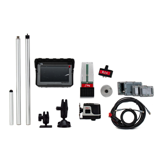
Calibration Procedures Bridgin Groupe 21 Boulevard Littré 78600 Le Mesnil le Roi France +33 9 73 87 04 25 www.idig-system.com... - Page 4 Pre-Installation Checklists Before you begin to install the iDig, make sure you’ve got everything you need to successfully complete the installation along with checking your equipment and your working area. Prestart Checklist #1 – Items to have on hand to assist with installation ✓...
- Page 5 Pre-Installation Checklists Before you begin to install the iDig, make sure you’ve got everything you need to successfully complete the installation along with checking your equipment and your working area. Prestart Checklist #2 – Machine Checks Have you got a SAFE and SUITABLE location for the install? This calibration process requires a bit of space to operate the machine in.
-
Page 6: Hardware Installation C
Hardware Installation Step 1 – Installation of LED Display and Control Box Machine needs to be powered OFF • Before plugging in the cables, find suitable locations to mount the LED Cradle and Control Box Cradle • The LED Display should be put on the front window so that is in your field of vision of the working area outside. - Page 7 Hardware Installation Step 2 – Installation of 2D Sensor Locating a suitable spot to install the 2D Sensor is worthwhile taking some time to get right. You are looking for a place that: • Is accessible – the Sensor is able to be reached and removed from its mounting plate with the removal key without interference.
- Page 8 Hardware Installation Step 2 – Installation of 2D Sensor (Cont.) Examples of 2D Sensor installation: Set-up for Backhoe only...
-
Page 9: Installation Procedures - Main Boom Sensor
Installation Procedures – Main Boom Sensor Boom Sensor • Find a suitable location on the boom that is near the cab to install the Boom Sensor. You are looking for a spot that is easy to access when installing or removing the sensor day to day. On smaller machines this is commonly in the lower 1/3 of the boom on the left hand side of the machine. -
Page 10: Installation Procedures
Installation Procedures – 2 Boom Sensor Boom Sensor • Find a suitable location on the 2 boom, left or right side, to install the 2nd Boom Sensor. You are looking for a spot that is easy to access when installing or removing the sensor day to day. •... -
Page 11: Installation Procedures - Dipper Stick Sensor E
Installation Procedures – Dipper Stick (Combo) Sensor Dipper Stick (Combo) Sensor • The Combo Sensor will need to be located on the dipper as low as possible. The higher the Sensor is located the more the boom and dipper has to be dropped to catch the laser beam. - Page 12 Take a measurement from the center of the top pin (C) to the center of the Combo Sensor (B) staying on the string line. This will be the A-C measurement. The A-B measurement will be 0. Enter these measurements via the System Settings menu once the main iDig calibration steps have been completed.
-
Page 13: Installation Procedures - Bucket Sensor
Installation Procedures – Bucket Sensor Installing Bucket Sensor • The Bucket Sensor can be installed on either side of the machine and on either the dog-bone or the quick connect. • “Inside” the quick connect or dog-bone is acceptable as well. Watch the sensor side if prompted by the system. The correct sensor side is the direction that the plastic cap of the sensor is facing. -
Page 14: Installation Procedures - Initial Settings G
Installation Procedures – Initial Settings • • Select the desired Slope Units and Length Basic settings are required when performing the initial calibration. Select a Units and press “Apply”. language and press “Apply”. Initial settings are complete. Go to “System Settings”. -
Page 15: Installation Procedures - System Settings
Installation Procedures – System Settings • • Select machine type Select the type of coupler being used • • Select the tool to be used. CAREFUL - Tilt Select No Pitch/Chassis and press “Apply”. The 2D Sensor will be calibrated coupler or tilt bucket should only be selected if there is a tilt bucket kit to be last. - Page 16 • You will also need a tripod, preferably an elevating tripod. From your iDig kit you will need: Laser Pointer (XB525), Tripod Mount (XD477), Magnetic Pivot Target (XD470, Laser Pointer Adaptor (XD478) and the Extension Poles (XD471).
- Page 17 Installation Procedures – Main Boom & Dipper Stick Calibration The system will now automatically detect which side of the elements the Sensors have been installed on: Dipper Combo Sensor • • Raise the boom and dipper stick, press Lower the dipper stick ONLY until the pop- “Next”...
- Page 18 Installation Procedures – Main Boom & Dipper Stick Calibration The system will now automatically detect which side of the elements the Sensors have been installed on: Main Boom Sensor • • Raise the boom and dipper stick again, Lower the main boom ONLY until the pop- press “Next”...
- Page 19 Installation Procedures – Main Boom & Dipper Stick Calibration The system will now automatically detect which side of the elements the Sensors have been installed on: Boom Sensor (if applicable) • • Raise the boom and dipper stick again, Lower the main boom ONLY until the pop- press “Next”...
- Page 20 Installation Procedures – Main Boom & Dipper Stick Calibration • If possible, remove the bucket before starting this procedure. Re-attach the bucket when completed. • Once the Sensor sides have been determined, you will now begin the main boom and dipper stick calibration. •...
- Page 21 Installation Procedures – Main Boom & Dipper Stick Calibration • Raise the Laser Pointer to a new, higher elevation using the extension tubes provided. Do move the tripod while unscrewing and replacing the laser pointer on the tubes! • Move the main boom and dipper stick through a series of movements placing the laser beam onto the tube each time. •...
- Page 22 Installation Procedures – Main Boom & Dipper Stick Calibration Calibration Results of Booms • This screen shows the boom’s lengths that were created during the calibration process. • You can give your machine a unique name by pressing “Rename”. • If you feel the calculated lengths are incorrect, measure the length of the extension tubes.
- Page 23 Installation Procedures – Bucket Calibration Calibrating the Bucket • There are two methods of calibrating the Bucket: Manual and Automatic. The manual process is much quicker and more accurate. • The automatic process is similar in concept to the Excavator setup whereby you will move the bucket through a series of incremental angle changes while keeping the bucket tip/edge on a fixed point.
- Page 24 Installation Procedures – Bucket Calibration Manual Bucket Calibration • Place a magnetic plumb-bob on the bucket pivot pin. • Drop the string line below the edge of the bucket tip/edge. Make sure the string is still. • Slowly close the bucket until the tip/edge of the bucket is just touching the string. The center of the bucket pivot pin should be plumb to the tip/edge of the bucket.
- Page 25 Installation Procedures – Bucket Calibration Manual Bucket Calibration • • The bucket will be named in your system as New Press “Vertical” so that it is highlighted in blue. Select which side the Bucket Sensor has been installed so that Bucket.
- Page 26 Installation Procedures – Bucket Calibration Manual Bucket Calibration • To change the bucket name and to activate the Floating position of the bucket: • Press the Gearbox icon on the main screen. • System Settings > • Select or Edit Machine > •...
- Page 27 Installation Procedures – Bucket Calibration Manual Bucket Calibration • • Make sure your bucket is flat on the Press the green check mark on the screen. • Press “Apply”. Your bucket calibration is ground like the illustration below and then now complete! press “Offset Wizard”.
- Page 28 Installation Procedures – Bucket Calibration Automatic Bucket Calibration - Dog Bone • You will require a stable point on which to place the tip/edge of the bucket. • This point needs to be high enough so that you can open and close the bucket as much as possible. •...
- Page 29 Installation Procedures – Bucket Calibration Automatic Bucket Calibration - Dog Bone • • • Slowly close the bucket until the pop-up Once the Sensor is in position press The system needs to detect which side of “Next” screen appears. If the correct side is the bucket the Sensor is installed.
- Page 30 Installation Procedures – Bucket Calibration Automatic Bucket Calibration - Dog Bone The automatic calibration of the bucket requires the bucket to be placed on the EXACT same point while incrementally changing the angle of the bucket. There are ten steps to this process. Note the counter on the bottom right hand side of the screen.
- Page 31 Installation Procedures – Bucket Calibration Automatic Bucket Calibration - Dog Bone • • • Place the bucket on the ground in a flat Your automatic bucket calibration is Enter the bucket width and Press “Next” floating position. Press “Next”. This will complete! Press “Done”...
- Page 32 Installation Procedures – Laser Receiver Calibration Laser Receiver Calibration - Manual Take the laser receiver measurements discussed earlier in this section and enter them in the machine parameters: • Press the Gearbox button on the Main Screen then: • System Settings > •...
- Page 33 • Turn on the Laser. • The iDig Combo Sensor needs to receive the laser beam while moving through an arc with the dipper stick in close to the cab and then the dipper stick extended away from the cab.
- Page 34 Installation Procedures – Laser Receiver Calibration Laser Receiver Calibration - Automatic • • Place the laser receiver at the center of the • Read the reminder on the screen and press Bring the dipper stick as close to the bucket pivot pin and raise the boom and “OK”...
- Page 35 Installation Procedures – Laser Receiver Calibration Laser Receiver Calibration - Automatic • • • The final screen for your Laser Receiver Without moving the main boom, extend If you should move the main boom calibration shows the calculated the dipper stick away from the machine between steps 2 and 3, the 2 angle until you get an on-grade signal from the...
- Page 36 Installation Procedures – 2D Sensor Calibration The 2D Sensor is sensitive to vibration and it’s recommended that you have the machine operating at medium to high RPM during the following alignment process. Higher RPM reduces the vibration and leads to a more accurate calibration.
- Page 37 Installation Procedures – 2D Sensor Calibration • • Align the machine forward and parallel to Wait for the system to complete the the tracks. Press “Next”. alignment process before moving. • • Rotate the cab 90° so that the cab is Rotate the cab 90°...
- Page 38 Installation Procedures – 2D Sensor Calibration • • Press “Done”. Your 2D sensor calibration is Rotate the cab 90° so that the cab is complete! perpendicular to the tracks. Ignore the angle bubble vial, Press “Next”.
- Page 39 Installation Procedures – Tilt Bucket Calibration Install the Sensors • Install the Triangle Holder on the lower part of the tilt axis as shown on these pictures: On a tilt bucket On a quick link tilt device On a compact quick link tilt device •...
- Page 40 Installation Procedures – Tilt Bucket Calibration Install the Sensors • If there is no space available to setup the Triangle Holder, it is possible to install the 2 Mini Sensors without it. It is mandatory to proceed by the following 4 rules: •...
- Page 41 Installation Procedures – Tilt Bucket Calibration Install the Sensors • If there is no space available to setup the Triangle Holder, it is possible to install the 2 Mini Sensors without it. It is mandatory to proceed by the following 4 rules: •...
- Page 42 Installation Procedures – Tilt Bucket Calibration Install the Sensors • If there is no space available to setup the Triangle Holder, it is possible to install the 2 Mini Sensors without it. It is mandatory to proceed by the following 4 rules: •...
- Page 43 Installation Procedures – Tilt Bucket Calibration Install the Sensors • If there is no space available to setup the Triangle Holder, it is possible to install the 2 Mini Sensors without it. It is mandatory to proceed by the following 4 rules: •...
- Page 44 Installation Procedures – Tilt Bucket Calibration Install the Sensors • Some examples of a Triangle Holder free setup:...
- Page 45 Installation Procedures – Tilt Bucket Calibration Calibration on a New Machine • Perform a complete machine calibration: • Select machine type...
- Page 46 Installation Procedures – Tilt Bucket Calibration Calibration on a New Machine • Select the machine’s configuration Tilt Bucket with Standard Coupler Quick Link Tilt Coupler...
- Page 47 Installation Procedures – Tilt Bucket Calibration Calibration on a New Machine • Continue by following the instructions on the screen: • • • Make sure you have the Tilt A & Tilt B Slowly close the bucket between a range of Close the bucket to horizontally level the Sensors paired to the system and placed 35°-55°.
- Page 48 Installation Procedures – Tilt Bucket Calibration Calibration on a New Machine • Continue by following the instructions on the screen: • • The calibration of the tilt bucket is done! Verify/enter the bucket width. Make sure you are using • Click on “Done”.
- Page 49 Installation Procedures – Tilt Bucket Calibration Calibration on an Existing Machine • To add support for tilt on an already calibrated machine, select an already calibrated bucket and go into “System Settings”: • Select “Calibrate Tilt of Bucket” if the actually attached and selected bucket has it’s own tilt mechanism.
- Page 50 Installation Procedures – Tilt Bucket Calibration Machine Parameters • No tilt available • • On the “Buckets” tab the “Tilt” option is unchecked. On the “QuickLink” tab the “Tiltable Quicklink” option is unchecked. NOTE – The Tilt Calibration is not available in Manual Mode. See previous instructions to launch a Tilt Bucket Calibration.
- Page 51 Installation Procedures – Tilt Bucket Calibration Machine Parameters • Tilt on bucket(s) • • On the “Buckets” tab the “Tilt” option is checked. On the “QuickLink” tab the “Tiltable Quicklink” option is unchecked. NOTE – To redo the calibration of this bucket, remove the corresponding tilt calibration by un-checking the “Tilt” box. Then you can re- run a Tilt Calibration.
- Page 52 Installation Procedures – Tilt Bucket Calibration Machine Parameters • Quick link tilt • • On the “Buckets” tab the “Tilt” option is checked. On the “QuickLink” tab the “Tiltable Quicklink” option is checked. NOTE – By un-checking the “Tiltable Quicklink” box option you’ll remove the tilt calibration for all buckets.
- Page 53 Installation Procedures – Auger Calibration Requirements • iDig Tilt Bucket Kit. • You must have an Auger with one of the following configurations:...
- Page 54 Installation Procedures – Auger Calibration Install the Sensors • Install the Triangle Holder on the tilting, but not rotating part of the auger as shown in this picture. • The Triangle Holder may be setup in position or orientation. • If there is no space available for the Triangle Holder, it is possible to install the 2 Mini Sensors without it.
- Page 55 Installation Procedures – Auger Calibration Calibration on a New Machine • Perform a complete machine calibration: • Select machine type...
- Page 56 Installation Procedures – Auger Calibration Calibration on a New Machine • Select the machine’s configuration • This function is not compatible with a Tiltable Quick Coupler.
- Page 57 Installation Procedures – Auger Calibration Calibration on a New Machine • • • Put the Auger exactly vertical. Bucket Sensor detection Orientation of the Tilt Kit • • • Use the bucket open/close control to place Use the bucket close control to pull back While holding the auger inclined with the tip towards the cab approximately 35°...
- Page 58 Installation Procedures – Auger Calibration Calibration on a New Machine • • “T” height of the auger Length of the auger • • Measure and enter the T height of the auger using the Measure and enter the length of the auger from the front/rear and left/right hinge.
- Page 59 Installation Procedures – Auger Calibration Calibration on a New Machine • Quick coupler • • Align the swing pivot/quick ling and the front/rear Measure and enter the distance between the swing pivot on a vertical axis. pivot/quick link and the front/rear pivot of the auger. •...
- Page 60 Installation Procedures – Auger Calibration Calibration on a New Machine • • The calibration of your auger is done! One of the Main working screens of the Auger • Click on “Done”. Function.
- Page 61 Installation Procedures – Auger Calibration To Add a New Auger to an Already Calibrated Machine • • The parameters of the auger are accessible from the From the “System Settings” menu click on “Calibrate “Buckets” tab of the “Machine Parameters” menu. Bucket”...
- Page 62 Installation Procedures – Engcon Rotative Coupler Calibration iDig Compatibility • The iDig System and the Engcon rotative coupler may be connected via a CAN Communication. To be sure that your iDig system is compatible with the CAN communication, you need to check 2 important points: The CAN communication is compatible with the C8 iDig Control Box only.
- Page 63 Installation Procedures – Engcon Rotative Coupler Calibration iDig Compatibility • The iDig System and the Engcon rotative coupler may be connected via a CAN Communication. To be sure that your iDig system is compatible with the CAN communication, you need to check 2 important points: The CAN communication is compatible with the CAN capable iDig Control Box Cradle only.
- Page 64 Installation Procedures – Engcon Rotative Coupler Calibration Engcon Tilt Rotator Coupler & Engcon C2C Control System Attention! Please refer to the Engcon documentation! • • Connect to the iDig CBox Cradle Connect to the Engcon Coupler...
- Page 65 Installation Procedures – Engcon Rotative Coupler Calibration Setup Rotative Coupler • • To access this function there needs to be a Select the predefined Engcon coupler from CAN cable connected to the Control Box the drop down menu. • Cradle, otherwise the button will be If the coupler is not listed in the drop grayed out and unusable.
-
Page 66: Tilt Bucket Calibration Procedures
Installation Procedures – Engcon Rotative Coupler Calibration Setup Rotative Coupler • Set the bucket rotation to zero and the rotative coupler axis vertical. • Click on “Next”. • The rotative coupler calibration is done, but not the tilt calibration! • Refer to the “Tilt Bucket Calibration Procedures”... - Page 67 Installation Procedures – Dozer Calibration • The Grade-to-Blade feature REQUIRES that your machine have the Big Combo Sensor installed and paired with the Standard Combo Sensor system instead of the standard Combo Sensor. • There must also be a Mini Sensor installed and paired with the system on one of the dozer blade arms.
- Page 68 Big Combo Replacement • Do not remove the Standard Combo Sensor yet. • Start your excavator and the iDig system. • Touch anywhere on the Main Screen to have the icons fly in from the side. Click on the Sensor Symbol.
- Page 69 Installation Procedures – Dozer Calibration Big Combo Replacement • Go to Machine Parameters Take care to select the right machine! • Select the side that the Big Combo is to be installed • Click on the “Offset” value...
- Page 70 Installation Procedures – Dozer Calibration Big Combo Replacement • Click on “Offset Wizard”. • Remove the old Combo Sensor. • Install the new Big Combo Sensor plate but do not attach the sensor yet. • The Sensor Symbol appears missing (red circle). Long press the symbol and install the Big Combo Sensor in order to pair it to the system.
- Page 71 Installation Procedures – Dozer Calibration • • Enter “System Settings” and then select “Dozer with Click on “Calibrate”. • Laser”. Note – If this menu does not appear, ensure that the Big Combo Sensor is detected by the radio.
- Page 72 Installation Procedures – Dozer Calibration • Select your machine from the drop down menu. If your machine is not listed then you will need to make the following measurements: • AB - Forward Shift distance between main boom/chassis pivot point and center of rotation of the machine.
- Page 73 Installation Procedures – Dozer Calibration • • Select which side of the dozer blade arm the Sensor has The calibration of your dozer blade is complete! Click been installed. Relevant to the direction that the on “Done”. plastic cover of the Sensor is facing. •...
- Page 74 Installation Procedures – Dozer Calibration Dozer Fine Tuning After having thoroughly validated each calibration procedure (booms, then bucket, then 2D and then laser in many positions), a depth difference may persist between the teeth of the bucket and the dozer blade relative to the ground. To remove this difference, follow the recommended procedure: •...
- Page 75 Installation Procedures – Mainboom Offset Calibration • • From the “Systems Settings” menu click on “Mainboom Click on “Calibrate”. Parallelogram Offset”.
- Page 76 Installation Procedures – Mainboom Offset Calibration • Select your machine from the drop down menu. If your machine isn’t listed then take the following measurements and input the data: • • • Angle of offset axis • Maximum shift left •...
-
Page 77: Checking The System Accuracy
Checking the System Accuracy Machine & Bucket Calibration Check for Elevation • Place the bucket on a solid spot in front of the machine with the bucket fully open. • Lock the center tooth on the main working screen by taping on the center tooth on the bucket symbol on the left hand side of the screen. •... - Page 78 Checking the System Accuracy Machine & Bucket Calibration Check for Reach • Make sure that the surface on the ground is fairly level from front to back. • Place the bucket on a solid spot far away from the front of the machine with the bucket fully open. •...
- Page 79 Checking the System Accuracy 2D Calibration Check • Setup a rotating laser approximately 5 feet (1.5 m) high with no slope. • Tilt the machine in both axes (forward/back and left/right). • Align the cab parallel to the tracks. • Reach out away from the cab with all of the elements.
- Page 80 Checking the System Accuracy Laser Receiver Calibration Check – Method 1 • Setup a rotating laser approximately 5 feet (1.5 m) high with no slope. • Lock the center tooth on the main working screen by taping on the center tooth on the bucket symbol on the left hand side of the screen. •...
- Page 81 Checking the System Accuracy Laser Receiver Calibration Check – Method 2 • Setup a rotating laser approximately 5 feet (1.5 m) high with no slope. • Lock the center tooth on the main working screen by taping on the center tooth on the bucket symbol on the left hand side of the screen. •...
-
Page 82: Applications
Applications Bridgin Groupe 21 Boulevard Littré 78600 Le Mesnil le Roi France +33 9 73 87 04 25 www.idig-system.com... -
Page 83: Main Screen
Main Screen Change Zoom Zoom Zoom Screen View Default Bucket View Alignment Tape Alignment Measure Countdown Function Sensors in Height Alarm Enable/Disable Laser Height Reach Function Access Vertical Settings Distance Laser Catch Disable First Edit Laser Reference Last Elevation After Moving Slope Setting Edit Elevation Laser Catch... -
Page 84: Digging To An Elevation
Digging to an Elevation Method 1: Using the bottom of the excavation as the reference point... - Page 85 Digging to an Elevation Method 1: Using the bottom of the excavation as the reference point • • • Place the tip of the bucket at the bottom of Enter '0' as the height, you are at the The screen and the LED Display are now the trench and then press the “Elevation”...
- Page 86 Digging to an Elevation Method 2: Using a surveyor’s stake as the reference Surveyor’s Stake 2‘ 6“...
- Page 87 Digging to an Elevation Method 2: Using a surveyor’s stake as the reference • • • Place the tip of the bucket on the Enter a positive value for the desired depth The screen and the LED Display are now surveyor’s stake or hub and then press the to dig to, 2’6”...
- Page 88 Digging a 15 ft wide footing using the Reach function Reference Point 15 ft...
- Page 89 Digging a 15 ft wide footing using the Reach function • • • Align the cab in the direction that you Press the “Reach” button. Touch anywhere on the screen to have the icons fly in from the sides of the screen. want to dig and press the “Alignment”...
- Page 90 Digging a 15 ft wide footing using the Reach function • • • Place the bucket tip/edge on the reference Here a value of 15 ft has been entered and Here a value of -15 ft has been entered spot and enter 15 ft if you want to dig the operator will dig towards the machine.
-
Page 91: Digging To An Elevation Using A Rotating Laser
Digging to an elevation using a rotating laser Method 1: Not knowing the Laser Height Laser Receiver Reference Point 2‘6“... - Page 92 Digging to an elevation using a rotating laser Method 1: Not knowing the Laser Height • • • Click on “Activate the 1 laser catch”. Click on “Bucket Height”. Place the bucket tip/edge on the reference point and enter your positive depth to cut, + 2’6”...
- Page 93 Digging to an elevation using a rotating laser Method 2: Knowing the Laser Height Laser Receiver Laser Height (2’ ¾” + 2’6”) 2’ ¾” 4’6¾” Reference Point 2’6”...
- Page 94 Digging to an elevation using a rotating laser Method 2: Knowing the Laser Height • • • Activate the 1 laser catch. Click on “Set Laser Height”. Enter your laser height, 4’6¾” in this example. • Click on the green check mark to validate. •...
-
Page 95: Changing The Elevation
Changing the Elevation Method 1: Working without a rotating laser Reference Point 2‘3“ 2‘6“ 3“... - Page 96 Changing the Elevation – Working without a rotating laser Method 1 – Changing the elevation by directly changing the digging depth • • • Place the bucket on a known elevation, Enter a new height 3” LOWER than the The bucket is still on the original reference here 2’6”, then click on the “Elevation current height (2’6”...
- Page 97 Changing the Elevation – Working without a rotating laser Method 2 – Changing the elevation by entering an offset • • • Enter the offset, in this case 3”. The digging depth has been RAISED by 3”. Click on the “Offset” button. •...
- Page 98 Changing the Elevation working with a rotating laser 4‘6“ 4‘ 6“...
- Page 99 Changing the Elevation working with a rotating laser Method 1: Directly changing the digging depth • • • Place the bucket on a known height, here Enter a new height that is .20’ LOWER than The digging depth has been raised by .20’ 5.39’, then click on “Elevation Setting”.
- Page 100 Changing the Elevation working with a rotating laser • Method 2: Directly changing the Laser Height • • • Enter a new Laser Height that is .20’ The Bucket Height reference and the Laser Click on “Set Laser Height”. LOWER than the current height (5.62’ > Height decreased by .20’.
- Page 101 Changing the Elevation working with a rotating laser Method 3: Dial in an offset • • Click on the “Move the Reference” button. Click on the “Move Up” or “Move Down” button. • • The Bucket Height and Laser Height have Enter the desired offset, in this case .20’.
-
Page 102: Digging A Trench With 2% Slope
Digging a trench with 2% slope Method 1: Using the bottom of the trench as the reference... - Page 103 Digging a trench with 2% slope Method 1: Using the bottom of the trench as the reference • • • Click on the “Slope” button. Select Single or Dual Slope Choose the direction of the slope you wish to dig. •...
- Page 104 Digging a trench with 2% slope Method 1: Using the bottom of the trench as the reference • • • Place the bucket tip/edge at the bottom of Align the cab to the main slope axis and Enter 0 for your starting elevation. •...
- Page 105 Digging a trench with 2% slope Method 2: Using a surveyor’s stake as the reference point Reference Point 2.50‘...
- Page 106 Digging a trench with 2% slope Method 2: Using a surveyor’s stake as the reference point • • • Choose the direction of the slope you wish Align the cab to the main slope axis and Click on the “Slope” button, then choose Single or Dual Slope.
- Page 107 Digging a trench with 2% slope Method 2: Using a surveyor’s stake as the reference point • Place the tip of the bucket on the reference • • Enter 2.50’ as the height from the bottom The bucket position is now 2.5’ above your point and press the “Elevation”...
-
Page 108: Digging A Trench With 2% Slope Using A Rotating Laser
Digging a trench with 2% slope using a rotating laser Method 1: Not knowing the Laser Height Laser Receiver Note: You must set the same slope in the rotating laser as in the iDig system and align it to the same axis. Reference Point 2.50‘... - Page 109 Digging a trench with 2% slope using a rotating laser Method 1: Not knowing the Laser Height • • • Choose the direction of the slope you wish Align the cab to the slope as previously Click on the “Slope” button. Then choose Single or Dual Slope.
- Page 110 Digging a trench with 2% slope using a rotating laser Method 1: Not knowing the Laser Height • • • The bucket height is shown (2.5’) and the Click on “Bucket Height”. Place the bucket tip/edge on the reference result of the laser catch (2.93’) is shown point and enter 2.5’.
- Page 111 Digging a trench with 2% slope using a rotating laser Method 2: Knowing the Laser Height Note: Laser Receiver You must set the same slope in the rotating laser as in the iDig system and align it to the same axis. Laser Height 2.21’ (2.21’ + 2.50’) 4.71’...
- Page 112 Digging a trench with 2% slope using a rotating laser Method 2: Knowing the Laser Height • • • Choose the direction of the slope you wish Align the cab to the slope as previously Click on the “Slope” button. Then choose Single or Dual Slope.
- Page 113 Digging a trench with 2% slope using a rotating laser Method 2: Knowing the Laser Height • • • The set laser height now shows (4.71’) and Click on “Set Laser Height”. Enter 4.71’ as the Laser Height. • the laser catch shows the needed distance Click on the green check mark and catch to grade (4.46’).
-
Page 114: Using The Dozer Function
Using the Dozer Function • • • Select from three different slope options: Before you can use the dozer function you Tap anywhere on the Main Screen to have level, single slope or dual slope. must first initiate a laser catch. Click on the the system icons fly in from the sides, then •... - Page 115 Using the Dozer Function • • • Enter your value here. Raise/lower your dipper stick to get an on- Choose your referencing method: • • Click on the green check mark. grade signal from your rotating laser. If you know your reference height, place your bucket tip/edge on the reference point and dial it in.
- Page 116 Using the Dozer Function • • • Once the laser catch has been achieved, Align the tracks of the machine in the Turn the cab of the machine so that you this screen will show you the calculated direction in which you intend to grade are in your preferred orientation when you Laser Height.
- Page 117 Using the Dozer Function • • The angle of your cab is now locked. It can be changed This screen indicates the following: • at any time from the main screen. The light bar shows the position of the laser •...
- Page 118 Using the Dozer Function • You are now ready to grade! • As you drive your machine manually adjust the Laser Receiver up or down to make sure you keep the laser signal in the green. • Should you lose your on-grade signal the system will indicate where you lost the signal –...
- Page 119 Moving the Machine – Job site view Job site reference point 60’ trench to dig Existing ground On this job site, a 60’ long trench, 6’ below the reference point which is a sidewalk, has to be built.
- Page 120 Moving the Machine – Set Reference 6’ • Verify that no slope is set (0%) • Put the bucket tip on the reference point • Set your new elevation, press • Enter 6’ and validate...
- Page 121 Moving the Machine – Start digging • Start digging following the indications of the system via the LED Display. • If your machine is not on a level surface, do not move the tracks while you’re digging!
- Page 122 Moving the Machine – Re-reference with the bucket tip • To continue, move the machine forward/backward. • Place the bucket tip on the reference point • Click the « Quick Elevation » button to re-reference the machine:...
- Page 123 Moving the Machine – Re-reference with the bucket tip • Continue digging, using the entire range of the elements to reduce the number of moves with the machine.
- Page 124 Moving the Machine – Re-reference with the bucket tip • With as long as reach possible, touch the bucket on the reference point after the machine has moved. • Click the « Quick Elevation » button to re-reference the machine: •...
- Page 125 Moving the Machine – Reference point out of reach of the bucket tip • Now, you are too far away to reach the reference point. • Without a rotating laser, you may re-bench on the ground on a point that is known to be on grade.
- Page 126 Moving the Machine – Reference point out of reach of the bucket tip 3‘ 6‘ • Setup the rotating laser. • Measure the elevation difference between the laser plane and the reference point. • In this example, the elevation difference to the reference point is 3’, PLUS 6’ elevation difference to the ground, makes a total of 9’.
- Page 127 Moving the Machine – Reference point out of reach of the bucket tip • • Click the «1st Laser Catch» button Click on «Set Laser Height» Note: • If no laser button is visible, then the laser receiver needs to be calibrated. •...
- Page 128 Moving the Machine – Reference point out of reach of the bucket tip • • Enter the Laser Height of 9 feet. Now catch the laser beam and click on • Press the green check mark to validate. “Next”. Note: If the 'AutoCatch' option is enabled you do not need to click “Next”.
- Page 129 Moving the Machine – Reference point out of reach of the bucket tip 9‘ • You can now move the machine and be able to re-reference each time by catching the laser beam. • The Laser Height is already set and defined.
-
Page 130: Changing Buckets
Changing Buckets • • • The bucket that you selected is now the The bucket you are currently using is A drop down menu will show you all of the indicated on the screen. buckets that you have calibrated for that active bucket and is displayed on the •... -
Page 131: Tape Measure Function
Tape Measure function • • • The Tape Measure Mode will give you the When you reach your second point you can Tap the indicated values to zero out the ability to measure the vertical distance, setting and move your bucket to the see the indicated horizonal distance (1.11’), the vertical distance (.44’) and the horizontal distance and percent of slope... -
Page 132: Height Alarm Function
Height Alarm function • • • The Height Alarm function will warn you To activate the Height Alarm, raise one of As you are working, if any of your when any of the machine elements reach a your elements to the maximum elevation machines elements reach the pre-set pre-set height. -
Page 133: Basic Settings
Basic Settings • This Menu gives you access to various settings to change how your iDig system functions. Click on “Basic Settings”. - Page 134 Basic Settings Global Settings • • • Change Slope units and Length units at any Change between languages at any time. Enable or Disable the Audible Alarms as time. well as adjusting the volume. NOTE – If you intend to fine tune or enable/disable specific audible alarms you will have to enter the Work Settings menu to do so.
- Page 135 Sensor Check The Sensors shipped with your iDig have already been paired with the system during production. It is therefore possible to use multiple systems on the same job site without any interference. Each sensor has a label on the back of the sensor indicating which element it is assigned to: •...
- Page 136 Basic Settings – Pairing a New Sensor Method 1: Working from the Main Screen • • • If a sensor is lost or damaged a red sensor This screen shows which sensor is not After the green check mark appears, attach gauge will appear on the screen.
- Page 137 Basic Settings – Pairing a New Sensor Method 2: Working from the Basic Settings menu • • • Click on the sensor that is missing / From the Main Screen click on the GearBox Click on “Sensor Check”. symbol and select “Basic Settings”. damaged, in this case it is the “Dipperstick”.
- Page 138 Basic Settings – Sensor Settings Radio Check • Radio Channel – The system’s default radio channel is determined from the serial number of the Control Box. Depending on the job site, the assigned frequency may be to crowded so the system can’t communicate with the sensors. In this case, click on the radio channel button and select another channel from the 80 that are available.
- Page 139 Basic Settings – Sensor Settings Radio Check • Channel Quality – The sensors send information to the system 10 times per second (10Hz). If during one (1) second, two (2) information frames get lost then the system only received eight frames of information during that one second. This means that 80% of the information was received and is what the system will indicate as the “Channel Quality”...
- Page 140 Basic Settings – Sensor Settings Sleep Mode • This feature allows the system to shut down when the machine is inactive or idling for the specified amount of time. Similar to the screen saver on your home computer, the splash screen will appear on the control box and the sensors will power down once the selected amount of time has expired. This allows the sensors to significantly improve their battery life.
- Page 141 Basic Settings – Other Tips and Tricks • You can activate and deactivate various how-to pop-up screens that can appear during the course of using the iDig System by clicking on the Tips and Tricks button. • First use of laser •...
- Page 142 Basic Settings – Other Restrictive Mode • You can password protect your machine data by using this function. This will prevent someone for inadvertently changing the system parameters and taking the machine out of calibration. Press the Restrictive Mode button to access the various options: •...
- Page 143 Basic Settings – Other 2D Mode Advanced • The 2D Mode function allows the operator to customize the axes in which he can dig in either single or dual slope. The default setting is for the Advanced Mode to be OFF. By using the Advanced mode, the operator can choose between three different alignment methods: •...
- Page 144 Basic Settings – Other Brightness • The brightness of the screen can be controlled by this function to accommodate the various lighting conditions during the course of a work day. • Press the Brightness button to activate. • Choose the degree of illumination that is required for the conditions.
-
Page 145: System Settings
System Settings • • This Menu gives you access to calibrate various tools From this screen you can access the list of machines and and machines. Click on “System Settings”. buckets that you have stored in memory. You can calibrate and add new tools, and you can check and edit various machine settings. - Page 146 System Settings – Select or Edit a Machine Select Machine/Tool • You can select which machine and bucket that you will be working with that particular day from your library. Just scroll down and highlight the appropriate combination and press “Apply”. •...
- Page 147 System Settings – Select or Edit a Machine Edit Machine Parameters • For any machine that is stored in memory, all of the data is stored for the following tools if they have been calibrated for that particular machine. By clicking on the appropriate tab you can see data for: •...
- Page 148 System Settings Calibrate Bucket Mainboom Parallelogram Offset 1D Chassis Sensor • • • When you work with several different This button will launch the calibration An extra Mini Sensor may be installed on buckets, you have to save all the buckets process for the “Mainboom Parallelogram the machine chassis.
- Page 149 • forward/backward), one for roll (tilt Currently iDig only supports the Engcon standard tilt bucket or a tilt quickage such left/right) and one for cab rotation. Rotative Coupler that is equipped with as Engcon, Steelwrist, Powertilt, etc.
- Page 150 System Settings Laser Functionality • To use a rotating laser with the system, you have to calibrate the laser receiver. You may either use the supplied laser receiver (Combo Sensor) or use your own machine guidance laser receiver. • This button will launch the automatic calibration procedure for the “Laser Funtionality”...
-
Page 151: Work Settings
Work Settings • This Menu offers you various possibilities to customize your iDig system. Click on “Work Settings”. - Page 152 The system will take an average over the time possible to have a lower resolution than the value of period selected. Very useful when using iDig with a the configured deadband. For example, if the deadband hammer or trencher which creates a lot of vibration.
- Page 153 Work Settings – LED Display Deadband Mode • The Deadband setting prevents a “flickering” on-grade The Mode settings define what the LED Display shall indicate. A setting here overrides the automatic mode which reacts to enabling/disabling certain green LED. By activating the deadband, switching between two LEDs is effective only when the distance indications/functions through the Main Screen.
- Page 154 Work Settings – Audible Alarms Elevation & Reach Alarms The Audible Alarms for Elevation and Reach can be customized by touching the Depth Alarm and Reach Alarm buttons respectively from the Work Settings screen. This screen will then appear and allow you to customize the beeps that occur the closer you get to and from an on grade signal.
- Page 155 Work Settings – Audible Alarms Height Alarm, Laser Catch, Sensor Loss You can enable/disable the Alarm Function by pressing the corresponding buttons for Elevation Alarm, Laser Catch and Sensor Loss. A button highlighted means that it is enabled: • Elevation Alarm – when the Height Alarm is activated from the Main Screen the horn will notify the operator that an alarm situation exists.
- Page 156 Work Settings – Audible Alarms River Mode Since the iDig sensors communicate via RF, the Bucket Sensor will lose connection when it is submerged more than 3 ft under water. To compensate for this you can activate the following by pressing: •...
-
Page 157: Import / Export Function
Import / Export Function • • This function allows the use of a USB stick to import When you reach this screen insert your USB stick into and export data to the system. the port on the bottom of the Control Box Cradle. •... - Page 158 • Update Software – You may update the system firmware using an .aes file available from your iDig Dealer. Place this file onto the USB stick in a folder called “update”. Click on the “Update Software” button. The new software will be copied to the Control Box.
- Page 159 CBox ID – Indicates the serial number of the Control Box assigned to that machine. • Booms – Shows the lengths for the Main Boom and Dipper Stick associated with “iDig Touch Calibration Data” files. Click on the machine(s) that you’d like to import. that machine.
- Page 160 Import / Export Function Import Machine Data • • Click on “Import 1 Machine(s)” The last screen shows you how many machine data sets were imported. Click on “OK”.
-
Page 161: Frequently Asked Questions
Frequently Asked Questions Bridgin Groupe 21 Boulevard Littré 78600 Le Mesnil le Roi France +33 9 73 87 04 25 www.idig-system.com... - Page 162 Elevation • My elevation is off after I backed up my machine. • Once you move the machine, it's elevation will change. So you need to re-bench the system. Either by touching a reference spot that you’ve already dug or by catching a rotational laser beam (recommended). •...
- Page 163 Laser Catch • I’m working with Slope (or Reach) and the system won’t offer me the laser catch symbol? • Once you enable Slope or Reach, you’ll notice a pop-up window on the right hand side of the screen. It’s purpose is to remind you to align the cab parallel to the main (slope) axis and click the tiny right hand symbol to confirm.
- Page 164 • Does the 2D Sensor compensate for the machine body’s tipping & tilting? • Partially. Assuming that your machine doesn’t tilt exactly around the center of the rotating assembly, you will get an error the more the machine tilts sideways or tips forward/backward.
- Page 165 Slope • I’m working with slope and the system won’t offer me the laser catch symbol. • Once you enable Slope or Reach, you’ll notice a pop-up window on the right hand side of the screen. It’s purpose is to remind you to align the cab parallel to the main (slope) axis and click the tiny right hand symbol to confirm.
- Page 166 Reach • I’m working with reach and the system won’t offer me the laser catch symbol. • Once you enable Slope or Reach, you’ll notice a pop-up window on the right hand side of the screen. It’s purpose is to remind you to align the cab parallel to the main (slope) axis and click the tiny right hand symbol to confirm.
- Page 167 Rotator • I don’t see the bucket rotating on my screen. • The reference rotates in relation to the bucket orientation.
- Page 168 • The movement of the LED lights are much too fast and unsteady. • Enter the Work Settings. The left hand side of the menu provides you multiple possibilities to customize the LED’s behavior.
- Page 169 Other • I don’t want the system to automatically move the reference on the bucket tip left/right/center. • With the bucket back view on your screen, you can click on the left hand side, right hand side or center of the bucket blade to lock-up the elevation information to that spot.
- Page 170 • If you don’t have the discipline to follow these procedures, or you’re living in an area that has short daylight hours, you might consider purchasing the iDig Sensor Charging Kit. • Please note that the charging curve for the Sensor is non-linear. To charge from 0-30% takes around the same time as from 30-100%. So...
- Page 171 Troubleshooting Guide Bridgin Groupe 21 Boulevard Littré 78600 Le Mesnil le Roi France +33 9 73 87 04 25 www.idig-system.com...
-
Page 172: Operation
Operation Bad Accuracy – Without a Laser Catch • Did you select the proper machine and bucket? • Did you attach the sensors to the correct elements? • If the dipper stick sensor has been exchanged, you may need to tweak the sensor offset angle through the machine parameter area, clicking on the dipper stick’s angle value and following the on screen instructions. - Page 173 Operation Bad Accuracy – Without a Laser Catch (cont.) • Redo the bucket calibration. • If only the tilt accuracy is bad: • Redo the tilt bucket calibration. You’ll first need to delete the existing tilt calibration through the machine parameters by un-checking the appropriate box. •...
- Page 174 Operation Cbox Doesn’t Boot – LED Display is NOT Working Either • Is the cigarette lighter plug well connected? • Does the machine’s accessory plug have power? If not: • Is the accessory plug corroded? If so, clean. • Check the machine’s fuse for the accessory plug, replace if necessary. •...
- Page 175 Operation The System Prompts a PARTIAL Communication Problem with the LED • This means that the LED Display doesn’t communicate with the control unit in regards of LED indication of the elevation or distance. The radio information of the Sensors are being transmitted. One of the 4 wires in the cable connection the control unit with the LED Display is broken or its connector is damaged.
- Page 176 Operation Sensor Loss – NOT all Radio Sensors, but only one (cont.) • Check the small magnet on the support plate. It should not be corroded or broken. Try the Sensor on another support plate. • If you’re using (for a short-term demonstration of the system) a magnetic back plate instead of screws or the 3M tape, try again without the magnetic back plate.
- Page 177 • A solar Sensor charger is available as an optional accessory. Contact your iDig Dealer for more information. • If the unit won’t charge even after some hours under the charger or full sunlight, the unit is broken and needs to be repaired/replaced.
- Page 178 Operation The Laser Catch Doesn’t Get (or can’t be) Confirmed • The system only validates a laser catch if all Sensors have stabilized within a certain tolerance range. • Check in the Sensor Check menu if one or more radio sensor values are frozen or the 2D yaw value is “running”. A certain “flickering” is normal.
- Page 179 Operation No Laser Catch Symbol on the Main Screen • No laser receiver calibration done for the machine. Perform it manually through the Machine Parameters menu or automatically through the System Settings. • Slope or Reach has been set and the system is waiting for the axis alignment prompted with a pop-up in the top right hand corner of the screen.
-
Page 180: Calibration
Calibration System Doesn’t Recognize a Sensor During the Initial Open/Close Routine • Check the Sensor in the Sensor Check menu. • Re-pair the Sensor to the system. • Change the radio channel. • Re-boot the system. Machine Element Lengths are Way Off After Calibration •... - Page 181 Calibration Machine Element Lengths are Way Off After Calibration (cont.) • Extension poles not used: • Make sure that the elevation difference between the low & high laser pointer levels have been measured accurately AND entered into the Control Box correctly. Make sure the length units are correct as well. •...
- Page 182 Calibration Machine Element Lengths are a Little Bit Off After Calibration (cont.) • Extension poles used: • Check their length screwed together. They should be 3.087 ft (37.05 in, 94.1 cm). • If you find a different length, you will need to change the preset value in the Machine Parameters. The element lengths & offset angles will get re-calculated automatically.
- Page 183 Calibration Bad Bucket Calibration using the Automatic Procedure (cont.) • Repeat the calibration procedure: • Make sure to put the bucket tip/edge very accurately on the SAME spot each time. • Chose a solid reference spot so it won’t get moved in between the 8/10 points. •...
- Page 184 Calibration Bad Bucket Calibration using the Manual Procedure (cont.) • Bucket Sensor on dog bone: • It’s not possible to use the manual procedure when the bucket Sensor is attached to the dog bone. Use the automatic procedure instead. Bad Tilt Calibration •...
- Page 185 Calibration Bad Tilt Calibration (cont.) • Using the triangle mount: • Tilt A & B got reversed: • The Sensors to assigned (paired) backwards. • The Sensors got put on the support plates backwards. • The support plates got installed on the triangle mount backwards. •...
- Page 186 Calibration Problems During the Automatic Laser Receiver Calibration (cont.) • I had no choice but to raise the main boom to open the dipper stick for shot #3: • As soon as the main boom angle gets changed you’ll notice a 2 white angle bubble underneath the main boom angle bubble.
-
Page 187: Other
Other Sensor Pairing Doesn’t Work • Check if the small green LED on the Sensor PCB is blinking after being attached to the support plate: • Yes, it’s blinking: • The small green LED on the Sensor’s PCB should blink once per second (1 Hz): •...
Need help?
Do you have a question about the 2D Touch and is the answer not in the manual?
Questions and answers