Table of Contents
Advertisement
Quick Links
Advertisement
Table of Contents

Subscribe to Our Youtube Channel
Summary of Contents for Franklin Electric SubDrive Duplex Alternator
- Page 1 SubDrive Duplex Alternator Installation Manual...
-
Page 2: Table Of Contents
SubDrive Duplex Alternator Quick Reference Guide . . . . . . . . . . . . . . . . . -
Page 3: Descriptions And Features
90401101 Inline 1100 90411101 Inline CP Note: SubDrive Duplex Alternator will work with any combination of the listed Franklin Electric SubDrives/MonoDrives . Descriptions and Features The Franklin Electric SubDrive Duplex Alternator allows for two Franklin Electric SubDrive units to operate on the same water system and share the work load equally. -
Page 4: Included Items
SubDrive Duplex Alternator Included Items SubDrive Duplex Alternator Installation Manual A . Controller Unit B . Sensor Cable (Pressure Sensors, 4-conductor) C . Sensor Cable (SubDrives, 2-conductor) X2 D . Mounting Brackets E . Outdoor Rated 120 VAC/12 VAC Transformer F . -
Page 5: How It Works
SubDrive Duplex Alternator How It Works The Franklin Electric SubDrive Duplex Alternator is designed to be part of two independent SubDrive systems. Below is an example of a typical Alternator System. SubDrive 2 SubDrive 1 Duplex Alternator Pressure Tank Pressure Sensor... -
Page 6: Before Getting Started
SubDrive unit. When a unit has run the selected amount of time, the Alternator automatically interchanges the primary and backup systems. In addition, the Alternator can be used with any combination of SubDrive products from Franklin Electric; one model fits all! Before Getting Started WARNING For the indoor/outdoor transformer note the following: Risk of fire. -
Page 7: Controller Location Selection
SubDrive Duplex Alternator Controller Location Selection The following recommendations will help in the selection of the proper location of the Alternator unit. 1. A tee is recommended for mounting the two pressure sensors at one junction. If a tee is not used, the pressure sensors should be located within 6 feet (1.8 meters) of the pressure tank to... -
Page 8: Subdrive Duplex Alternator Quick Reference Guide
SubDrive Duplex Alternator... -
Page 9: Installation Procedure
SubDrive Duplex Alternator Installation Procedure 1. Disconnect electrical power at the main breaker. 2. Drain the system (if applicable). 3. Install the two SubDrive or Inline units per their installation instructions. 4. Install the two pressure sensors on a tee downstream of the pressure tank (the pressure tank should be between the pressure sensors and the pump). -
Page 10: Wiring Connections
SubDrive Duplex Alternator Wiring Connections 1. Verify that the power has been shut off at the main breaker. 2. Open the cover to the Alternator. 3. Drive Connections Connect a two-conductor pressure sensor cable from Drive 1 to the Alternator’s terminal block labeled SD1 on the right side. The red and black wire connections are interchangeable. -
Page 11: Pressure Sensor Connections
SubDrive Duplex Alternator 5. Power Supply Connections . A. Run the output cable from the indoor/outdoor transformer into the Alternator through the center liquid tight strain relief (this is the strain relief with the largest diameter). B. Connect the output cable’s stripped leads to the terminal block labeled 12 VAC. - Page 12 SubDrive Duplex Alternator 7. Pressure Sensor Connections . A. Connect the supplied four-conductor cable stripped leads to the Alternator’s terminal block labeled “Pressure Sensors”. B. Connect the Red and Black leads to the PS-HI part of the block. The Red and Black wire connections are interchangeable.
-
Page 13: Start-Up And Operation
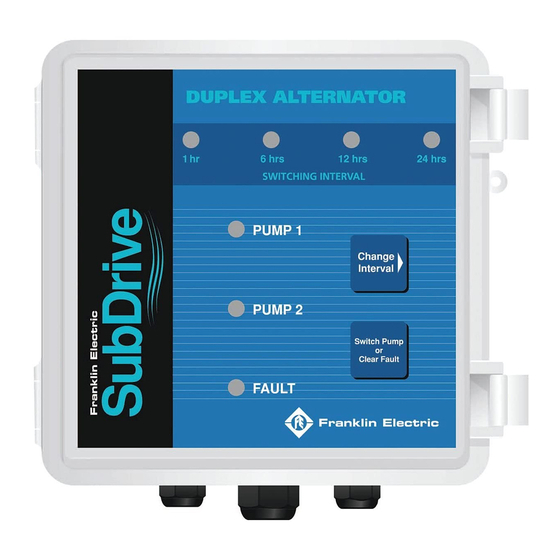
SubDrive Duplex Alternator 9. The Alarm Contacts are an optional feature. The Alarm Contacts are a set of dry contacts that close when the Alternator declares a fault. These contacts are rated for a maximum of 24 VAC at 1A (amps) or 24 VDC at 0.5A (amps). Any type of external alarm indicating load may be attached to these dry contacts as long as the maximum voltage and current criteria is not exceeded. - Page 14 SubDrive Duplex Alternator Setting the Alternate Time The alternate time is set by pressing the button labeled “Change Interval”. One press will move the orange indicator light over one position; each position is labeled with a different alternate time. When the primary system has...
-
Page 15: Mounting Dimensions
SubDrive Duplex Alternator Mounting Dimensions 5.80” 7.35” 5.80” 6.65” 4.70” 3.60” Accessories Duplex to Pressure Sensor Cable Kit - 22 AWG 4-conductor pressure sensor cable: 10 feet: 225597901 100 feet: 225597902 Drive to Duplex Cable Kit - 22 AWG 2-conductor pressure sensor cable:... -
Page 16: Diagnostic Fault Codes
SubDrive Duplex Alternator Diagnostic Fault Codes In the event that a problem occurs with one of the two Drive systems and the unit is unable to meet demand properly, the Alternator’s diagnostics will detect the problem and alert the user with a “Fault” light and close a set of dry contacts that can be connected to an external alarm. -
Page 17: Specifications
SubDrive Duplex Alternator Specifications Input from Power Source Voltage 115 VAC to Indoor/Outdoor Frequency 60 Hz Transformer Voltage 12 VAC Input to Controller Unit Frequency 60 Hz Power (A) 1.4 Watts Factory preset 50 psi Pressure Setting (B) Adjustment range... -
Page 18: Duplex Inline Constant Pressure Quick Reference Guide
SubDrive Duplex Alternator... - Page 19 Notes...
- Page 20 TOLL-FREE HELP FROM A FRIEND Franklin Electric Submersible Service Hotline 800-348-2420 400 East Spring Street, Bluffton, Indiana 46714 Tel: 260.824.2900 Fax: 260.824.2909 www.franklin-electric.com 225589101 REV 3 M1557 06-11 2 2 5 5 8 9 1 0 1...
Need help?
Do you have a question about the SubDrive Duplex Alternator and is the answer not in the manual?
Questions and answers