Table of Contents
Advertisement
Quick Links
Advertisement
Table of Contents

Summary of Contents for Riken Keiki TAN-5000
- Page 1 PT1E-1046 Buzzer Unit TAN-5000 Series Operating Manual...
-
Page 2: Table Of Contents
5-5. Description of operation ....................27 5-5-1. How to change alarm contacts ..................27 5-5-2. Maintenance mode ......................27 6 Measures for Abnormalities ....................28 7 Product Specifications ......................29 7-1. List of specifications ......................29 TAN-5000 - 1 -... -
Page 3: Outline Of The Product
Outline of the Product 1-1. Preface Thank you for choosing our buzzer unit TAN-5000 series for use with the RM-5000 series. Please check that the model number of the product you purchased is included in the specifications on this manual. -
Page 5: Important Notices On Safety
DANGER This is not an explosion-proof unit. Do not operate the buzzer unit in a place where combustible gases or vapors are present. Operating the buzzer unit in such an environment will lead to extreme dangers. TAN-5000 - 4 -... -
Page 6: Warning Cases
Turn the power switch OFF and cut the mains power before replacing a fuse. Do not use an unspecified fuse or short-circuit the fuse holder. For more information on fuses, please contact RIKEN KEIKI. • External connection Before connecting the buzzer unit to external equipments or external control circuit, securely connect it to a protective grounding circuit. -
Page 7: Precautions
• This is an electrical appliance. Be careful that it may be affected, in rare cases, by power supply noises, static electricity, and electromagnetic noises. Before using this product in an environment with such noises, provide for protective measures against them. TAN-5000 - 6 -... -
Page 8: Product Components
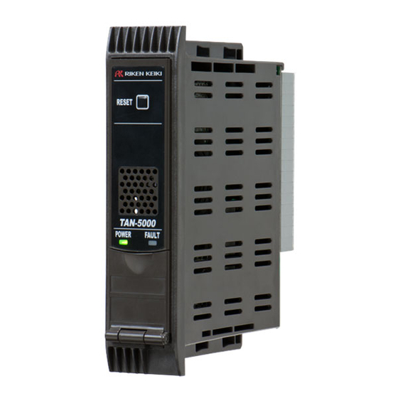
3 Product Components 3-1. Main unit and accessories Product Components 3-1. Main unit and accessories <Main Unit (TAN-5000 Series)> <Accessories> • Operating manual One copy per system regardless of the number of units to be delivered TAN-5000 - 7 -... -
Page 13: Block Diagram
3 Product Components 3-6. Block diagram 3-6. Block diagram Buzzer TAN-5000 Display (POWER) (FAULT) Power supply part Operating unit POWER INPUT (RESET) (BUZZER STOP) *1 (24 VDC) Controller (CPU) Alarm contact controller *1: The buzzer stop switch is mounted only if the alarm activation is the lock-in type. -
Page 14: How To Use
(infrared rays emitted from a high-temperature object), and where the temperature changes suddenly. Condensation may be formed inside the buzzer unit. Keep the buzzer unit (and its cables) away from noise source devices. When selecting installation points, avoid a place where high-frequency/high-voltage devices exist. TAN-5000 - 13 -... -
Page 15: Precautions For System Designing
Use a line filter to avoid the noise source noise. if necessary. Heat radiation designing When it is installed in the closed instrumentation board, attach ventilation fans above and below the board. TAN-5000 - 14 -... - Page 16 (100 VAC or below), and then protect the contact of the buzzer unit with an appropriate surge absorbing part, such as a CR circuit. TAN-5000 - 15 -...
-
Page 17: How To Wire
• It may be recommended that the surge absorbing part should be attached to the contact for certain load conditions. It must be attached to an appropriate position by checking how the load is activated. TAN-5000 Power Power supply... - Page 18 RS-485 function. The input-output from the indicator alarm unit passes through the buzzer unit. *3: Used for transition wiring for signals between devices when single-unit cases (option) are connected. When this connector is used, no transition wiring between cases is required at the terminal plate. TAN-5000 - 17 -...
- Page 21 (Do not pull the wire strongly.) if you insert the wire along the edge of the round hole. Removal: In the same way as for the wiring procedure, insert the screwdriver to remove the wire. TAN-5000 - 20 -...
-
Page 23: How To Operate
Preparation for start-up Power-on *1: Initial clear is activated on the indicator/alarm unit. Initial clear is not Initial clear (approximately 25 available on TAN-5000. seconds) *1 Press the reset switch. Detection mode Self-latching type: Press the reset switch to stop the buzzer sound and reset the <Gas alarm signal input>... -
Page 25: Description Of Operation
The common fault alarm contact is automatically reset after the system recovers from the fault status. NOTE The buzzer does not sound when a fault alarm is triggered <<Standard Setting>>. To enable sounding of the buzzer when a fault alarm is triggered, please contact RIKEN KEIKI. TAN-5000 - 24 -... - Page 26 ALM2 alarm lamp (red) Common first alarm contact Common second alarm contact Buzzer Pressing the reset switch * The operations of ALM1 and ALM2 alarm lamps shown in this chart are those of the indicator/alarm unit (option). TAN-5000 - 25 -...
- Page 27 Pressing the reset switch * The operations of ALM1 and ALM2 alarm lamps shown in this chart are those of the indicator/alarm unit (option). * Only gas alarm operation of the indicator/alarm unit is lock-in operation. TAN-5000 - 26 -...
-
Page 28: Description Of Operation
• After the adjustment is completed, do not forget to keep the reset switch pressed and return to the detection mode. If the buzzer unit remains in the maintenance mode, it automatically returns to the detection mode in ten hours. TAN-5000 - 27 -... -
Page 29: Measures For Abnormalities
• The cause can be either a failure of the buzzer unit or a failure of the external power supply. Find out the cause, take appropriate action, and then replace the fuse with a specified spare part. TAN-5000 - 28 -... -
Page 30: Product Specifications
7 Product Specifications 7-1. List of specifications Product Specifications 7-1. List of specifications [TAN-5000] Power display POWER lamp on or blinking (green) Gas alarm display Buzzer Gas alarm pattern Self-latching Gas alarm contact No-voltage contact 1a or 1b (2 step independent) - Page 31 External dimensions Approx. 29.6 (W) x 120 (H) x 92 (D) mm (projection portions excluded) Weight Approx. 80g * Specifications subject to changes without notice. * Only gas alarm operation of the indicator/alarm unit is lock-in operation. TAN-5000 - 30 -...
Need help?
Do you have a question about the TAN-5000 and is the answer not in the manual?
Questions and answers