Table of Contents
Advertisement
Quick Links
Operating and Installation
Manual
Barrett 4075 Linear Amplifier
BCM407500/10
© Barrett Communications
Head Office:
Barrett Communications Pty Ltd
47 Discovery Drive, Bibra Lake, WA 6163 Australia
Tel: +61 8 9434 1700 Fax: +61 8 9418 6757
Email: information@barrettcommunications.com.au
www.barrettcommunications.com.au
Advertisement
Table of Contents

Related Manuals for Barrett 4075

Summary of Contents for Barrett 4075
- Page 1 Operating and Installation Manual Barrett 4075 Linear Amplifier BCM407500/10 © Barrett Communications Head Office: Barrett Communications Pty Ltd 47 Discovery Drive, Bibra Lake, WA 6163 Australia Tel: +61 8 9434 1700 Fax: +61 8 9418 6757 Email: information@barrettcommunications.com.au www.barrettcommunications.com.au...
-
Page 2: Table Of Contents
BARRETT 4075 LINEAR AMPLIFIER - OPERATING & INSTALLATION MANUAL Contents Introduction ......................4 Terms and Abbreviations ....................4 Exploring the 4075 Linear Amplifier ................ 5 Front Panel ......................... 5 Keypad .......................6 Rear Panel .......................... 6 Switching the Linear Amplifier On / Off ..............8 Switching the Linear Amplifier On .................. - Page 3 BARRETT 4075 LINEAR AMPLIFIER - OPERATING & INSTALLATION MANUAL Installation and Setup .................... 23 Safety ..........................23 Getting Started ........................ 23 Mains Connection ......................23 Ground (Earth) System ....................25 Land System Grounding ...................25 Marine System Grounding ................26 Corrosion ....................26 Antenna Connection ......................
-
Page 4: Introduction
BARRETT 4075 LINEAR AMPLIFIER - OPERATING & INSTALLATION MANUAL Introduction The Barrett 4075 is a solid-state linear amplifier operating from 1.6 MHz to 30 MHz. It can be supplied with a power output level of either 500 watts or 1000 watts. -
Page 5: Exploring The 4075 Linear Amplifier
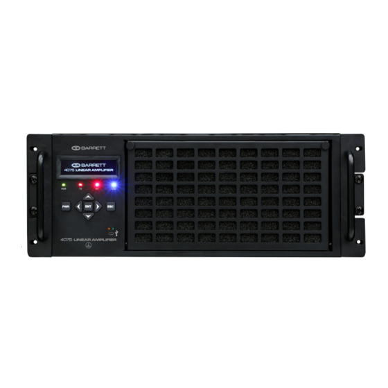
BARRETT 4075 LINEAR AMPLIFIER - OPERATING & INSTALLATION MANUAL Exploring the 4075 Linear Amplifier Front Panel PWR LED illuminates green when the unit is powered on. TX LED illuminates amber when the unit is transmitting (PTT on) OLED screen FLT LED illuminates red when the unit identifies a fault... -
Page 6: Keypad
BARRETT 4075 LINEAR AMPLIFIER - OPERATING & INSTALLATION MANUAL Keypad There are seven keys on the keypad. Some keys have multiple functions assigned to them depending on when the key is pressed and for how long the key is pressed. Key functions are listed below followed by a description of their functions. - Page 7 BARRETT 4075 LINEAR AMPLIFIER - OPERATING & INSTALLATION MANUAL RF Out 48 V for Amplifier Cooling fan /grill RF In 12 V Power Supply from 4022 2050 interface 4050 Breakout Box Interface Auxiliary input. Used if other equipment is far away. Alarms etc USB Interface.
-
Page 8: Switching The Linear Amplifier On / Off
BARRETT 4075 LINEAR AMPLIFIER - OPERATING & INSTALLATION MANUAL Switching the Linear Amplifier On / Off Switching the Linear Amplifier On Press to switch the unit BARRETT The Barrett splash screen dis- 4075 LINEAR AMPLIFIER plays. After two seconds the default... -
Page 9: Error States
BARRETT 4075 LINEAR AMPLIFIER - OPERATING & INSTALLATION MANUAL Error States There are three types of error states that may be encountered during opera- tion. These are: Warning The following message displays ERROR! accompanied by an audible WARNING alarm and a flashing red LED. -
Page 10: Display
BARRETT 4075 LINEAR AMPLIFIER - OPERATING & INSTALLATION MANUAL Display Main Menu From the Main Menu, Press either to move MAIN MENU 1 - Configuration Menu the selection up or down. 2 - Diagnostics Menu Press to select either the Configuration Menu or Diag- nostics Menu. -
Page 11: Exciter
BARRETT 4075 LINEAR AMPLIFIER - OPERATING & INSTALLATION MANUAL 1 - Exciter Use this option to select which exciter to use with the 4075 > Exciter MENU Linear Amplifier. 1 - Set 4050 2 - Set 2050 Alternative custom exciters 3 - Set Custom 1 (programmable) can be used. -
Page 12: Language
BARRETT 4075 LINEAR AMPLIFIER - OPERATING & INSTALLATION MANUAL 6 - Language N/A. Press to return to the previous menu. 7 - Other Select Other from the Config- uration Menu to display the > Other following. 1 - Buzzer Control... -
Page 13: Factory Reset
BARRETT 4075 LINEAR AMPLIFIER - OPERATING & INSTALLATION MANUAL Blocking Region Use this option to block pro- > BLOCKING REGION MENU grammable regions. Alterna- 1 - Region 1 2 - Region 2 tively, select none. 3 - Region 3 Select Blocking Region from the Other Menu to display the following. -
Page 14: Diagnostics Menu
BARRETT 4075 LINEAR AMPLIFIER - OPERATING & INSTALLATION MANUAL Diagnostics Menu A passcode is required to enter the Diagnostic menu. Select the Diagnostics menu from the Main Menu to display the Passcode screen. The passcode consists of four digits. The underscore rep- Passcode: 0000 resents the selected digit. - Page 15 BARRETT 4075 LINEAR AMPLIFIER - OPERATING & INSTALLATION MANUAL From the Diagnostics Menu, press either > DIAGNOSTICS MENU 1 - Clear Critical Error to move the selection up or 2 - Filter Control Menu down. 3 - Attenuation Control Press to select the re- quired menu.
-
Page 16: Clear Critical Error
BARRETT 4075 LINEAR AMPLIFIER - OPERATING & INSTALLATION MANUAL 1 - Clear Critical Error Select Clear Critical Error, when the error raising the alarm has been fixed. This will reset the Error State. See page 9 for further information. 2 - Filter Control Menu... -
Page 17: Attenuation Control
BARRETT 4075 LINEAR AMPLIFIER - OPERATING & INSTALLATION MANUAL 3 - Attenuation Control Select Attenuation Control from the Diagnostics Menu to > ATTENUATION CONTROL MENU display the following. 1 - Set 0dB Attenuation 2 - Set 3dB Attenuation Press to move... -
Page 18: Power Relay Control
BARRETT 4075 LINEAR AMPLIFIER - OPERATING & INSTALLATION MANUAL 4 - Power Relay Control Select Power Relay Control from the Diagnostics Menu to PS48vON/OFF: display the following. Enables or disables the external 48 V Power Supply. Press to toggle the selection on or off. -
Page 19: Pallet 0 Control
BARRETT 4075 LINEAR AMPLIFIER - OPERATING & INSTALLATION MANUAL 6 - Pallet 0 Control Select Pallet 0 Control from the Diagnostics Menu to display Pal0 ON/OFF: the following. The Power Amplifier consists of two pallets. Use this menu to enable or disable Pallet 0. -
Page 20: Pallet 1 Control
BARRETT 4075 LINEAR AMPLIFIER - OPERATING & INSTALLATION MANUAL 7 - Pallet 1 Control Select Pallet 1 Control from the Diagnostics Menu to display Pal1 ON/OFF: the following. The Power Amplifier consists of two pallets. Use this menu to enable or disable Pallet 1. -
Page 21: Fan Control Menu
BARRETT 4075 LINEAR AMPLIFIER - OPERATING & INSTALLATION MANUAL 8 - Fan Control Menu Select Fan Control from the Diagnostics Menu to display > FAN CONTROL MENU the following. 1 - FAN 0 Control 2 - FAN 1 Control The Fan Control menu enables... -
Page 22: Pump Control
BARRETT 4075 LINEAR AMPLIFIER - OPERATING & INSTALLATION MANUAL 9 - Pump Control Select Pump Control from the Configuration Menu to display Pump ON/OFF the following. Press to toggle the selection on or off. Press to display the Confir- mation screen. -
Page 23: Installation And Setup
Getting Started The new 4075 system is shipped with the Linear Amplifier removed from the rack. All other units are fitted and factory adjusted for optimum operation. All vacant slots are covered. - Page 24 For mains voltages 200 – 100 V AC, the mains supply cable has conductors of 4 mm By default, the cable type supplied with 4075 systems is for the higher mains voltage range. A special requirement needs to be ordered for low mains volt-...
-
Page 25: Ground (Earth) System
1/3 longer than the length of the antenna, buried to about 150 mm below the surface should be adequate. (Radial earth mat / ground plane: Barrett P/N BCA20026) Connection to metal water pipes can also improve the ground. On a roof top, there is usually not enough space for an adequate counterpoise. -
Page 26: Marine System Grounding
Wooden or fibreglass vessels present more of a problem to ground. Ideally the vessel should be fitted with an external copper ground sheet, connected to the interior of the vessel by suitable stud or an earth plate (“E” plate Barrett P/N BCA91700). -
Page 27: Antenna Connection
Amplifier. It is important that the “Antenna Type” selected within the “I/O Set- tings” menu of the Transceiver, is set to “4075 Linear Amplifier”. In this mode, the output power of the Transceiver is limited to between 30 W and 80 W, and the Automatic Level Control (ALC) voltage is sourced from the Linear Amplifier. -
Page 28: 4075 System Connections
BARRETT 4075 LINEAR AMPLIFIER - OPERATING & INSTALLATION MANUAL 4075 System Connections The BC407500 - 1000 W Transmitter may be located in an 18RU desk mounted rack cabinet or 39RU floor mounted rack cabinet. Power Distribution Power Unit Unit Speaker / Mic insert... -
Page 29: 4075 Connections - Rear View
BARRETT 4075 LINEAR AMPLIFIER - OPERATING & INSTALLATION MANUAL 4075 Connections - Rear View Internal rack cable connections are indicated in the following drawing: Linear Amplifier Power Supply (48 V) - Page 30 BARRETT 4075 LINEAR AMPLIFIER - OPERATING & INSTALLATION MANUAL IEC power cable C14 to C13 1m DE15F to DE15M cable 1.2m 4075 DC power cable Coax lead PL-259M to PL-259M DC power cable Accessories DC power cable 4075 Linear to PSU control cable...
-
Page 31: System Description
BARRETT 4075 LINEAR AMPLIFIER - OPERATING & INSTALLATION MANUAL System Description The 4050 Transceiver sends the transmission frequency to the Linear Amplifier which sets the appropriate low pass filter. In Standby (Receive) Mode (No PTT) In standby mode, the RF signal at the antenna bypasses the Linear Amplifier and goes straight to the Transceiver. -
Page 32: Operation Settings
In SSB mode, the transmitter will only produce power when modulation is pres- ent. The front panel of the 4075 Linear Amplifier can display both the forward power and VSWR via display menus (see page 8). The Linear Amplifier will not tolerate poor antenna matching when the VSWR is greater that 3:1. -
Page 33: Maintenance
If Selcall is enabled, send a Selcall to ensure the correct modulation to achieve full output power indication. Note: As the Transceiver’s antenna type has been set to “4075 Linear Amplifier“, if an external through-line power meter is used to measure the RF power out of the 4050 Transceiver, the Transceiver will NOT produce 125 W output power. -
Page 34: 4075 - Specifications
BARRETT 4075 LINEAR AMPLIFIER - OPERATING & INSTALLATION MANUAL 4075 - Specifications Please note these details are subject to change. General Specification Description Power Output CW 1 kW ± 1.5 dB Frequency Range 1.6 ~ 30 MHz Input Power for Rated Output 10 W... -
Page 35: Mechanical
BARRETT 4075 LINEAR AMPLIFIER - OPERATING & INSTALLATION MANUAL Mechanical Specification Description Dimensions excluding 178 x 482 x 480 mm (7” x 19” x 19” ) – H x W x D handles and I/O con- nectors Rack Height 4U, 19” Rack mount... -
Page 36: Connectors (Front)
BARRETT 4075 LINEAR AMPLIFIER - OPERATING & INSTALLATION MANUAL Connectors (Front) Specification Description Micro USB A/B System Interface – Status, BITE, Settings, Firmware upload Connectors (Rear) Specification Description UHF SO-239 (MIL-C-4914) RF Input Type N or 7/16 (option) RF Output... -
Page 37: Limited 3 Year Warranty Statement
Should any fault due to bad design, workmanship or materials be proven at any time within the warranty period, the company will rectify such fault free of charge providing the equipment is returned freight paid to Barrett Communications Pty Ltd head office or to an authorised service centre. The warranty period for all products is thirty six (36) months after date of shipment from the factory. -
Page 38: Warranty Registration And Technical Support
Please see contact details below. Once received your contact details will be registered against the serial numbers of your equipment and Barrett Communications will then be able to contact you if needed to keep you informed of any developments relating to your equipment. -
Page 39: Warranty Registration Contact Details
BARRETT 4075 LINEAR AMPLIFIER - OPERATING & INSTALLATION MANUAL Warranty Registration Contact Details By Mail The registration forms can be returned by mail, (no postage stamp required in Australia) Facsimile 08 9418 6757 (International +618 9418 6757) Email support@barrettcommunications.com.au Our customer / dealer technical support department can be contacted via land mail, email, telephone or with the support department contact form on the tech support web page. - Page 40 Barrett Communications Pty Ltd 47 Discovery Drive, Bibra Lake, WA 6163 Australia Tel: +61 8 9434 1700 Fax: +61 8 9418 6757 Email: information@barrettcommunications.com.au www.barrettcommunications.com.au...
Need help?
Do you have a question about the 4075 and is the answer not in the manual?
Questions and answers