Table of Contents
Advertisement
Quick Links
InteliVision 12Touch
InteliVision 12Touch OEM
SW version 1.4.0
Copyright © 2018 ComAp a.s.
Written by Ondrej Rais
Prague, Czech Republic
ComAp a.s., U Uranie 1612/14a,
170 00 Prague 7, Czech Republic
Tel: +420 246 012 111
E-mail: info@comap-control.com, www.comap-control.com
12,1" display unit for ComAp
Global Guide
controllers
5
10
14
15
20
51
63
Advertisement
Table of Contents

Related Manuals for ComAp InteliVision 12Touch


Summary of Contents for ComAp InteliVision 12Touch
-
Page 1: Table Of Contents
InteliVision 12Touch InteliVision 12Touch OEM 12,1" display unit for ComAp controllers SW version 1.4.0 1 Document information 2 System overview 3 Technical data 4 Installation and wiring 5 Graphical User Interface 6 Quick help 7 Custom configuration Copyright © 2018 ComAp a.s. - Page 2 4.1 Dimensions, Terminals and Mounting 4.2 Wiring diagrams 4.2.1 Earthing protection 4.2.2 InteliVision 12Touch and InteliSys Gas controller 4.2.3 InteliVision 12Touch and IGS-NT family controller 4.2.4 InteliVision 12Touch and InteliDrive DCU Marine controller 5 Graphical User Interface 5.1 GUI overview 5.1.1 Gestures 5.1.2 Dialogs 5.1.3 Pages...
- Page 3 6.10 Importing the firmware to the display unit 6.10.1 Firmware update using an import function in the display unit 6.10.2 Firmware update using an IVProg utility 6.11 State messages 7 Custom configuration InteliVision 12Touch & InteliVision 12Touch OEM Global Guide...
- Page 4 7.1 Custom logo 7.2 Setpoints help customization InteliVision 12Touch & InteliVision 12Touch OEM Global Guide...
-
Page 5: Document Information
AGREEMENT CONDITIONS – COMAP CONTROL SYSTEMS SOFTWARE” (License Agreement) and/or in the “ComAp a.s. Global terms and conditions for sale of Products and provision of Services” (Terms) and/or in the “Standardní podmínky projektů komplexního řešení ke smlouvě o dílo, Standard Conditions for Supply of Complete Solutions”... - Page 6 The full license texts and changes in the source code are available in an electronic form at ComAp and also may be sent to you upon your request in a hardcopy against payment of the shipping charge and costs. Modificated libraries are available on the ComAp website (www.comap.cz).
- Page 7 ComAp does not take any responsibility for the actions of persons responsible for cyber-attacks, nor for any damage caused by the cyber-attack. However, ComAp is prepared to provide technical support to resolve problems arising from such actions, including but not limited to restoring settings prior to the cyber-attacks, backing up data, recommending other preventive measures against any further attacks.
-
Page 8: General Warnings
EN 60945:03 - Maritime navigation and radiocommunication equipment and systems – General requirements - Minimal distance 80cm from the compass (valid only for InteliVision 12Touch OEM) Power supply VW 80101, part 3.14; ISO 16750-2 - Reset behaviour during voltage drop IEC 60533, part 7.2 - External power supply failure... -
Page 9: Document History
The number of the test report Certified laboratory Date 505059-01/01 EZÚ 23.12.2015 504383-01/01 EZÚ 6.1.2016 505059-01/03 EZÚ 27.1.2016 505059-01/02 EZÚ 23.2.2016 600885-01/01 EZÚ 31.3.2016 600885-01/02 EZÚ 31.3.2016 6 back to Document information InteliVision 12Touch & InteliVision 12Touch OEM Global Guide... -
Page 10: System Overview
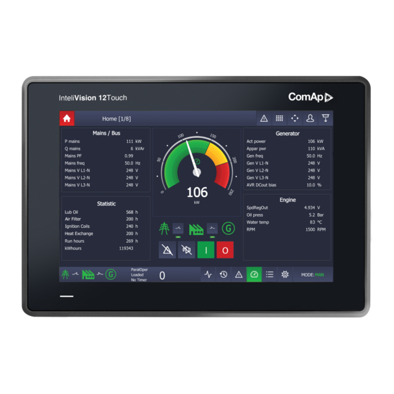
2.1 General description InteliVision 12Touch (InteliVision 12Touch OEM), industrial operator panel equipped with a 12,1” color, multi- touch screen, is dedicated together with the main ComAp controller to visualize and control single gen-set and drive controllers in various applications. InteliVision 12Touch (InteliVision 12Touch OEM) is a new generation display unit for ComAp , InteliGen NTC BaseBox,InteliGen NT BaseBox, InteliSys NTC BaseBox, InteliMains NTC BaseBox, InteliSys NTC Hybrid family of controllers, InteliDrive DCU Marine (HW version 2.0). -
Page 11: Connection To Pc
2.4.1 IVProg The InteliVision 12Touch display unit is programmed by the IVProg utility. It can be started from GenConfig PC tools or directly via menu start in Windows. The IVProg utility is included in the installation suite for a controller and it is installed automatically. -
Page 12: Image Manager
USB A-B cable, the IVProg utility can be started. There are 3 options how to start IVProg. From the Windows start menu (Start - All Programs - ComAp PC Suite - Tools - IVProg), using menu in GenConfig Software (File - Firmware Upgrade - InteliVision FW upgrade), or clicking on associated files of *.ivp... -
Page 13: Screen Editor
2.4.3 Screen Editor InteliVision 12Touch is distributed with the default metering screens. The screens are predefined in each configuration (archive). The User is able to modify the metering screens if necessary.The default screen template should cover most of the applications. -
Page 14: Technical Data
0 - 2400 Ohm Resistive input Accuracy 5% (Dedicated for external LCD backlight control) Binary outputs Isolated 0,5 A @ max. power supply voltage Overcurrent Mosfet Protection (Active when controller’s Horn output is activated) InteliVision 12Touch & InteliVision 12Touch OEM Global Guide... -
Page 15: Installation And Wiring
6 back to Table of contents 4.1 Dimensions, Terminals and Mounting InteliVision 12Touch can be mounted into the panel doors. Integrated holders are used for Display unit mounting. The recommended cut-out dimension for the unit is 311 x 206 mm (12.24 x 8.11 in). -
Page 16: Wiring Diagrams
Threads for grounding screws are marked by red bars on the picture below. Image 4.1 Earthing protection - grounding threads IMPORTANT: Each installed unit must be correctly grounded using the ground terminal placed on the back side of the chassis. InteliVision 12Touch & InteliVision 12Touch OEM Global Guide... -
Page 17: Intelivision 12Touch And Intelisys Gas Controller
4.2.2 InteliVision 12Touch and InteliSys Gas controller InteliVision 12Touch & InteliVision 12Touch OEM Global Guide... -
Page 18: Intelivision 12Touch And Igs-Nt Family Controller
(1). The setpoint RS485(1) conv. in the setpoint group Comms settings must be enabled. Note: InteliMains NTC BaseBox controller is also supported via ports RS-485(2) Note: InteliSys NTC Hybrid controller is also supported. InteliVision 12Touch & InteliVision 12Touch OEM Global Guide... -
Page 19: Intelivision 12Touch And Intelidrive Dcu Marine Controller
4.2.4 InteliVision 12Touch and InteliDrive DCU Marine controller Note: InteliVision 12Touch is supported from the InteliDrive DCU Marine 3.0.0 controller firmware. 6 back to Installation and wiring InteliVision 12Touch & InteliVision 12Touch OEM Global Guide... -
Page 20: Graphical User Interface
InteliVision 8 or InteliVision 5 display units. 5.1.1 Gestures InteliVision 12Touch uses gestures for configuring, moving, scrolling, commands and other functions. The Tap gesture is the most known gesture. The gesture is defined as click on the touch area. It is a standard gesture which can be used for clicking on the buttons, areas, cells, etc. -
Page 21: Dialogs
GCB breakers, Alarm and Horn reset, Start and Stop button). There are also Analog meter for Active power value, Power factor meter and Timer preconfigured on the system states values. Image 5.1 : Status screen preview InteliVision 12Touch & InteliVision 12Touch OEM Global Guide... -
Page 22: Status Bars
The top status bar can NOT be adjusted. The definition comes from the firmware and can not be user defined. All the information in the top status bar is fixed and controlled by ComAp. InteliVision 12Touch & InteliVision 12Touch OEM Global Guide... -
Page 23: Metering Screens
5.2 Metering screens Metering screens are dedicated for important controller values and setpoints. When the display is connected to the controller screen configuration is downloaded into the display. The concrete template of the screens InteliVision 12Touch & InteliVision 12Touch OEM Global Guide... -
Page 24: Intelivision 12Touch Controller Screens
5.2.1 InteliVision 12Touch controller screens InteliVision 12Touch controllers are predefined mainly for use in CHP applications at should cover most of this application type. The metering screens could be changed via powerful easy to use Screen Editor in GenConfig PC Tool. -
Page 25: Inteligen Ntc And Intelisys Ntc Controller Screens
Image 5.4 : Illustrative Metering screens for InteliVision 12Touch Combi application 5.2.2 InteliGen NTC and InteliSYS NTC controller screens InteliSys and InteliGen NTC BaseBox controllers are predefined mainly for use in standard applications and should cover most of this application type. The metering screens could be changed via powerful easy to use Screen Editor in GenConfig PC Tool. - Page 26 Image 5.5 : Illustrative Metering screens for InteliSys NTC BaseBox SPtM application InteliVision 12Touch & InteliVision 12Touch OEM Global Guide...
-
Page 27: Intelidrive Dcu Marine Controller Screens
4. Loadsharing (only in PRP application) 5. Statistic Note: Another screens are automaticly added If external modules, ECU modules and others are added using DriveConfig software. User is able to remove them manually if neccessary. InteliVision 12Touch & InteliVision 12Touch OEM Global Guide... -
Page 28: Trends
(see chapter Trends Settings). 6. Trend line - each channel can have different colour for better value identification. The color of the trend line match to the Value color in channel panel. InteliVision 12Touch & InteliVision 12Touch OEM Global Guide... - Page 29 The default ranges can cause a fragmented view of the trend window. IMPORTANT: If the trending is started it is not possible to make changes in the channel settings. The only graphical and export function is allowed in the trends settings dialog. InteliVision 12Touch & InteliVision 12Touch OEM Global Guide...
-
Page 30: Trends Settings
Trending in the background - if the trending in the background is active the samples are stored on a USB stick (if connected). The storing of the samples can be switched off even if a USB stick is connected, then the trends are stored only in the internal memory. InteliVision 12Touch & InteliVision 12Touch OEM Global Guide... -
Page 31: Channel Settings
7. Import - ensures the import the sets of samples from a USB stick to the internal memory. The trending must be stoped otherwise the function is not available because of the consistency reason. The only *.trd (ComAp proprietary format) file is supported for import. -
Page 32: History
System records - are also known as text history record. These type of records are generated during the user login/off or controller programming. Premortem record - is visually a different block of records generated just before the shutdown alarm Image 5.10 : History page InteliVision 12Touch & InteliVision 12Touch OEM Global Guide... -
Page 33: Row Filter
2. Event history checkbox - if the checkbox is checked the event history is displayed. 3. Premortem history checkbox - if the checkbox is checked The Premortem history is displayed. 4. System history checkbox - if the checkbox is checked the system history is shown. InteliVision 12Touch & InteliVision 12Touch OEM Global Guide... -
Page 34: Column Settings
Pressing the button opens the alarmlist page. The alarmlist page is displayed until the alarmlist contains the not confirmed alarms. There are 4 different types of controller alarms : InteliVision 12Touch & InteliVision 12Touch OEM Global Guide... - Page 35 5. Topstatus bar Alarmlist button - If there is an alarm in the controller The alarm button in the top statusbar starts blinking red. This is information that something is wrong and need to be checked. InteliVision 12Touch & InteliVision 12Touch OEM Global Guide...
-
Page 36: Ecu Alarmlist
The setpoint page is intended for setting the controller values. Each type of controller has specific setpoints to be set. The setpoints also depend on the type of application like SPtM, SPI, MINT, COMBI, COX (see the concrete manual of the requested controller for available setpoints to be set). InteliVision 12Touch & InteliVision 12Touch OEM Global Guide... -
Page 37: Administration
6. Setpoints button - by pressing this button from the entire GUI displays of the Setpoints page. 5.7 Administration 5.7.1 Users & Passwords 5.7.2 Communication 5.7.3 Languages 5.7.4 InteliVision Info 5.7.5 Controller Info 5.7.6 InteliVision Settings 5.7.7 Export & Import InteliVision 12Touch & InteliVision 12Touch OEM Global Guide... -
Page 38: Users & Passwords
InteliDrive controllers (compared to the InteliSys GAS, InteliGen and InteliSys based controller) have different user management. InteliDrive based controllers have 1 unlogged user password level with access rights 0 and another 3 user password level with the access rights 1,2, or 3. InteliVision 12Touch & InteliVision 12Touch OEM Global Guide... - Page 39 Image 5.17 : Administration Page - Users & Passwords for InteliDrive controllers Note: The Administration - Users & Passwords page style is automatically selected based on the connected controller. InteliVision 12Touch & InteliVision 12Touch OEM Global Guide...
-
Page 40: Communication
3 up to 5 terminal addresses for one CAN bus line based on the controller to which the user want to connect InteliGen BaseBox, InteliSys BaseBox and InteliVision 12Touch based controllers have 4 available terminal adresses InteliDrive DCU based controllers have 5 available terminal adresses... - Page 41 Different History reading process if the ethernet interface is selected the whole history is read just after the configuration is downloaded (like in InteliMonitor PC application) Image 5.20 Ethernet connection - DHCP mode InteliVision 12Touch & InteliVision 12Touch OEM Global Guide...
- Page 42 2. Controller IP address - by pressing the cell area the dialog for the controller IP addresses insert is displayed. The Controller IP address can be found and set via the controller setpoints. The controller IP address is the address where the InteliVision 12Touch will be trying to connect. Be sure there is no address collision.
- Page 43 IMPORTANT: Be sure there is no IP address collision before you try connect to the controller using ethernet interface. IMPORTANT: Before the first usage of the InteliVision 12Touch 1.4.0 with fixed IP connection option the Connect button must be pressed before attempt for controller autodetection. This is because the IP address, SubNet mask settings must be validated by the InteliVision 12Touch operating system.
-
Page 44: Languages
Note: The GUI languages does not mean the languages in the controller configuration. Note: InteliVision 12Touch can show common code pages (437, 708, 720, 737, 775, 850, 852, 855, 857, 858, 860, 861, 862, 863, 864, 865, 866, 869, 874, 932, 936, 949, 1250, 1251, 1252, 1253, 1254, 1255, 1256, 1257, 1258, 20127, 20261, 20269, 20866, 21027, 21866, 28591, 28592, 28593,28594, 28595, 28596, 28597, 28598, 28599,28603, 28605, 29001). -
Page 45: Intelivision Info
5.7.4 InteliVision Info Image 5.23 : Administration Page - InteliVision Info 1. InteliVision 12Touch details - the list of information about the display unit (SW version, HW version, Branch, Release date, etc.) InteliVision 12Touch & InteliVision 12Touch OEM Global Guide... -
Page 46: Controller Info
Note: The ID chip info is displayed as binary value (with LSB on the left side). PC tool InteliMonitor displays the same value in hexadecimal form. E.g. : InteliVision 12Touch - 1000000001000000; InteliMonitor - 0x0201 5.7.6 InteliVision Settings Image 5.25 : Administration Page - InteliVision Settings... - Page 47 (approximately 30 minutes) during the normal running genset or engine phase. It is because of saving lifetime of the display unit. The display unit is still running if the backlight is off. For switching on the LCD backlight the simple gesture tap is necessary. InteliVision 12Touch & InteliVision 12Touch OEM Global Guide...
-
Page 48: Export & Import
*.csv file is supported. b. Logo - the user is able to save the actual logo (ComAp eyes) on a USB Stick. The USB stick must be plugged in. The logo will be saved as logo.png to the specific directory on a USB stick. - Page 49 *.ivi is created in the specific directory on a USB stick. e. Clone - the clone is the complete copy of the entire InteliVision 12Touch unit. The display unit will export the clone to the *.ivc file. The feature is intended for installations or applications where similar display units are used.
-
Page 50: Service Screen - Administration
The service screen is a special screen which can be adjusted using the powerful easy to use Screen Editor in GenConfig PC Tool. By default the service screen is predefined by general information. 6 back to Graphical User Interface InteliVision 12Touch & InteliVision 12Touch OEM Global Guide... -
Page 51: Quick Help
InteliMains NTC BaseBox (3.5.0) InteliMains NT BaseBox (3.5.0) InteliSys NTC Hybrid (2.0.0) InteliDrive DCU Marine (3.0.0) The table above shows the controller interfaces which are supported and can be used for connection with InteliVision 12Touch. InteliVision 12Touch & InteliVision 12Touch OEM Global Guide... - Page 52 5. Choose the correct terminal address (for CAN interface only). 6. Press the Connect button. If the cabling and settings are right, the display unit InteliVision 12Touch will start to download the configuration from the controller to the display. Note: If the display does not start with the downloading of the configuration from the controller try to check the wiring of RS-485 cables, check if the correct interface is selected, check the termination resistors on both ends, check the right controller address, check if the free terminal address is selected.
-
Page 53: Logging In/Off To The Controller
IMPORTANT: InteliVision 12Touch supports only the newest controller archives (InteliVision 12Touch templates included) !!! IMPORTANT: If the communication between InteliVision 12Touch and the controller is lost for some reason the display will try to re-establish communication twice, then the communication error appears and limited GUI is displayed. -
Page 54: Important Values
(status screen button). Image 6.5 : Important values Note: Metering screens and bottom status bar are user adjustable using the powerful easy to use Screen Editor in GenConfig or DriveConfig PC Tool. InteliVision 12Touch & InteliVision 12Touch OEM Global Guide... -
Page 55: Gen-Set Mode Change
Note: The out of range setpoint image is displayed as a red field in the cell with the value. There is also a red dot in the top right hand corner of the concrete group. InteliVision 12Touch & InteliVision 12Touch OEM Global Guide... -
Page 56: Password Change
IMPORTANT: Each user can change only his own password. The only administrator can RESET the password to other users. 6.7 Display brightness settings The display brightness setting is adjustable using the Administration Menu - InteliVision Settings. InteliVision 12Touch & InteliVision 12Touch OEM Global Guide... -
Page 57: Alarms Types
Shutdown (often also known as 2nd level alarm) - represented by the RED colour. These types of alarms protects the GenSet or Engine against the wrong status. ECU alarm - represented by the BLUE colour. This type of alarm comes from the ECU units. InteliVision 12Touch & InteliVision 12Touch OEM Global Guide... - Page 58 Note: The Alarmlist page is automatically displayed if the new alarm appears and the actual GUI position is Home metering screen.. By confirmation using the button Alarm-reset the Home page is displayed. IMPORTANT: InteliVision 12Touch shows a maximum of 16 alarms. InteliVision 12Touch & InteliVision 12Touch OEM Global Guide...
-
Page 59: Communication Issues
Image 6.12 : Communication error When the cause of the problem is removed the communication error disappears, but the gray inactive icon of lost communication in the top status bar stays visible until the next restart. InteliVision 12Touch & InteliVision 12Touch OEM Global Guide... -
Page 60: Importing The Firmware To The Display Unit
InteliVision 12Touch igc package. Then the InteliVision12Touch_xxxx.ivp firmware is stored in your harddrive automatically into the directory c:\Users\Public\Documents\ComAp PC Suite\Tools\IVProg\ ii. Simply put your USB Stick to the InteliVision 12Touch display unit.The directory InteliVision12T and its subfolders are created automatically. The subfolder name which is dedicated for the firmware update is InteliVision12T/Application. -
Page 61: Firmware Update Using An Ivprog Utility
The actual firmware (*.ivp) stored in the display unit is exported to your USB Stick - folder InteliVision12T/Application. Note: Once the USB stick is inserted to the display unit the InteliVision 12Touch directory is created automatically. IMPORTANT: Requested files to be imported must be saved in the specific directory on a USB Stick. -
Page 62: State Messages
Unsupported bitmaps format. (Engine, gen-set and etc...) Firmware upgrade Bitmaps format not supported Error is necessary. Default/Defined language error/not supported. Language change or code Default lang. not supported Error page change is necessary. 6 back to Quick help InteliVision 12Touch & InteliVision 12Touch OEM Global Guide... -
Page 63: Custom Configuration
These numbers could be changed onto whatever you want. But be aware that ComAp does not support any misunderstanding on the custom specific description. All description is up to the user. See the instruction below on how to customize the setpoint description. - Page 64 3. Wait until the configuration table is loaded. Then you are able to export hints. 4. Insert the USB stick into the InteliVision 12Touch. 5. Go to the administration menu Import/Export. Press the hint button in the Export Column. The file hints.ivts is exported onto your USB stick into the hint folder.
- Page 65 17. Rename the compressed zip file to the hints.ivqm file. 18. Now you are ready to import the hints.ivqm package back to the InteliVision 12Touch. 19. Copy the file hints.ivqm into the USB flash drive into the specific folder (Intelivision12T/Hints), which is the same folder where you found the exported hints.ivts file.
Need help?
Do you have a question about the InteliVision 12Touch and is the answer not in the manual?
Questions and answers