Advertisement
Quick Links
LIQUID INSTALLATION GUIDE
875-3000-100 Rev A1
Overview:
This installation guide lists all the parts in the
IntelliFlow 3 (IF3) liquid kits and provides instructions on how to install
the IF3 components, associated cables, and switches.
Read this manual thoroughly before beginning the installation.
If you have any questions, contact your local dealer or Satloc Customer Service.
IntelliFlow 3 Liquid Installation Guide
1
875-3000-100 Rev A1
Advertisement

Related Manuals for Satloc INTELLIFLOW 3

Summary of Contents for Satloc INTELLIFLOW 3
- Page 1 875-3000-100 Rev A1 Overview: This installation guide lists all the parts in the IntelliFlow 3 (IF3) liquid kits and provides instructions on how to install the IF3 components, associated cables, and switches. Read this manual thoroughly before beginning the installation.
- Page 2 Enter desired rates through the GPS interface, and the IF3 system will regulate and maintain selected rates. Once installed, the G4 or Bantam GPS controls the IntelliFlow 3™ system settings. Spray rates are automatically cont rolled with an accurate constant flow rate or a variable rate based on application selections or prescription maps (PMAPs) in the GPS system.
-
Page 3: Safety Information
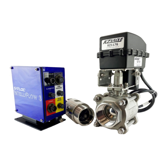
Satloc is dedicated to providing updated versions of installation guidebooks for its customers. Scan the QR code to verify you have the latest version of the IntelliFlow 3 Liquid Installation Guide or click this link to make sure this is the latest version _____________. - Page 4 PARTS COVERED BY THIS INSTALLATION GUIDE This guide is applicable to all IntelliFlow 3 liquid installations for both G4 and Bantam and covers all IntelliFlow 3 kits. Each table describes the parts that may be included in your installation. Table 1: Flow Meters...
- Page 5 Table 3: IntelliFlow 3 Liquid Installation Parts 050-2509-000 050-2508-000 054-0101-000 050-2503-000 Power Cable Bantam IF3 Cable IF3 Motor Cable G4 IF3 Cable (1) (black and white cable) Connects part I’s POWER cable to (1) (red cable) (1) (red cable) (1) (red cable) aircraft power source, see item K Connects part I’S CONTROLLER to...
-
Page 6: Controller Installation
Use parts Pd, Pe, and Pf to attach vibration isolators (Part Pc) to approved structure. vi) Use parts Pa and Pb to attach vibration mounts to horizontal mounting brackets (Part O). IntelliFlow 3 Liquid Installation Guide 875-3000-100 Rev A1... - Page 7 Store excess cable lengths with a minimum six-inch bend radius. • Do not coil cables (introduces noise). • Avoid high-temperature exposure (for example - the exhaust, exhaust manifold) when routing. • Hand tighten connections only; do not use tools (overtighten). • IntelliFlow 3 Liquid Installation Guide 875-3000-100 Rev A1...
- Page 8 Install the flow meter and valve/motor assembly in the aircraft’s existing boom supply tube. Figure 2 shows the recommended configuration of IntelliFlow 3’s flow meter and valve/motor assembly. If you cannot install the flow meter and valve/motor vertically (as shown) because of the physical limitations of the aircraft, you may vary the rotational position of either as required.
- Page 9 • Flow meter to the valve/motor assembly • Valve/motor assembly to the boom 2. Secure the hoses using two clamps at each connection. This now constitutes the ‘IntelliFlow 3 assembly’ . 3. Attach the IntelliFlow 3 assembly to the boom supply plumbing.
-
Page 10: Technical Support
Technical Support IntelliFlow 3 Liquid Installation Guide 875-3000-100 Rev A1...
Need help?
Do you have a question about the INTELLIFLOW 3 and is the answer not in the manual?
Questions and answers