
Summary of Contents for LEM Sentinel 2
- Page 1 BATTERY MANAGEMENT S-BUS (SENTINEL 2, I-LINK 2, S-BUS CONVERTER) USER GUIDE N°98.60.17.013.0 1/ 19 080424/1...
- Page 2 REVISIONS Document Sentinel Date Evolution version Firmware V 0.0 V1.10, 2007-11- Creation V1.11 V1.10, 2008.04.09 Added LEM address (page 4) + modified power V1.11 supply in range (page 8) and Additional input power supply (page 9) N°98.60.17.013.0 2/ 19 080424/1...
-
Page 3: Table Of Contents
TABLE OF CONTENTS NOTICES ........................4 SAFETY INSTRUCTIONS.....................4 1.1.1 Qualified personnel.......................4 1.1.2 Safe operation ......................4 1.1.3 Maintenance and repairs ....................4 1.1.4 Ce marking........................4 GENERAL DESCRIPTION....................5 COMMUNICATION .......................6 SENTINEL DEVICE ......................7 I-LINK DEVICE......................8 S-BUS CONVERTER....................9 PROTOCOL........................10 COMMAND .........................10 RESPONSE ........................12 SPECIFIC I-LINK COMMANDS & RESPONSES ............15 INSTALLATION ......................17 SYSTEM CONNECTIONS ..................17 SEQUENCE FOR A NEW SENTINEL OR I-LINK INSERTION........18... -
Page 4: Notices
MicroGuard. Such network is based on S-Bus communication, protocol supported by LEM Sentinel-2 and I-Link-2 devices on the S-Bus and I-Bus communication links, respectively. Both are connected to any OCS (Overview and Control System) serial port through LEM RS232 to S-Bus converter. -
Page 5: General Description
I-Link module. Only use the accessories supplied with such devices, specifically available for your equipment (see table below). DESCRIPTION PART (CLEM) Numbers Sentinel 2 - LV, 2V 66.61.05.000.0 Sentinel 2 - HV, 6-12V 66.61.14.000.0 I-Link 2 66.82.98.000.0 S-Bus converter 66.81.98.001.0... -
Page 6: Communication
2.1 Communication The LEM proprietary communication bus is generally referred to as S-Bus or I-Bus, dedicated link for I-Link modules. In practice, both have exactly same characteristics and function in the same way. Based on serial full duplex communication, each device has an unique ID, 001-254, which identifies it on the appropriate bus. -
Page 7: Sentinel Device
2.2 Sentinel device The Sentinel device is a digital transducer, which measures Voltage, Temperature and Impedance of a 'Standby' Battery. Two types of modules exist: one for low voltage 2V bloc, another one for high voltage (6V or 12V). Mechanical drawings: The module is equipped with two S-Bus ports (refer front view), internally connected in parallel and with a power &... -
Page 8: I-Link Device
2.3 I-Link device The I-Link device is attached to a LEM current transducer (CT) whose output signal is measured and converted, for the purposes of transmission over the I-BUS. It is designed to accommodate up to 2 current sensors: a combined charge/discharge sensor, and a separate ‘float’... -
Page 9: S-Bus Converter
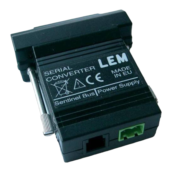
All the data sheets are available on LEM web-site. 2.4 S-Bus converter The S-Bus converter is designed to convert the LEM proprietary Sentinel & I-Link communication bus (S-Bus) to RS232 interface. Note, the module only acts on signal levels conversion, no software protocol translation is performed. -
Page 10: Protocol
3 PROTOCOL 3.1 Command The Sentinel or I-Link unit expects commands from another compatible device such as a system controller attached to the network to be issued to it in 3 - byte packets, sent in big- endian format (MSB first) and accepts: all commands with its unique ID, some commands (see below) with a broadcast ID (=255) designated as global which is destined for all units on the network. - Page 11 Command set for Sentinel devices: byte2 value meaning 0x40 Measure Voltage and store value 0x41 Measure Temperature and store value 0x42 Measure Impedance and store value 0x20 Transmit Voltage from stored value 0x21 Transmit Temperature from stored value 0x22 Transmit Impedance from stored value 0x60 Measure and Transmit Voltage (+storage) 0x61...
-
Page 12: Response
4) Impedance test takes 6 seconds to complete, from when instruction is received. During this period, it is recommended to not communicate with any unit on the bus. In case of an Impedance measurement is in progress, any new incoming MEASURE command aborts the sequence and the unit executes the new command. - Page 13 Within the 2 Data bytes, these 15 bits are organized as follows: bit 7 (MSB) General flag bit 6 Exp #3 (MSB) Data A bit 5 Exp #2 (byte 2) bit 4 Exp #1 bit 3 Exp #0 (LSB) bit 2 Man #10: 2^ (-1) (MSB) bit 1 Man #9: 2^ (-2)
- Page 14 Parameter Data A, Data B Flag, Exp, Mant Value Voltage 0x55, 0xA0 0 1010 10110100000 13.625 V Voltage 0x41, 0x00 0 1000 00100000000 2.25 V Temperature 0x69, 0xD0 0 1101 00111010000 78.5 °F Impedance 0x3C, 0x80 0 0111 10010000000 1.5625 mO Sentinel unit transmits “Infinite”...
-
Page 15: Specific I-Link Commands & Responses
Conditions for issuing a READY announcement: Either of the following conditions needs to met: • the value of the ID register, hold in non-volatile memory, is 0 - indicating a virgin/unassigned Unit • the status of the RESET flag is Active - indicating a Reset was requested by the OCS. On receiving a command to Reset, the Sentinel unit asserts the RESET flag prior to perform a soft-reset. - Page 16 Method to decode the Data: Return data format is still IEEE754 half-floating point, unsigned with Mantissa defined on 11 bits and exponent on 4 bits (same as for Sentinel returned values). Anyway the decimal value is limited to range (0-10). Moreover, for the Charge/Discharge value, it must be then shifted to range <–5 to +5>...
-
Page 17: Installation
S-BUS link length in less than 20 m. 5. Install the LEM current transducer on the main positive cable from the battery. Observe correct current flow: the arrow on top of the transducer indicates positive current, so it... -
Page 18: Sequence For A New Sentinel Or I-Link Insertion
At this step, the Sentinel modules must not (yet) be connected to the Battery. All the units are already connected to each other in a 'daisy-chain' manner using LEM short communication cables (S-Bus), then to S-Bus converter, which itself is linked to the Host serial port:... - Page 19 step3) The unit will respond with actual ID to 0, by asking for the new ID : Host <<<<< Sentinel : 00 A0 00 A0 Byte1 is the ID of the unit: 0 in this case. Byte2, byte3 are data: 0xA0 for “Send ID”, 0x00 for unused byte. Byte4 is the Checksum step4) Immediately, the controller must send the new ID in the following command:...
Need help?
Do you have a question about the Sentinel 2 and is the answer not in the manual?
Questions and answers