
Summary of Contents for L2G VULCAIN-2/3
- Page 1 FOURS MIXTES A INJECTION DE VAPEUR VULCAIN-2/3, VULCAIN-4, VULCAIN-5, VULCAIN-6, VULCAIN-7, VULCAIN-10 Rev. 1_2016 - del 10/2016 Cod. LINERMIDN...
- Page 2 Welcome Thank you for choosing one of our products. Please read this User and Maintenance Manual carefully to ensure optimal use of the Oven. ENGLISH WEEE - waste electrical and electronic equipment The crossed bin symbol on the product or on the user manual documentation indicates that the product has been put onto the market after the date of 13th August 2005.
-
Page 3: Table Of Contents
TABLE OF CONTENTS INTRODUCTION page 28 USING THE MANUAL page 28 KEEPING THE MANUAL page 28 DESCRIPTION page 29 1. POSITIONING page 30 1.1 TRANSPORTAION page 30 1.2 OFFLOADING/DIMENSIONS /WEIGHTS page 30 1.3 PACKAGING page 30 1.4 POSITIONING page 30 1.5 MINIMUM WALL DISTANCES page 31 1.6 FEET POSITIONING AND ADJUSTMENT... -
Page 4: Using The Manual
INTRODUCTION Original instructions The “VULCAIN OVENS” has been constructed in respect of the overall community norms concerning the free circulation of industrial and commercial products in EU countries. Before proceeding with all the operations on the products, it is recommendable to read carefully the user’s manual and maintenance. -
Page 5: Description
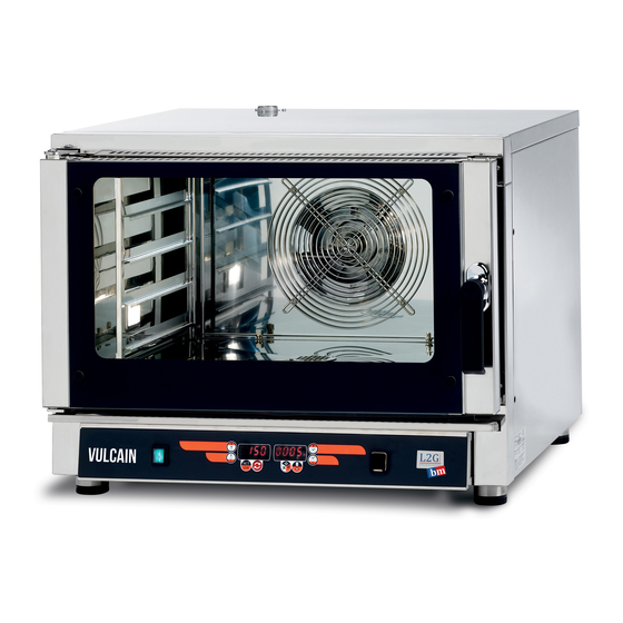
DESCRIPTION This user manual refers to "CONVECTION/STEAM OVENS" of the MID line for professional use, for cooking food and dishes in the versions with electrical power supply Types of cooking CONVECTION COOKING: CONVECTION PLUS FAN HEATING ELEMENT The oven is equipped with mechanical ventilation that allows an even distribution of the hot air within the cooking chamber DELTA-T COOKING (optional): Cooking that keeps constant the difference between oven chamber temperature and that of the core probe. -
Page 6: Positioning
1. POSITIONING Before offloading/loading and positioning the product, you are kindly invited to carefully read this manual espe- cially the chapters regarding offloading/loading, lengths, dimensions and weights of the oven. 1.1 TRANSPORTATION We recommend you to transport the Oven always in the upright position (as mention on the packing). -
Page 7: Feet Positioning And Adjustment
1.6 FEET POSITIONING AND ADJUSTMENT Place the oven perfectly upright, adjusting if necessary the screw feet of the legs of the appliance to adjust the level. Check evenness with a spirit level. The oven must be placed on a perfectly flat surface in order to work properly and to allow correct water drainage. -
Page 8: Connecting The Equipotential Terminal
2.2 CONNECTING THE EQUIPOTENTIAL TERMINAL Connect the oven to earth and insert it in the equipotential circuit. The terminal used for this purpose is located at the rear of the oven, and is marked by the international symbol shown in the figure. 2.3 CONNECTING THE POWER SUPPLY CABLE 1/A) Loosen the 4 screws holding the lid of the electrical board compartment and open it 1/B) Pass the power cable into the cable gland on the lid and compress it... -
Page 9: Connection To The Mains Water
3.3 CONNECTION TO THE MAINS WATER • connect the oven to the mains water supply (drinking water) using flexible pipes and fittings with 3/4 connectors. ATTENTION The supply water pressure must be between 1.5bar and 2.5 bar. It is advisable to use an inlet water softening system to keep the water hardness below 3°F. Calcification of the components due to not using a decalcification system involves technical operations not covered by the oven warranty. -
Page 10: Cleaning The Cooking Chamber
CLEANING THE COOKING CHAMBER After every cooking process, depending on the use of the oven, the muffle (cooking chamber) must be cleaned from any food or grease residues; For cleaning the oven, use a suitable degreasing product, the indications, use instructions and warnings of which must be followed. -
Page 11: Product Loading And Use
or after that the latter have received instructions relating to the safe use of the appliance and in understanding of the dangers involved with it Children must not play with the appliance. Cleaning and maintenance to be carried out by the user must not be performed by children without supervision. Always keep away from the appliance during operation, when opening the door. -
Page 12: Maintenance
6. MAINTENANCE All maintenance operations and repairs must be carried out with the unit in stop position and with the power switched off. When parts are being replaced and when removal of the plug is foreseen, and removal of the plug is clearly indicated, it must be such that an operator may check, from any point to which he has access, that the plug remains disconnected. -
Page 13: Removing/Replacing The Internal Glass
6.3 REMOVING/REPLACING THE INTERNAL GLASS In case of damage and/or replacement of the front glass, recover the glass fragments avoiding disposing of them in the environment. Exert caution after any possible breakage of the glass. manoeuvre it with care and avoid cutting yourself. -
Page 14: Oven Door Fitting And Replacement
6.4 OVEN DOOR FITTING AND REPLACEMENT Switch-off the oven and disconnect it from the electrical network. Wait for it to cool. ATTENTION Pay attention when removing the appliance door as it is heavy! It is advisable to remove the oven door and position it delicately on a surface according to the following instructions. 1A/B) Remove the back panel (A) and then the oven door hinge side panel (B). -
Page 15: Removing The Racks (Tray Holders)
6.5 REMOVING THE RACKS (TRAY HOLDERS) Switch-off the oven and disconnect it from the electrical network. Wait for it to cool. 1) Lift the side rack by a few centimetres, freeing it from the 2 latches that secure it at the bottom of the cook- ing chamber. -
Page 16: Fan Casing Dismantling And Fan Removal/Replacement
6.7 FAN CASING DISMANTLING AND FAN REMOVAL/REPLACEMENT Switch off the oven and disconnect it from the electrical network. Wait for it to cool and the fan to stop. 1) Lift the rack by a few centimetres from the side where lamp to be replaced is located, freeing it from the 2 latches that secure it at the bottom of the baking chamber (Picture 1 paragraph 6.5). -
Page 17: Replacing The Heating Elements
6.9 REPLACING THE HEATING ELEMENTS Switch-off the oven and disconnect it from the electrical network before replacing the motorfan. 1) Lift the rack by a few centimetres from the side where lamp to be replaced is located, freeing it from the 2 latches that secure it at the bottom of the baking chamber (Picture 1 paragraph 6.5). -
Page 18: Waste Management - Disposal Of Materials
7. WASTE MANAGEMENT - DISPOSAL OF MATERIALS 7.1 DISPOSAL OF MATERIALS AND WASTE MANAGEMENT The electrical and electronic equipment that make up the appliance, such as lamps, electronic control, electric switches, electric motors, and other electrical equipment in general, must be disposed of and/or recycled separately from the municipal waste according to the procedures of the rules in force in each Coun- try. -
Page 19: Mechanical Control Panels
8. PANNELLI COMANDO MECCANICI MECHANIC CONTROL PANELS PANNEAU DE COMMANDE MÉCANIQUE MECHANISCHE REGLER PANEL DE CONTROL MECÁNICA لوحات التحكم الميكانيكية LEGENDA / LEGEND مقبض درجة الحرارة MANOPOLA TEMPERATURA TEMPERATURE KNOB BOUTON TEMPÉRATURE TEMPERATURKNOPF ضوء بيان للمقاومة SPIA RESISTENZA LIGHT VOYANT LICHT HEIZELEMENTE "HEATER ELEMENTS"... -
Page 20: Digital Control Panel
9. DIGITAL CONTROL PANEL DIGITAL VULCAIN OVENS - MID The user interface is the front of the instrument, provided with - 8 buttons - 2 9mm 4 digit display, for the symbolic or numeric display of the resources in question plus 14 LED icons for visual indication of states or alarms. - Page 21 Keypad The keypad has 8 keys. The main functions of each key are outlined below. The keys may have secondary features determined by pressing them together with other keys and by length of pressing. Function POWER 0 / 1 TEMPERATURE REDUCTION TEMPERATURE INCREASE ON/OFF - SET PARAMETERS START/PAUSE COOKING CYCLE...
- Page 22 Manual parameters setting In this mode it is possible to directly set the cooking parameters and start the work cycle. 4 parameters can be set: Cooking temperature Cooking time Stop probe temperature (if installed) Amount of water flow (through the percentage of the injection cycle) (if installed) After these settings, the oven allows starting of a preheat cycle "PRE"...
- Page 23 and time). (temperatures and times). In fact pressing the right UP DOWN scroll keys moves between the various recipes (the recipes already set are displayed and only the first one blank). Having selected a recipe, wait- ing, its parameters will be displayed cyclically. If a recipe is not yet set, the oven will display 0 on both the displays. Setting a recipe To set a recipe, once the recipes mode has been activated with the described mode, simultaneously press and hold the right UP...
- Page 24 Cooking Cycle At this phase the actual cooking takes place which will end either at the relevant time or tem- perature, depending on the selection made. Pressing the right UP DOWN or left UP DOWN keys will reset the cooking parameters as already described except for the fact that instead of "Preheating"...
- Page 25 NOTES...
- Page 26 Bienvenue Nous vous remercions d'avoir choisi l'un de nos produits. Nous vous invitons à lire attentivement ce manuel d'utilisation et d'entretien pour vous assurer l'utilisation optimale du Four. ITALIANO RAEE - Gestione rifiuti apparecchiature elettriche ed elettroniche Il simbolo del bidone barrato posto sul prodotto o sulla documentazione del manuale d’uso, indica che il prodotto è stato immesso nel mercato dopo la data del 13 agosto 2005.
- Page 27 INDEX INTRODUCTION p. 52 UTILISATION DU MANUEL p. 52 CONSERVATION DU MANUEL p. 42 DESCRIPTION p. 53 1. EMPLACEMENT p.54 1.1 TRANSPORT p. 54 1.2 DECHARGEMENT / DIMENSIONS / POIDS p. 54 1.3 EMBALLAGE p. 54 1.4 POSITIONNEMENT p. 54 1.5 DISTANCES MINIMALES PAR RAPPORT AU MUR p.
- Page 28 INTRODUCTION Instructions traduites de l'Italien Les « FOURS VULCAIN » ont été construits conformément aux nomes globales de la communauté concernant la libre circulation des produits industriels et commerciaux dans les produits de l'Union Européenne. Avant de procéder à toutes les opérations sur les produits, il est recommandé de lire attentivement le manuel d'uti- lisation et d'entretien.
- Page 29 DESCRIPTION Ce manuel se réfère aux « FOURS A CONVECTION / VAPEUR » de la ligne MID adaptés à la cuisson professionnelle des aliments. Types de cuisson : CUISSON A CONVECTION : CONVECTION + LES RÉSISTANCES ÉLECTRIQUES DES VENTILATEURS Les fours sont équipés d'une aération mécanique qui permet une distribution uniforme de l'air chaud à...
- Page 30 1. EMPLACEMENT Avant de décharger ou charger et de positionner le four dans le magasin ou la cuisine, il est recommandé de lire attentivement ce manuel d'instruction notamment les chapitres concernant le déchargement et le chargement, les dimensions, le poids, du four en objet. 1.1 TRANSPORT Il est recommandé...
- Page 31 1.6 POSITIONNEMENT ET REGLAGE DES PIEDS Placer le four dans une position parfaitement verticale, en agissant si nécessaire sur les pieds à vis du meuble pour en régler le niveau. Vérifier la planéité à l'aide d'un niveau à bulle. Le four doit être parfaitement nivelé pour pouvoir fonctionner correctement et permettre l'évacuation correcte de l'eau.
- Page 32 2.2 RACCORDEMENT DE LA BORNE EQUIPOTENTIELLE Brancher le four à la terre et l'intégrer au circuit équipotentiel. La borne prévue à cet effet se trouve à l'arrière du four et elle peut être identifiée grâce au symbole international indiqué dans la figure. 2.3 RACCORDEMENT DU CABLE D'ALIMENTATION 1/A) Dévisser les 4 vis qui fixent le couvercle du compartiment du tableau électrique et l'ouvrir 1/B) Passer le câble d'alimentation dans le presse-étoupe présent sur le couvercle et le serrer...
- Page 33 3.3 RACCORDEMENT AU RESEAU D'EAU • Raccorder le four au réseau d'eau (eau potable) en utilisant les tuyaux et raccords flexibles avec raccords 3/4. ATTENTION La pression de l'eau d'alimentation doit être comprise entre 1,5 bar et 2,5 bar. Il est conseillé d'utiliser un système d'adoucissement de l'eau en alimentation pour maintenir la dureté de l'eau inférieure à...
- Page 34 4.2 NETTOYAGE DE LA CHAMBRE DE CUISSON Après chaque processus de cuisson, en fonction de l'utilisation du four, la moufle (chambre de cuisson) doit être nettoyée pour éliminer les éventuels résidus de nourriture et la graisse. Pour le nettoyage du four, utiliser un produit dégraissant adapté en respectant les indications, le mode d'emploi et les avertissements.
- Page 35 saires, à condition qu'ils soient surveillés ou après que ces personnes aient reçues des instructions relatives à l'usage sûr de l'appareil et à la compréhension des dangers afférents. Les enfants ne doivent pas jouer avec l'appareil. Le nettoyage et la maintenance, destinés à être effectués par l'utilisateur, ne doivent pas être effectués par des enfants sans surveillance. Toujours rester à...
- Page 36 5.2 DISTANCE ENTRE LES PLAQUES ET/OU LES GRILLES Laisser une distance adéquate entre les plans de manière à ce que l'air chaud puisse circuler directement au-dessus et en dessous des aliments devant être cuits. Le produit devant être cuisiné ne doit pas déborder des plaques ou des récipients. 6.
- Page 37 6.3 DEMONTAGE/REMPLACEMENT VITRE INTERIEURE En cas d'endommagement et/ou de remplacement de la vitre frontale, récupérer les fragments de verre en évitant de les jeter dans la nature ; faire attention, après l'éventuelle casse de la vitre. la manipuler avec pré- caution et éviter de se couper.
- Page 38 6.4 MONTAGE/DEMONTAGE DE LA PORTE DU FOUR Eteindre le four et le débrancher du secteur puis attendre qu'il refroidisse. ATTENTION Faire attention quand on démonte la porte de l'appareil car celle-ci est lourde ! Il est conseillé de démonter la porte du four et de la poser délicatement sur une surface plane en suivant les instructions. 1A/B) Démonter le panneau arrière (A) puis le panneau côté...
- Page 39 6.5 DEMONTAGE DES CREMAILLERES (SUPPORTS PLAQUES) Eteindre le four et le débrancher du secteur puis attendre qu'il refroidisse Soulever la crémaillère latérale de quelques centimètres pour la libérer des 2 clips qui la fixent, placés sur le fond de la chambre de cuisson. L'incliner d'environ 30°...
- Page 40 6.7 DEMONTAGE DU CARTER DU VENTILATEUR ET DEMONTAGE/REMPLACEMENT DU VENTILATEUR Eteindre le four et le débrancher du secteur électrique. Attendre qu'il refroidisse et que le ventilateur soit arrêté. Soulever de quelques centimètres la crémaillère du côté où se trouve l'ampoule à remplacer pour la libérer des 2 clips qui la fixent, placés sur le fond de la chambre de cuisson (Image 1 paragraphe 6.5).
- Page 41 6.9 REMPLACEMENT DES RESISTANCES ELECTRIQUES Eteindre le four et le débrancher du secteur avant de remplacer le moto-ventilateur. Soulever de quelques centimètres la crémaillère du côté où se trouve l'ampoule à remplacer pour la libérer des 2 clips qui la fixent, placés sur le fond de la chambre de cuisson (Image 1 paragraphe 6.5). L'incliner d'environ 30°...
- Page 42 7. GESTION DES DECHETS - ELIMINATION DES MATERIAUX 7.1 ELIMINATION DES MATERIAUX ET GESTION DES DECHETS Les équipements électriques et électroniques qui composent l'appareil tels que les ampoules, les commandes électroniques, les interrupteurs électriques et tout autre matériel électrique en général, doivent être éliminés et/ou recyclés séparément des déchets urbains, conformément aux procédures des réglementations en vigueur, en la matière, dans chaque pays.
- Page 43 8. PANNELLI COMANDO MECCANICI MECHANIC CONTROL PANELS PANNEAU DE COMMANDE MÉCANIQUE MECHANISCHE REGLER PANEL DE CONTROL MECÁNICA LEGENDA / LEGEND مقبض درجة الحرارة MANOPOLA TEMPERATURA TEMPERATURE KNOB BOUTON TEMPÉRATURE TEMPERATURKNOPF ضوء بيان للمقاومة SPIA RESISTENZA LIGHT VOYANT LICHT HEIZELEMENTE "HEATER ELEMENTS" "CHAUFFAGE ELECTRIQUE"...
- Page 44 9. PANNEAU DE COMMANDE NUMERIQUE FOURS VULCAIN NUMERIQUES - MID L'interface utilisateur correspond à la façade de l'instrument, elle est dotée de 8 touches 2 écrans de 9mm de 4 chiffres, pour l'affichage des symboles et des numéros des ressources consultées, plus 14 icônes led pour indiquer visuellement les états ou les alarmes.
- Page 45 Clavier Le clavier a 8 touches. Les fonctions principales de chaque touche sont indiquées ci-après. Les touches peuvent avoir des fonctions secondaires dépendant de la pression, simultanée avec celle d'autres touches, et de la durée de la pression. Fonction ALIMENTATION 0 / 1 DIMINUTION TEMPERATURE AUGMENTATION TEMPERATURE ON/OFF - SET PARAMETRES...
- Page 46 Configuration manuelle des paramètres Dans cette modalité, il est possible de configurer en mode direct les paramètres de cuisson et de démarrer le cycle de travail. Les paramètres que l'on peut configurer sont au nombre de 4 : Température de cuisson Temps de cuisson Température sonde d'arrêt (si prévue) Quantité...
- Page 47 Recettes En actionnant la touche « RECETTES - ALLUMAGE LUMIERES DANS CHAMBRE DE CUISSON » l’interface passe en modalité sélection/configuration recettes et l'écran affiche l'icône « tirelire » pour indiquer à l'utilisateur la sélection effectuée. Les recettes peuvent être parcourues en utilisant les touches HAUT de gauche (température) de manière cyclique et sont indiquées par «...
- Page 48 1 - Start : Passe immédiatement à l'état de cuisson sans attendre la fin du préchauffage ; 2 - Stop : Arrête tout et met le four en modalité de prédisposition ; 3 - Run : Poursuit le préchauffage avec les éventuelles modifications apportées aux paramètres qui viennent d'être configurés.
- Page 49 n'a pas lieu durant le temps mort de l'inversion des ventilateurs et redémarre, éventuellement, après un temps sélectionnable dans les paramètres, après que la rotation des ventilateurs ait repris. Fin de cuisson et Refroidissement de la chambre Une fois arrivé à la fin de la cuisson, le four se met automatiquement en phase de Refroidissement Les ventilateurs s'éteignent pour le refroidissement et le four émet un son.
Need help?
Do you have a question about the VULCAIN-2/3 and is the answer not in the manual?
Questions and answers