Advertisement
Quick Links
Advertisement

Summary of Contents for IN-COMMAND NCSTS9
- Page 1 ™ NCSTS9 RV Touch Switch Installation and Operation Manual...
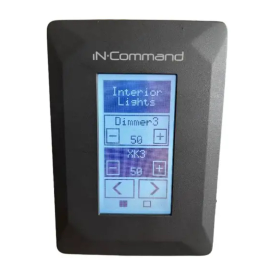
- Page 3 • Tools and Supplies • Safety Passcode Lock Screen for motorized functions You will need these tools and supplies to install your NCSTS9: • Passcode Lock Screen OFF behavior to sync with DC setting • 1.0 mm flat head screwdriver •...
-
Page 4: Installation
NCSTS9 • Mounting the Touch Switch Panel Up to 8 Touch Switches can be added to a single floor plan. To add multiple Touch Switches, adjust the DIP switch on • Cut/Drill hole, allowing space below for future programming and the back accordingly. - Page 5 NCSTS9 2. Connect Power and RV-C cables to the NCSTS9. 3. Use screws to attach the NCSTS9 to the wall. Reattach the Front cover by placing it over the upper four clips and push it into place until it clicks.
- Page 6 NCSTS9 • Loading the Floor Plan The floor plan for the NCSTS9 gets loaded through the NCSP3/35 3. In the software page, you can choose to update the Floor Plan. Display Commander. 1. Select “Settings”. 4. Press load next to the floor plan created for the Display Commander and NCSTS9.
-
Page 7: Fcc Notes
NCSTS9 • FCC NOTES 5. Press Dismiss to finish upload. WARNING! Changes or modifications to this unit not expressly approved by the party responsible for compliance could void the user’s authority to operate the equipment. NOTE: This equipment has been tested and found to comply with the limits for a Class B digital device, pursuant to Part 15 of the FCC Rules. - Page 8 Features and specifications subject to change without notice. 1-877-305-0445 For further technical support call: MA-1709002-1R...