Table of Contents
Troubleshooting

Related Manuals for UTC Fire and Security Chubb VS-MKII

Summary of Contents for UTC Fire and Security Chubb VS-MKII
- Page 1 Installation, Operation and Maintenance Manual © Chubb Fire Safety 2010 Company Confidential...
-
Page 2: Publication Information
VS-MKII Control System Publication Information Development Craig Hafey Technical Manager - Vehicle Fire Suppression Chubb Fire & Security Pty Ltd 149-155 Milton St Ashfield NSW 1800 Tel: +61 (2) 9581-6364 Email: Craig.Hafey@chubb.com.au Publication: Version: Version 1.1 Date: 10-09-12 Title: VS-MKII Control System – Installation, Operation and Maintenance Manual ©... -
Page 3: Pre-Face
VS-MKII Control System Pre-Face Document History: Version Summary of Change Original Page 3 - Changed contact number Page 8 - Primary power monitoring - changed “<20 Volts” to “<17 Volts” Page 11 - Updated figure 9 Page 13 - Updated tables 2 & 3 Page 24 –... -
Page 4: Table Of Contents
VS-MKII Control System General Information Contents: Publication Information ........................2 Pre-Face ............................3 General Information ........................4 Topic 1: VS-MKII Control System ....................6 Introduction ..........................6 Standard features ........................7 Models ............................7 Power Supply ..........................8 Primary power monitoring Rechargeable back up battery Topic 2: Installation ........................ - Page 5 VS-MKII Control System About this manual: This manual is written for those who perform tasks associated with the installation, operation and maintenance of the VS-MKII Control System. Chubb Fire & Security Pty Ltd (“Chubb”) assumes no responsibility for the application of any systems other than those addressed in this manual.
-
Page 6: Topic 1: Vs-Mkii Control System
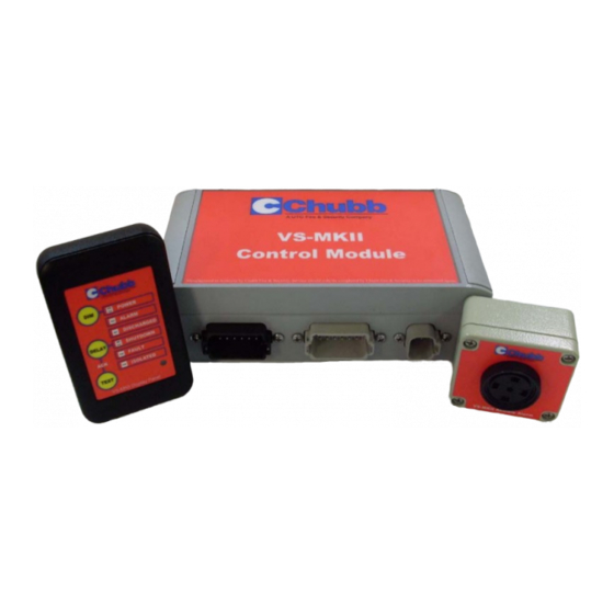
VS-MKII Control System Topic 1: VS-MKII Control System Introduction Designed to comply with and tested to the requirements AS 5062, the VS-MKII Control System (“MKII”) comprises a control module, a remote display panel and audible alarm unit. The display panel provides visual indication of system status, alarms, and faults and also allows manual extension of the equipment shutdown delay. -
Page 7: Standard Features
VS-MKII Control System Standard features • • IP 65 rated control box Variable engine shutdown delay periods 0 - 240 seconds • • Cylinder low pressure switch input Variable shutdown delay extension period 0 - 240 seconds • • Discharge pressure switch input Slimline operator display •... -
Page 8: Power Supply
VS-MKII Control System Power Supply The MKII operates on a 24 Volt primary power supply (20-30 Volt range). If the system is installed in equipment that uses a 12 Volt power supply, a separate voltage converter will need to be installed to boost the voltage. -
Page 9: Rechargeable Back Up Battery
VS-MKII Control System When the panel receives > 31 volts for a period in excess of 10 seconds the amber ‘POWER’ LED • will light up (Fig. 6) but no audible or visual fault will be generated. In this state, the batteries will not be under charge. -
Page 10: Topic 2: Installation
VS-MKII Control System Topic 2: Installation Depending on the type and size of equipment requiring protection, the MKII can be configured with multiple actuation and detection devices. Figure 8 – Typical fire system configuration The MKII can be customised to suit just about any application. The settings that can be altered and the degree to which they can be customised are detailed in the ‘Channels’... -
Page 11: Control Module
VS-MKII Control System Control Module The control module (Fig. 4) comprises an IP65 rated enclosure and IP69 rated Deutsch DT series connectors and is the heart of the system. It can be installed with the factory (“default”) settings or configured to suit a specific requirement. -
Page 12: Configuring The Module
VS-MKII Control System Configuring the module It is recommended that any configuration changes that are required to the default settings be carried out before installation. It is preferable to use an external power supply to make configuration changes. When a stable primary power supply is present the ‘PRIMARY POWER OK”... -
Page 13: Channels
VS-MKII Control System LED’s The user interface is surrounded by a thick white border and the controls and indicators consist of; • A push button labelled ‘Channel’. • A push button labelled ‘PROG/SAVE’. 7-Segment • A 7-segment display. display • 8 LED indicators numbered 1 to 8 from left to right. -
Page 14: Programming - Configuration Channels
VS-MKII Control System Programming - configuration channels If the factory default settings are acceptable, no additional programming is required to the MKII before installation. If a new configuration is required your will need to re-program the system. It is recommended that a stable and constant power supply be present when programming the MKII. - Page 15 VS-MKII Control System Step 2 - Pre-programming When the desired channel is selected, change the dip switch positions using a flat bladed screwdriver (Fig. 20) to mirror the illuminated LED’s. (On LED = On switch.) some channels have configurations more then function, failure to perform this step may result in a undesirable configuration...
- Page 16 VS-MKII Control System Step 5 - Saving changes After you have set the dipswitches to the desired positions, press and hold the “PROG/SAVE” button for 3 seconds to save the new configuration (Fig. 25). The system will now generate a fault which is designed to prompt a user to perform the next step.
-
Page 17: Configuration Channels (A-Y)
VS-MKII Control System Configuration channels (A-Y) A. Inputs and Outputs 1. The manual actuation input can be disabled when not in use. The equipment shutdown output can be disabled when not in use. Upon alarm, the alarm indicator on the Display will be activated and the buzzer output will start to sound once every second but the shutdown sequence will not start and the shutdown indicators will remain in inactive state. - Page 18 VS-MKII Control System 2. Single & Isolate Mode – As per single mode but detection circuit 2 is enabled to allow interface with an external switch that would be fitted for the purpose of isolating the MKII, thus preventing electrical actuation during routine maintenance on the equipment. Figure 29 –...
- Page 19 VS-MKII Control System Description - Auxiliary Mode The MKII incorporates an auxiliary output ‘AUX’ that can be interfaced with the engine management system of a third party device to signal one of the following events; 1. Alarm 2. System Fault 3.
- Page 20 VS-MKII Control System C. Shutdown delays Shutdown Delay – Initial The default setting for the shutdown delay (the time it takes for the shutdown relay to operate after a fire alarm) is 30 secs. Shutdown delay times can be chosen in 5 second intervals from 0 to 20 seconds, 10 second intervals from 20 to 40 seconds, 20 second intervals from 40 to 180 seconds and 30 second intervals from 180 to 240 seconds.
- Page 21 VS-MKII Control System d. Discharge delays Immediate discharge gives the suppression system the best chance of suppressing the fire in its early stages; however, in special circumstances delaying the discharge of the suppression system may be desirable. To cater for such circumstances, (such as operator safety) a discharge delay timer is provided with selectable delay periods - see Table 7.
- Page 22 VS-MKII Control System Switch No. Time Channel Actuation 2 (Seconds) Actuation 1 Discharge Delay Discharge Delay MKII Dual only 0 (Default) Table 7 – Actuation time delays E. Battery test An automated battery test is conducted automatically by the MKII software on the 15th day of every month at 9am.The test is necessary to ensure that battery integrity is maintained.
- Page 23 VS-MKII Control System Rescheduling of battery test shall continue indefinitely until it has successfully started a test and then it shall resume the normal test cycle (15th day of every month). The battery test will also terminate pre-maturely if any of the following events occurred during the test period, •...
- Page 24 VS-MKII Control System F. Input polarity Each input (device) connected to the MKII uses a pair of contacts that are either ‘normally closed’ (N/C) to allow current to flow from one contact to the other, or, ‘normally open’ (N/O) to prevent current from flowing.
- Page 25 VS-MKII Control System U. Open circuit supervision All of the inputs and outputs can be enabled or disabled for open circuit supervision. The default settings will not normally need to be changed. Channel Switch No. State Function ON (Default) Manual Discharge – Enable O/C supervision Manual Discharge –...
- Page 26 VS-MKII Control System Real Time Clock The MKII incorporates an Event Logger and Real Time Clock (RTC) which allows up to 80 faults, alarm, shutdown, isolation and other maintenance events to be date and time stamped and stored in system non-volatile memory for later retrieval and analysis. The RTC is kept by an onboard battery (Fig.
- Page 27 VS-MKII Control System n. Acknowledge feature settings An event acknowledgement function is provided on the MKII keypad using a combination button press (Fig. 35). Once an event is acknowledged, the audible alarm unit will be silenced for the configured time period. Pressing the “DELAY”...
- Page 28 VS-MKII Control System P. Configuration preset Channel ‘P’ allows a user to reset all of the configurations back to the default (factory) settings. Changing the configuration preset can only be performed while the system is isolated to ensure that there is an additional level of protection against unintentional changes and to also prevent the system from discharging on reset.
-
Page 29: Jumper Links
VS-MKII Control System Jumper links The MKII module PCB is installed with two jumper links. One link is used to isolate the MKII for maintenance purposes and the other to change contacts on the auxiliary output. 1. Maintenance Isolate 2. Auxiliary output ontacts Figure 36 - Module PCB Jumper links 1. -
Page 30: Shutdown Bypass
VS-MKII Control System Shutdown bypass This button returns the shutdown relay output to normal condition. This is to allow temporary movement of equipment after an alarm for safety or maintenance purposes. Shutdown bypass Figure 37 – Module PCB Shutdown bypass To initiate, press and hold the button for once (1) second. -
Page 31: Installing The Mkii Module
VS-MKII Control System Installing the MKII Module Mount the MKII control module at a suitable location in the equipment away from the fire hazard area. For wiring purposes the preferred location is within the equipments cabin. • The module can be secured on any surface of the equipment using the four mounting holes and the bolts supplied. - Page 32 VS-MKII Control System The PCB on the display panel also has a system reset button as indicated in Figure 39. 2. Dip switches 1. System reset Figure 41 - Display PCB The eight (8) DIP switches in Table 25 are used to operate the following functions: 1.
-
Page 33: Display Controls And Indicators
VS-MKII Control System 2. Maintenance isolate This switch performs the same function as the “Isolate” link of the MKII module. The switch isolates the actuation, auxiliary alarm and shutdown outputs from the control module and illuminates the ISOLATED LED on the display and the audible alarm unit will beep once per minute. All inputs remain enabled along with the audible alarm unit output, fault output and display panel LED’s. -
Page 34: Audible Alarm
VS-MKII Control System Audible Alarm The audible alarm unit (Fig. 43) is IP65 rated enclosure, supplied with a 6 metre long cable and 4 x M4x25mm Stainless Steel Bolts and nuts. Figure 43 - Audible alarm unit If required, it is possible to connect up to five (5) alarm units in parallel. When installing multiple alarm units, switch ‘1’... - Page 35 VS-MKII Control System Connecting the display panel to the control module Figure 48 - Display wiring Connecting the buzzer to the control module Figure 49 - Audible alarm wiring Chubb Fire & Security Pty Ltd Technical Manual Page 35 of 63...
-
Page 36: Electrical Manual Release Unit
VS-MKII Control System Electrical Manual Release Unit The manual release unit consists of an IP65 rated metal enclosure with a glanded cable entry. A M18 cable gland and two bolts are also provided with each unit. It incorporates a switch fitted with a series and a parallel EOL resistor to allow it to be monitored for both open and short circuit faults. -
Page 37: Operation
VS-MKII Control System Operation When activated, the switch will change the circuit resistance (to approx 33 ohms) so that the panel can no longer see the EOL resistor (1000 ohms). The panel will interpret this new resistance as an Alarm condition. If the circuit is disconnected or shorted, the panel will interpret no resistance as a Fault condition in this circuit. -
Page 38: Installation - Multiple Units
VS-MKII Control System Step 5. Thread the cable through the gland and check that length and flexibility of the wires. Step 6. Connect the wires to the terminal block. A slight tug on the cable will confirm that the wires are securely clamped. - Page 39 VS-MKII Control System Step 3. Remove safety pin and loosen lock nut. Rotate switch assembly so that the circuit card is accessible. Remove resistor (R1) on each unit before the last. The last unit’s resistor remains to act as the EOL. Step 4.
-
Page 40: Solenoids
VS-MKII Control System Connecting manual electric actuator to the control module Figure 52 - Electrical actuator wiring Solenoids Electric actuation of both ROP and LOP PEFS systems is achieved using a 12V DC10W solenoid operated valve. Terminals 1 and 2 of the solenoid coil are used to connect it to the MKII. The earth terminal of the coil is not used. -
Page 41: Installing A Solenoid
VS-MKII Control System Installing a solenoid Step 1. Strip the outer cable sheath to expose wires and pass the cable (7) through the gland (4), washer (5), rubber seal (6), housing (2) in this order and connect to terminal block (3) to the housing (2). -
Page 42: Linear Heat Detection Cable (Lhd)
VS-MKII Control System Linear Heat Detection Cable (LHD) LHD cable consists of two insulated conductors (black and black with white stripes) twisted together and sheathed in a red PVC casing and senses a fire when heated to a temperature between 168 C and 180 anywhere along its length. - Page 43 VS-MKII Control System Step 3. Refit brass cover and tighten the gland until cable is sealed. Step 4. Use jiffy splice or Deutsch cable connectors to connect the LHD cable to field wiring back to the VS-MKII control module. Deutsch connectors should always be used where a break away connection is required.
-
Page 44: Pressure Switches
VS-MKII Control System Pressure switches Two pressure switches inputs are available for use in the VS-MKII Control system: The two pressure switches that are being used in the PEFS system are; 1. “Pressure Low”, 1,200kPa setting (part number 87042) 2. “Discharge”, 200kPa setting (part number 87041) Both switches have a 1/8”NPT connection, are configurable for NO or NC, and are provided with a IP65 rated Deutsch DTM series connector. -
Page 45: Multiple Pefs Cylinder Installations
VS-MKII Control System Multiple PEFS Cylinder Installations Pressure Low switch For multiple LOP cylinder installations, which have a common LOP actuation system, a single cylinder low pressure switch may be fitted either to: • one of the cylinder valves’ low pressure switch ports •... - Page 46 VS-MKII Control System Connecting multiple PEFS pressure switches to the control module. Multiple switches must always be installed in series (Fig. 63). Figure 63 - PEFS multiple cylinder pressure switch wiring Notes: Chubb Fire & Security Pty Ltd Technical Manual Page 46 of 63...
-
Page 47: Topic 3: Commissioning
VS-MKII Control System Topic 3: Commissioning The VS-MKII Control System can be installed as a stand alone detection system but will more than likely be installed as part of a fire suppression system. Regardless of the configuration or complexity of the fire system, a full commissioning test must be completed prior to placing the system in service to ensure that the system is installed correctly, meets design specifications and is fully functional. -
Page 48: Topic 4: Troubleshooting
VS-MKII Control System Topic 4: Troubleshooting Audible and visual fault indications, consisting of illumination of the MKII display’s Fault LED and sounding of the buzzer once every 10 seconds, will be generated when the system detects an abnormal condition or a defect, which may impair the efficiency of the system, or potentially lead to a failure. -
Page 49: Control Module - Fault Indications
VS-MKII Control System If ‘Other’ is being indicated by the display the user interface on the control module will need used to find the cause of the fault. Control module – Fault Indications Refer to page 13, ‘Programming - configuration channels’, ‘Using the interface’... - Page 50 VS-MKII Control System 3. System faults 3 Channel LED No. Fault History Log Disabled – Controller History Log Disabled – Display EEPROM Checksum Error – Controller FLASH Checksum Error – Controller EEPROM Checksum Error – Display FLASH Checksum Error – Display Controller Unit Display Unit Table 32 - System faults 3...
-
Page 51: Replacing The Internal Back Up Battery
VS-MKII Control System 8. Test Channel Channel 8 is the test channel that allows a user to check the LEDS and the segment display for faults. Channel Display Description Any Segments missing on the display will indicate a display hardware fault that will require repair at the factory. - Page 52 VS-MKII Control System Step 3. Turn the card over and locate the battery connector. Step. 6 Pinch the connector to disengage locking mechanism and remove. Step 7. Remove the old battery pack and fit the new battery using the adhesive tape provided. Note: Check the voltage in the new pack with a multimeter before fitting.
-
Page 53: Troubleshooting With Terminal Software
VS-MKII Control System Troubleshooting with Terminal software The VS-MKII control module includes an RS232 connection to allow interrogation and download of system status and event history. Firmware updates can also be uploaded using the RS232 connection. A cable (part number 87012) to connect to a laptop computer is required for this purpose. The software that interfaces with the Module is called “TeraTerm4”. - Page 54 VS-MKII Control System Step 3. Open the ‘TeraTerm’ folder by double clicking on the icon to reveal the directory structure contained within Figure 70 - TeraTerm folder Step 4. Open the terminal software by double clicking on the “ttempro.exe” icon. Figure 71 - ttermpro.exe Chubb Fire &...
- Page 55 VS-MKII Control System When the program starts it will automatically start searching for the VS-MKII control module (device). Figure 72 - Searching for device A status window will pop up when a successful connection has been made. The command prompt will also appear ‘Cmd>>’.
-
Page 56: Teraterm Commands
VS-MKII Control System If you receive the message show in Figure 69 then you may need to re-install the driver of any USB to RS232 connector or change your Window’s port settings. For further assistance contact the Chubb Helpdesk or Tech Services in Silverwater to resolve. Figure 74 - No device If the terminal window doesn't maximise correctly to your screen, left click on the blue menu bar and hold whilst moving the window to the right. - Page 57 VS-MKII Control System F11 - Set time and Date A RTC fault occurs when the system detects an incorrect date setting. This could indicate that the time and date has not been set correctly or that the RTC battery (small battery on the VS-MKII control module PCB) is faulty.
- Page 58 VS-MKII Control System Chubb Fire & Security Pty Ltd Technical Manual Page 58 of 63...
- Page 59 VS-MKII Control System Understanding log events The events recorded in the history log are the most useful in troubleshooting faults. In TeraTerm the event log will be displayed in the format displayed in Table 38. Event Type Board Address Condition Status Value Time...
-
Page 60: Troubleshooting Tables
VS-MKII Control System Troubleshooting Tables Failure of the VS-MKII Control system to function properly will usually be caused by one or more of the following faults: 1. Failure of the Power Supply 2. Incorrect Installation 3. Damaged Wiring or Corrosion 4. -
Page 61: Other Fault Indicators
VS-MKII Control System Other fault indicators If there are no power or alarm problems and the system is still in fault, run the fault analysis on the display or the control module to determine which condition(s) exist and perform the suggested corrective action. Probable Causes Fault Corrective Action... -
Page 62: Hardware Problems
VS-MKII Control System Probable Causes Fault Corrective Action History log on one Check display and module. Re-enable History log disabled of the units has logging been disabled. Unrecoverable Controller unit fault Replace module errors. Unrecoverable Display unit fault Replace display errors. -
Page 63: Feedback Form
VS-MKII Control System Feedback Form We welcome feed back regarding this manual. If you have any recommendations for improvement please provide details using this form. Fax to: Craig Hafey, +61 (0)2 8748 7450 Email: Craig.Hafey@chubb.com.au 1. PART NUMBER 2. TITLE: 3.
Need help?
Do you have a question about the Chubb VS-MKII and is the answer not in the manual?
Questions and answers