Table of Contents
Advertisement
Quick Links
Advertisement
Table of Contents

Summary of Contents for GFS Deluxe
- Page 1 Deluxe Control Panel Operator Manual Document Number: 1056655 rev 0 Publication date 12/02/2021 Read and keep this manual for future reference. All personnel operating the equipment described in this manual should review and understand all instructions before use.
-
Page 2: Table Of Contents
Safety notices ......................... 4 Information notices ......................... 4 General safety ............................5 Product safety ............................7 Deluxe control panel ..........................8 Operating modes and controls ......................... 9 Optional equipment setup ........................11 Common device setup ........................11 If applicable: Manual balance setup ..................11 If applicable: Consta-Flow setup .................... -
Page 3: Introduction
By combining high-quality components, strong relationships with paint manufacturers, and our experienced distribution network, GFS provides the best equipment and support to set your business up for success. -
Page 4: Conventions Used In This Manual
Introduction Conventions used in this manual This section describes how information is presented, organized, and referenced within this manual. Safety notices This manual uses the following standards to identify conditions related to safety hazards and equipment damage. Table 1. Safety notices Symbol Description Indicates an imminent hazard that will result in death. -
Page 5: General Safety
WARNING The roofs of GFS equipment are not designed or intended to be walked upon or to support weight of any kind. As designed and manufactured, equipment roofs do not meet the minimum requirements of a safe walking and/or working surface under OSHA 1910.22. - Page 6 Operate this equipment in accordance with the guidelines set forth in this manual. It is impossible to list all potential hazards of this equipment. Instruct all personnel involved with this equipment in the safe conduct and operation of the system. GFS recommends that only qualified personnel operate and maintain this equipment.
-
Page 7: Product Safety
Product safety Product safety For product safety information, refer to the documentation that accompanied your equipment. Global Finishing Solutions 1056655 rev 0... -
Page 8: Deluxe Control Panel
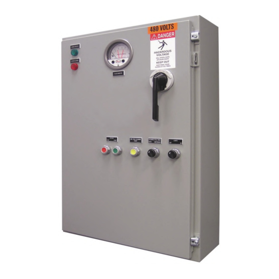
NOTE The Deluxe control panel is available for single or three phase power circuits and all standard North American voltages. Custom voltages are available. The control panel is mounted on the outside of the booth or on a nearby wall in a convenient position for the operator. -
Page 9: Operating Modes And Controls
Operating modes and controls Operating modes and controls The front of the Deluxe control panel provides the following controls and indicator lights: NOTE Some of these controls are optional and may not be present on every control panel. Table 3. Spray booth operating states and controls... - Page 10 Operating modes and controls Displayed Text Description Intake Unit On Indicates that the intake fan is operating when lit. Fire System Fault Indicates a fire protection system fault or alarm when lit. Keypad with Dial Used to set the airflow in booths with manual balance. Airflow Controller Pressure gauge with setpoint needles used for setting airflow in booths with Consta- Flow systems.
-
Page 11: Optional Equipment Setup
A velometer is required to test the airflow and properly set up manual balance. Deluxe control panels equipped with optional manual balance systems have a keypad with a dial that controls the variable frequency drive (VFD). You can use the keypad and dial to manually increase the fan frequency as the filters load. -
Page 12: If Applicable: Consta-Flow Setup
• During setup, perform measurements in an empty booth. NOTE A velometer is required to test the airflow and properly set up Consta-Flow. Deluxe control panels equipped with optional Consta-Flow systems automatically adjust the fan speed and maintain consistent airflow throughout the life of the filter. NOTE Consta-Flow systems may be configured with either a sensor installed in the exhaust stack on site or with a flow ring built into the exhaust fan. - Page 13 Optional equipment setup A: Low-pressure bulkhead fitting B: High-pressure bulkhead fitting C: Low-pressure sensing tube D: High-pressure sensing tube E: Exhaust stack F: Consta-Flow sensor G: Control panel H: Outside booth (minimum 3 feet from any opening) Figure 3. Consta-Flow sensor Global Finishing Solutions 1056655 rev 0...
- Page 14 Optional equipment setup A: Low-pressure bulkhead fitting B: High-pressure bulkhead fitting C: Exhaust fan D: Motor E: Flow ring (Sure-Aire or Piezometer) F: Exhaust stack G: Control panel H: Outside booth (minimum 3 feet from any opening) Figure 4. Consta-Flow flow ring Perform the steps below to configure the Consta-Flow airflow controller (Photohelic): With the booth off, ensure that the black indicator needle on the Photohelic is set to zero.
- Page 15 Optional equipment setup Using the provided tool, twist the knobs on either side of the Photohelic so that the left-most orange needle is positioned all the way to the left and the right-most orange needle is positioned all the way to the right.
-
Page 16: Device Setup For Spray Booths
NOTE A velometer is required to test and properly set up intake airflow. Deluxe control panels equipped with optional Auto Balance systems automatically adjust the fan speed and maintain consistent airflow throughout the life of the filter. Global Finishing Solutions... - Page 17 Optional equipment setup NOTE The Auto Balance system should be installed as shown in the Electrical Drawings and in the following diagram. A: High-pressure air-sensing pressure tip (Locate inside the booth a minimum of 84 inches from the floor at at least 24 inches from any corner.) B: High-pressure air-sensing tube C: Low-pressure air-sensing pressure tip (factory installed)
-
Page 18: If Applicable: Air Proving Switch Setup
Optional equipment setup Using the provided tool, twist the knobs on either side of the Photohelic so that the left-most orange needle is positioned at zero and the right-most orange needle is positioned at positive 0.03 inches w.c. Start the booth. Use the velometer to test the booth's airflow. - Page 19 Optional equipment setup The optional air proving switch is part of the booth’s ventilation system and is used to prove airflow across the exhaust fan. Loss of exhaust airflow causes the air solenoid valve to shut off, turning off spray air in the booth.
-
Page 20: If Applicable: Dirty Filter Alert Setup
Optional equipment setup If applicable: Dirty filter alert setup Scope: This task applies only to spray booths if the site purchased the optional dirty filter alert. Prerequisites: • The air solenoid valve must already be installed. • Filters must be installed in the booth. The optional dirty filter alert will sense the differential pressure across the exhaust filters. -
Page 21: Device Setup For Powder And Dust Booths
Optional equipment setup For each 0.1 inch w.c., turn the adjustment screw a half turn clockwise. For example, a final filter pressure of 1/2-inch w.c. requires an additional five half turns clockwise. Start the ventilation system and note the differential pressure shown on the manometer or similar device. - Page 22 Optional equipment setup Figure 8. Pulse control board NOTE Initial parameters for the pulse control board are configured prior to product shipment. Refer to settings in the Electrical Drawings for more information. If the filters are continuously pulsing and not achieving the low limit, the high and low limit ranges must be increased.
-
Page 23: If Applicable: Redundant Filter Alert Setup
Optional equipment setup With the booth off, ensure that the black indicator needle on the Photohelic is set to zero. To adjust the indicator needle, use a small screwdriver to turn the zero adjustment screw. Using the provided tool, twist the knobs on either side of the Photohelic so that the left-most orange needle is positioned at 2 inches w.c. - Page 24 Optional equipment setup Figure 9. Differential pressure switch Perform the steps below to configure the redundant filter alert: Ensure that the ventilation system is in operation. Remove the cover from the differential pressure switch and locate the adjustment screw. Carefully turn the screw until it is fully counterclockwise.
-
Page 25: Using The Spray Booth
Using the spray booth Using the spray booth This section describes how to operate a spray booth that has a Deluxe control panel. Starting the booth Perform the following steps to apply power to the booth: If required: Turn on booth power at the Main Power Disconnect. -
Page 26: Shutting Down The Booth
Using the spray booth A timer in the control panel must be configured before Economy mode is activated. Set the desired time by rotating the dial so that the red indicator needle is at the desired time setting.The dial is configurable in minutes or seconds with a numerical time range of zero through ten. -
Page 27: Using The Dust Or Powder Booth
Auto cleaning Automatic Cleaning (set on the selector switch at the front of the Deluxe control panel), pulses filters with compressed air when the pressure drop is within the set range when the pressure drop reaches the high limit setpoint. -
Page 28: Redundant Filter Monitoring
Using the dust or powder booth Redundant filter monitoring Monitors the pressure drop across the redundant filters. If these filters become loaded, the Filter Fault indicator lights and the booth subsequently shuts down. See “Troubleshooting” (page 29) for more information. Shutting down the booth Perform the following steps to shut down the booth: Press the red System Stop pushbutton at the front of the control panel. -
Page 29: Troubleshooting
Troubleshooting Troubleshooting WARNING Some of the troubleshooting procedures may require access to live circuitry. Dangerous accidental contact with line voltage may be possible. Only qualified service personnel should perform these procedures. NOTE If fault and warning codes recur after troubleshooting or you need additional assistance, contact Global Finishing Solutions at 800-848-8738 to speak to a Technical Service Representative. - Page 30 Troubleshooting Symptom Probable Cause Remedy Motor starter tripped 1. Reset the motor start overload. 2. Verify all motor wiring is correct, in good condition, and terminal connections are tight. 3. Check fan and motor condition. Table 6. Troubleshooting powder and dust booth issues Symptom Probable Cause Remedy...
Need help?
Do you have a question about the Deluxe and is the answer not in the manual?
Questions and answers