Table of Contents
Advertisement
Quick Links
Advertisement
Table of Contents

Summary of Contents for Gunnebo Wedge K12
- Page 1 Operation and Maintenance Instructions Wedge K12...
-
Page 2: Table Of Contents
Table of Contents OPERATION ......................... 3 OPERATION DURING POWER FAILURE ................4 2.1. S ..................4 YSTEM WITHOUT CCUMULATOR 2.2. S ....................4 YSTEM WITH CCUMULATOR CONTROL UNIT AND ELECTRICAL FUNCTION ..............5 3.1. G ..........................5 ENERAL 3.2. O ................ -
Page 3: Operation
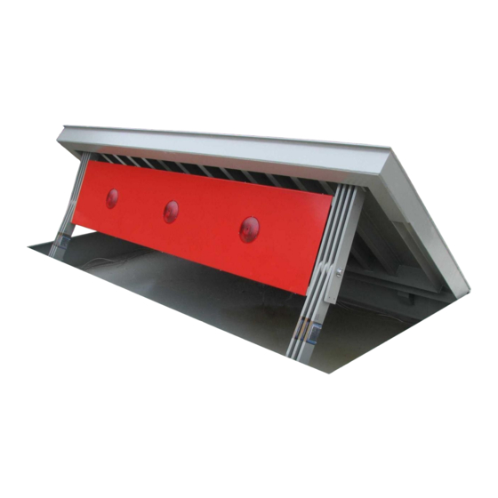
Every movement of the system’s blocking element must be carefully monitored. (3) The tolerable impact load of the WEDGE K12 amounts to 1852 kJ. This is equivalent to the impact force of an approx. 7.5 ton heavy vehicle with an initial speed of 80 km/h. -
Page 4: Operation During Power Failure
Operation during Power Failure Raise the blocking element 1. Operate the Wedge using the hand pump (6) until the fully raised position is reached. Lower the blocking element 1. Operate the Wedge using the ball cock (5) until the fully lowered position is reached. 2.1. -
Page 5: Control Unit And Electrical Function
Control unit and electrical function 3.1. General The control unit processes signals coming from outside via terminal strips. It controls the commands for operation of the wedge, operates the solenoid valves of the hydraulic unit and offers a variety of indications and control elements. 3.2. - Page 6 Automatic on / off In „automatic“-mode the Wedge barrier moves automatically into the blocking position after expiration of the time pre-set T10, provided that the light barriers are not interrupted and the induction loops are not occupied. The function of control switches “lower”, “stop”, “raise”, induction loops and light barriers is always independent of the automatic function.
-
Page 7: Outputs
3.2.2. Outputs Hydraulic motor The hydraulic engine runs only during the raising operation of the Wedge (Standard). If the hydraulic drive unit is equipped with an accumulator (optional) the engine may running also to refill the accumulator. This process is activated by a pressure watcher and is not depending on the operation of the Wedge. -
Page 8: Change Of Time Parameters At The Control Unit "Easy
3.3. Change of time parameters at the control unit “Easy” The control is switched on and the word “run” will appear on the bottom at the right hand side of the display. With the ok key you enter the main menu. Here you can confirm the menu option parameter selection (parameter flashes) by using the arrow keys up/down and the ok key. -
Page 9: Maintenance
Maintenance The maintenance work may only be carried out by qualified persons. The maintenance work consists of: General visual examination Examination of screws Examination of electrical and hydraulic connections Changing of the hydraulic oil Cleaning Attention! Before maintenance work can begin the main switch for the power supply must be switched off and secured against inadvertent activation of the switch. -
Page 10: Hydraulic Drive Unit And Hydraulic Components
4.1.2. Hydraulic Drive Unit and hydraulic components (1) Press the selector switch “Flush” (Option) located in the control cabinet for at least 60 sec. (2) Check for damage to the hydraulic lines. (3) Check the hydraulic cylinder (hydraulic cylinders) (5) and all hydraulic screw connections for oil leaks (tighten if necessary). -
Page 11: Major Maintenance
4.3. Major Maintenance Major Maintenance should be carried out after 1,000 operational hours or at the very latest every 2 years. This includes all work described in the monthly maintenance (see section 3.1). In addition to this the following tasks are required: (1) Examination of all functional parts, connections and screw connections for their intactness and tight fit. -
Page 12: Trouble-Shooting
Trouble-Shooting A malfunction which can cause the blocking element not to move can have several different causes. The most frequent causes and their remedies are listed below. — Cause: power is interrupted. Remedy: check the electrical lines of the current entry. With power failure implement hand operation (see section 2).


Need help?
Do you have a question about the Wedge K12 and is the answer not in the manual?
Questions and answers