Table of Contents
Advertisement
Quick Links
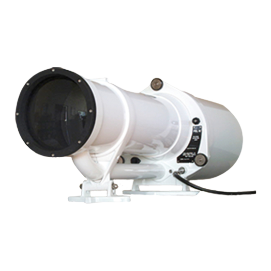
PEL 6 Marine Sector Light
Installation and Instruction Manual
Available colour range
Subtense
This manual applies from serial #:
Calc version:
Manual version:
Date released:
Status:
V E G A I N D U S T R I E S L I M I T E D
PEL-6 Sector Light Product Manual
Red, White, Green
3.5°, 5.0°, 7.5°, 10°, 15°, 20°
Calc2001
1.1.1
21 October 2008
Released by IG
Advertisement
Table of Contents

Summary of Contents for Vega Industries PEl 6
- Page 1 V E G A I N D U S T R I E S L I M I T E D PEL 6 Marine Sector Light Installation and Instruction Manual PEL-6 Sector Light Product Manual Available colour range Red, White, Green Subtense 3.5°, 5.0°, 7.5°, 10°, 15°, 20°...
- Page 2 Installation and Operation Manual PEL - 6 © Vega Industries Ltd, April 2008 Manual quick reference Description of Change Date manual released Manual version Software version PEL Serial number Re-issue of manual April - 08 Calc2001 -updated formatting Warranty clause added October 2008 1.1.1...
-
Page 3: Table Of Contents
Installation and Operation Manual PEL - 6 © Vega Industries Ltd, April 2008 1.0 General Description.......................... 4 Introduction......................... 4 Lamps Used in PEL Sector Lights..................4 1.21 Power Supplies for PEL Sector Lights ................5 Colour Filter Assembly....................... 5 Intensity Reduction Filter .................... -
Page 4: General Description
Installation and Operation Manual PEL - 6 © Vega Industries Ltd, April 2008 1.0 General Description. Introduction The standard light source of the PEL Sector Light is the 250 watt long-life Thorn M36 tungsten-halogen (TH) lamp. A highly efficient and patented optical condenser system collects most of the available light energy into an intense beam which is emitted through a precision projection system. -
Page 5: Power Supplies For Pel Sector Lights
Installation and Operation Manual PEL - 6 © Vega Industries Ltd, April 2008 collets every time lamps are replaced. Ensure the pin size of the lamp is Ø1.25mm 1.21 Power Supplies for PEL Sector Lights There is a potential problem when using power supplies with a high internal inductance to drive low-voltage lighted navigation aids. -
Page 6: Intensity Reduction Filter
Installation and Operation Manual PEL - 6 © Vega Industries Ltd, April 2008 Intensity Reduction Filter This is a neutral density filter which is mechanically inserted into the beam to reduce the intensity of the emitted light for night operations. -
Page 7: Projection System
Installation and Operation Manual PEL - 6 © Vega Industries Ltd, April 2008 Projection System The sharp boundaries of the PEL Sector Light are produced by a two-component positive projection lens in models with a subtense greater than 10° and a singlet projection lens in the case of the 5°... -
Page 8: Mounting And Installation
Installation and Operation Manual PEL - 6 © Vega Industries Ltd, April 2008 2.0 Mounting and Installation Acceptance Inspection Before connecting the sector light to any power supply, the following steps should be carried out: 2.1.1 After removing the unit from the packing case, an inspection should be carried out to check that no damage has occurred during transit. -
Page 9: Alignment Of Sector Light
Installation and Operation Manual PEL - 6 © Vega Industries Ltd, April 2008 Alignment of Sector Light 2.4.1 Adjust the angle of elevation of the beam so that the vertical centre is at the average height of a ship’s bridge at the maximum range at which the light is used. Align the sector pattern in azimuth using an observer located on the boundary between two adjacent sectors. -
Page 10: Masking Stray Light
Installation and Operation Manual PEL - 6 © Vega Industries Ltd, April 2008 Masking Stray Light 2.5.1 In an optical projection system at least 0.5% of the light will be scattered by the last lens surface, and even more if the lens is not completely clean. In the case of a very powerful sector light there can be enough stray light for an observer outside the beam to think he or she is inside the beam. -
Page 11: Calc (Electronic Controller) Connections
Installation and Operation Manual PEL - 6 © Vega Industries Ltd, April 2008 CALC (Electronic Controller) Connections 3.2.1 The CALC-2001 unit electronically controls all the functions performed by the Sector Light. This includes intensity changes for day/night operation, the imposition of flash characters if required, and drives for stepping motors. -
Page 12: Lampchanger Operation
Installation and Operation Manual PEL - 6 © Vega Industries Ltd, April 2008 4.0 Lampchanger Operation A special Vega Lampchanger is required for the PEL Sector Light to carry the high currents drawn by the lamps, to provide the special collet-mounting system, and to fit within the tight confines of the optical condenser system. -
Page 13: Lamp Alignment On Lampchanger
Installation and Operation Manual PEL - 6 © Vega Industries Ltd, April 2008 Lamp Alignment on Lampchanger 4.2.1 Each TH lamp must be correctly aligned in the lampchanger during fitting. Note that TH lamps are not to be handled with the fingers. This shortens the lamp life considerably, as oils on the fingers react with the quartz material of the lamp envelope. - Page 14 Installation and Operation Manual PEL - 6 © Vega Industries Ltd, April 2008 distorted by irregular lamp envelope contours, but views from each side permit accurate positioning. 4.3.4 The lampchanger base is held down by two 4mm laterally located fixing screws, C and D.
- Page 15 Installation and Operation Manual PEL - 6 © Vega Industries Ltd, April 2008 4.3.8 Have the hold-down screws entered into the lampchanger shelf threads but free to permit the base to be raised to the correct height and tilted laterally and fore- and-aft.
- Page 16 Installation and Operation Manual PEL - 6 © Vega Industries Ltd, April 2008 5.0 Intensity Reduction Mechanism 5.1 General Description The out-put intensity of the PEL-6 Sector Light is controlled automatically for day and night requirements. A Light Dependent Resistor (LDR) senses the light level in order to drive a relay which in turn sets the direction of a stepper motor.
-
Page 17: Parts Listing: Intensity Reduction Filter Assembly
Installation and Operation Manual PEL - 6 © Vega Industries Ltd, April 2008 Parts Listing: Intensity Reduction Filter Assembly 5.3.1 Parts Illustrated in Diagram Key Number Part Number Description 6-289-001 Focusing Ring 6-289-002 Filter Plate Assembly 6-289-003 Pivot Sector Plate... -
Page 18: Oscillating Boundary Device (Optional Extra)
Installation and Operation Manual PEL - 6 © Vega Industries Ltd, April 2008 7.0 Oscillating Boundary Device (optional extra) General Description A filter plate holding the glass filters (typically Red, White and Green) oscillates laterally to produce up to seven separate sectors, three of which are steady colours. In the other four sectors the colour either alternates between the colours in the adjacent sectors, or flashes. -
Page 19: Reassembly Of The Oscillating Boundary Device And Colour Filters
Installation and Operation Manual PEL - 6 © Vega Industries Ltd, April 2008 7.4.4 Unscrew the four 4mm screws holding the condenser assembly and withdraw it off the two locating pins, leaving the 6-plate filter assembly on the pins. 7.4.5 Carefully remove the filter plates, intensity frame and drive-rod as one unit off the locating pins. - Page 20 Installation and Operation Manual PEL - 6 © Vega Industries Ltd, April 2008 freely and generally parallel to the fixed plates. Loosen the suspension strap screws to aid this, and retighten while the plate is held in its proper relationship.
-
Page 21: Exploded View
Installation and Operation Manual PEL - 6 © Vega Industries Ltd, April 2008 Exploded View... -
Page 22: Parts Listing: Intensity Reduction Filter And Oscillating Boundary Device
Installation and Operation Manual PEL - 6 © Vega Industries Ltd, April 2008 Parts Listing: Intensity Reduction Filter and Oscillating Boundary Device Key Number Part Number Description 6-290-001 Focusing Ring 6-290-002 Oscillating Boundary Front Mounting Plate 6-290-003 Oscillating Boundary Spacer... -
Page 23: Maintenance Procedures
Installation and Operation Manual PEL - 6 © Vega Industries Ltd, April 2008 8.0 Maintenance Procedures Objective Lens Clean the external surface of the objective lens at intervals of 90 days. This period may need to be shortened if reduced definition of the sector boundaries or overall intensity reduction is reported. -
Page 24: Seals
Installation and Operation Manual PEL - 6 © Vega Industries Ltd, April 2008 treated with great care. Seals The seal between the rear cover and main frame must be replaced if it becomes hard or perished. It should be lubricated on fitting, and removed and re-lubricated annually.
Need help?
Do you have a question about the PEl 6 and is the answer not in the manual?
Questions and answers