Table of Contents
Advertisement
sales@horstwelding.com · www.hlasnow.com · www.horstwelding.com
Operator's Manual
Keep this manual with the machine at all times
SB3000 SB4000 SB5000 SB6000
Series Snow Blades & EdgeFlex Snow Blades
CAUTION
!
Operational Hazard
Personal Protection Equipment
(PPE) is required when operating
or maintaining this machine.
!
Do not attempt to operate the equipment without thoroughly
Rev 040122
8082 Rd 129 · Listowel · ON N4W 3G8 · Canada
519-291-4162 ·1-866-567-4162 · Fax 1-519-291-5388
see inside manual for full model listing.
SNL00001
reviewing this manual for safe and proper operation.
SB300010
PRINTED IN CANADA
SB600014EF
HS00114 SB3, 4
Advertisement
Table of Contents

Subscribe to Our Youtube Channel
Related Manuals for HLA SNOW SnowBlade SB3000 Series

Summary of Contents for HLA SNOW SnowBlade SB3000 Series
- Page 1 8082 Rd 129 · Listowel · ON N4W 3G8 · Canada 519-291-4162 ·1-866-567-4162 · Fax 1-519-291-5388 sales@horstwelding.com · www.hlasnow.com · www.horstwelding.com Operator’s Manual Keep this manual with the machine at all times SB3000 SB4000 SB5000 SB6000 Series Snow Blades & EdgeFlex Snow Blades see inside manual for full model listing.
-
Page 2: Table Of Contents
Table of Contents Introduction � � � � � � � � � � � � � � � � � � � � � � � � � � � 3 Field Operation � � � � � � � � � � � � � � � � � � � � � � 18 Models . -
Page 3: Introduction
Introduction Thank you for purchasing your new HLA Snow SB series snow blade � Your SB snow blade has been designed and manufactured to give you many years of dependable service. SB Series unique design helps to increase productivity by ensuring safe, effective, and speedy snow plowing at your job site. -
Page 4: General Information
Intended Use The HLA Snow SB3000, SB4000, SB5000 & SB6000 series Snow Blade is intended for attachment and use on qualified power units for the sole purpose of clearing snow. -
Page 5: Safety
Safety This Safety Alert Symbol means: ATTENTION! BECOME ALERT! YOUR SAFETY IS INVOLVED! The Safety Alert symbol identifies important safety messages on the machine and in the manu- al. When you see this symbol, read and understand the message, be alert to the potential hazard in the message. -
Page 6: Accident Prevention
Accident Prevention ACCIDENTS CAN BE PREVENTED WITH YOUR HELP! YOU are responsible for the SAFE operation and maintenance of your machine. YOU must ensure that you and anyone else who is going to use, maintain, or work around the machine be familiar with the work and maintenance procedures and related SAFETY information contained in this manual. -
Page 7: Safety Guidelines
Safety Guidelines Safety of the operator and bystanders is one of the chief concerns in developing and designing equipment. However, every year many accidents occur which could have been avoided by a few seconds of thought and a more cautious approach to handling equipment. -
Page 8: Preparation
Preparation Operation Safety 1. Inspect snow blade for shipping damage. If damage 1. NEVER allow helpers or bystanders under or near the does exist, do not use. Notify your dealer immediately snow blade. to have damaged parts replaced or repaired. 2. -
Page 9: Safe Work
Safe Work Hydraulic Safety Not all work spaces are the same, but the principles 1. Make sure that all the components in the hydraulic presented here can be applied to any work space. system are kept in good condition and are clean. Survey the work site, remove debris and make note of 2. -
Page 10: Safety Labels
Safety Labels Safety labeling is an important part of the overall safe use of the snow blade. Safety labeling alerts and warns against potential injury or death, and is important to follow these points to help keep your snow blade safe for you and others who may be using it. -
Page 11: Safety Label Layout
Safety Label Layout Safety signs and locations on the equipment are shown in the illustrations below. Good safety practice requires that you familiarize yourself with the label and the safety message it is delivering. Be aware of the equipment or particular equipment feature that requires your SAFETY AWARENESS. The SB600012 is shown but the label layout is similar for all SB series snow blades. -
Page 12: Specifications And Dimensions
Specifications and Dimensions Specifications Model SB3000 Series SB4000 Series SB5000 Series SB6000 Series Recommened Power Minimum:2267 kg (5000 lb) Minimum:5897 kg (13000 lb) Minimum:11340 kg (25000 lb) Minimum:18144 kg (40000 lb) Unit Size Maximum:5897 kg (13000 lb) Maximum:11340 kg (25000 lb) Maximum:18144 kg (40000 lb) Maximum:27216 kg (60000 lb) Mouldboard Height... -
Page 13: Dimensions
Dimensions Approximate Width Overall Model Length Width Weight (Angled @ 35°) Height 453 kg 106 cm 182 cm 149 cm 80 cm SB300006 1000 lb 42 in 72 in 59 in 31.5 in 480 kg 106 cm 213 cm 175 cm 80 cm SB300007 1060 lb... -
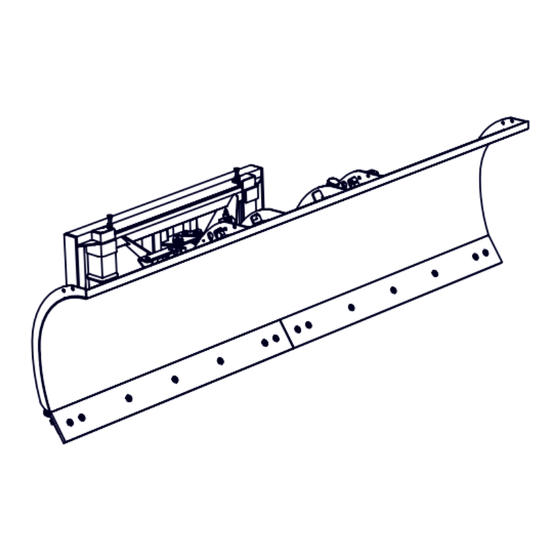
Page 14: Components And Features
Components and Features The SB series snow blades are designed to handle snow in a reliable, safe way. Its features make it the best choice for getting plowing jobs done quickly and easily. The owner or operator has the responsibility of being familiar with all the features of the SB Series and know how to operate them. -
Page 15: Main Blade Angle
Main Blade Angle The main blade is infinitely variable to any angle between 0° and 35° in each direction with dual heavy duty hydraulic cylinder. The hydraulics are protected against impact from hidden obstacles with a cross over relief valve. The relief 35°... -
Page 16: Initial Setup
Initial Setup To prevent potential injury during installation and to ensure safe working conditions, avoid working around the power unit while it is running. Shut off the power unit and ensure the brakes are applied or the wheels have been secured with wheel chocks, to prevent unwanted movement during the installation process. -
Page 17: Hydraulics
Hydraulics Hydraulic connections from the power unit to the SB snow blade are made at the snow blade. Hydraulic hoses and connectors from the snow blade to the power unit is the responsibility of the owner. The following describes the typical connection procedure, however customizing the connections is possible (mid mount loader valve, etc) and is up to the customer. -
Page 18: Field Operation
Field Operation This section describes how to safely and effectively operate the SB series snow blade in the field of operation. By following recommended procedures, a safe working environment is provided for the operator, bystanders and the area around the work site. Not all situations and conditions can be addressed, proceed with care & caution and use safety as your guide. -
Page 19: Mount The Snow Attachment
Mount the Snow Attachment Mount CAUTION Ensure your quick attach system is secure. Operational Hazard Always ensure the quick attach locks or pins • Position the hydraulic connectors away from the quick are engaged. A disengaged snow blade could attach points to prevent damage from pinching. slip out of the quick attach. -
Page 20: Snow Clearing
Snow Clearing Once the SB series snow blade is mounted and tested it is ready for snow clearing operations. The SB is designed only for snow removal operations, and works in various configurations in forward modes. How and when to use the various configurations and power unit features such as float control, will be dictated by a combination of variables: •... -
Page 21: Snow Clearing Tips - Cont
This will considerably shorten the life of your help stack the snow. wear shoes and cutting edge. This is NOT necessary • Install the HLA Snow optional rubber cutting edge for proper clearing. if the surface you are clearing should be protected •... -
Page 22: Storage
Storage Storage Safety Checklist Store the snow blade away from work area’s. Ensure all pins, latches and locks are secure. Do not permit children to play on or around the stored Guard any sharp corners. machinery. Ensure the snow blade is stable and will not move expectantly. -
Page 23: Service & Maintenance
Service & Maintenance Good maintenance is your responsibility. Poor maintenance is an invitation to trouble. To keep your SB series snow blade in good working condition, and increase pin life, periodic lubrication is essential. Servicing the grease points also helps to flush out moisture and dirt. By following a careful service and maintenance program for your snow blade, you will enjoy many years of trouble-free operation. -
Page 24: Grease
Grease: • Replace any broken zerk fittings immediately. Inspect pins and bushing components before each use. Unusual play or noise could be an indication of worn • If grease zerk will not take grease, remove and clean parts. Parts replacement should be performed by qualified thoroughly. -
Page 25: Sb4000, Sb5000 & Sb6000 Series
SB4000, SB5000 & SB6000 Series The SB6000 is illustrated below, however the grease and lubrication locations are similar on all SB4 ,5 & 6000 series. For clarity some views only show the left side, right side is identical but opposite. Lateral Float front Horizontal pivot pin... -
Page 26: Adjust Spring Trip
Adjust Spring Trip: Spring tension is set at the factory: the top end of the eye bolts are 2 ¼” above steel plate. Under normal circumstances spring tension should not require any adjustment. After a period of time or heavy use, the spring trip cutting edge may begin tripping too easily, then adjustment to the tension of the spring system may be required. -
Page 27: Wear Part Inspection & Replacement
If replacement of these parts appear excessive, consider switching to HLA Snow heavy duty carbide tipped cutting edges and high tensile long wear skid shoes. See accessories section at the back of this manual. Follow the 'Maintenance Safety Checklist' and prepare a work area. -
Page 28: Cutting Edge & Skid Shoe
Cutting Edge & Skid shoe The cutting edge is heavy and has sharp edges, use • Carefully turn the cutting edge end for end, so the caution when handling and wear heavy gloves. fresh edge is at the bottom. (or replace the cutting edge if you have flipped it previously.) The cutting edge is in two pieces, held on by a series of 5/8 x 2.25"... -
Page 29: Edgeflex
EdgeFlex For EdgeFlex equipped models, inspect these wear Cover plate parts for replacement. • Flex Cutting edge segment must be replaced when the measurement is 6.7" from the top of the retainer plate to the bottom of the cutting edge segment. Follow the 'Maintenance Safety Checklist' and prepare a work area. -
Page 30: Rubber Cutting Edge
Rubber Cutting Edge If replacing a steel edge with the rubber cutting edge, be sure to use the carriage bolts included. The Rubber cutting edge is heavy. Ask for help, use caution when handling and wear heavy gloves. The rubber cutting edge is one piece, held on by a series of 5/8 x 3.00" carriage bolts with nylon lock nuts. Rubber cutting edge: must be flipped or replaced when it is worn to 1/2”... -
Page 31: Bolt Torque Table
Bolt Torque Table These tables are offered as the suggested maximum torque values for dry (not lubricated) threaded products and are only a general guide. Check tightness of bolts periodically, replace hardware with the same strength bolt. Torque specification for bolts are identified by their head markings as shown. See the “Wheel Torque Specification”... -
Page 32: Trouble Shooting
Trouble Shooting On the following page, we have listed many of the causes and solutions to issues that you may encounter. If you encounter a issue that is difficult to solve, even after having read through this trouble shooting section, please call your local distributor or dealer. - Page 33 PROBLEM CAUSE SOLUTION Reference Check and refill hydraulic system to Low hydraulic fluid level. proper level. Allow hydraulic fluid to warm up to Cold hydraulic fluid. operating temperature. Engine R.P.M. too slow. Increase engine R.P.M. Hydraulics react slowly. Refer to Power Unit’s manual for Hydraulic pump failing.
-
Page 34: Accessories
Accessories For accessories or replacement parts, call your dealer for pricing and availability or go to hlasnow.com and click on ‘Parts’. Rubber Cutting Edge The optional rubber cutting edge is primarily used on stamped concrete or other areas where the surface is susceptible to damage. -
Page 35: Index
Index Accident Prevention ......6 oPerAtor ........9 Air-fluid . - Page 36 1 year from the date of delivery, and a commercial period of 2 years for HLA Snow 3000, 4000, 5000 and 6000 series blades from the date of delivery. Warranty is limited to the repair of the product and / or replacement of parts.
- Page 37 Notes...
- Page 38 Notes...
- Page 39 Notes...
- Page 40 8082 Rd 129 · Listowel · ON N4W 3G8 · Canada 519-291-4162 ·1-866-567-4162 · Fax 1-519-291-5388 sales@horstwelding.com · www.hlasnow.com · www.horstwelding.com...
Need help?
Do you have a question about the SnowBlade SB3000 Series and is the answer not in the manual?
Questions and answers