Table of Contents
Advertisement
Advertisement
Table of Contents

Related Manuals for HB-THERM CLEAN-5

Summary of Contents for HB-THERM CLEAN-5
- Page 1 Instruction Manual HB-CL2 Cleaning Unit...
- Page 2 Contents 2022-01 O8305-EN Instr ucti on Manual HB-CL2 Cleaning U nit HB-Therm AG Spinnereistrasse 10 (WU 3) Postfach 9006 St. Gallen Switzerland www.hb-therm.ch (Typenschild) E-Mail info@hb-therm.ch Phone +41 71 243 6-530 Translation of original instruction O8305-EN 2022-01...
-
Page 3: Table Of Contents
HB-CL2 Cleaning Unit Contents Index ....................6 General ..................8 Information about this manual ........8 Explanation of symbols ..........9 Limitation of liability ........... 10 Copyright ..............10 Warranty terms ............11 Customer Service ............11 Safety ..................12 Intended Use ............. - Page 4 HB-CL2 Cleaning Unit Contents Safety ................ 35 Requirements for the installation location ....36 Installation work ............36 6.3.1 Lock castors ..........36 6.3.2 Setting up system connections ....37 Control ................... 39 Keyboard ..............39 Operating structure ............ 41 Menu structure............
- Page 5 HB-CL2 Cleaning Unit Contents 10.1 Safety ................ 84 10.2 Fault indications............86 10.2.1 Fault indication display ....... 86 10.3 Determine the cause of a fault ........86 10.4 Troubleshooting chart ..........87 10.5 Startup after eliminating fault ........88 11 Disposal ................89 11.1 Safety ................
-
Page 6: Index
HB-CL2 Cleaning Unit Index Index Functions ............60 Access code ............65 Access rights ............63 Hydraulic connections ........28 Additional equipment .......... 29 Hydraulic scheme ..........93 Hydraulic specialist ..........14 Basic display ............40 Installation ............36 Installation location ..........36 CE Declaration of Conformity ...... - Page 7 HB-CL2 Cleaning Unit Operation ............46 Special Design ............. 8 Operation modes ..........30 Status display ............. 40 Overview ............. 24 Storage .............. 34 Structure ............24 Switching off ............58 Packing ............... 33 Switching on ............46 Personnel ..........14, 74, 84 Symbol display ...........
-
Page 8: General
HB-CL2 Cleaning Unit General 1 General 1.1 Information about this manual This manual enables the safe and efficient handling of the unit. The manual is a component part of the unit and must always be kept close to the unit readily accessible for personnel. Before starting any work, the personnel must have carefully read through and understood this manual. -
Page 9: Explanation Of Symbols
HB-CL2 Cleaning Unit General 1.2 Explanation of symbols Warnings Warnings are identified by symbols. These warnings are introduced by signal words, which express the severity of a danger. Adhere to these warnings and act cautiously in order to avoid accidents, personal injuries and damage to property. DANGER! …... -
Page 10: Limitation Of Liability
HB-CL2 Cleaning Unit General 1.3 Limitation of liability All information and notes in this Manual were compiled under due consideration of valid standards and regulations, the present status of technology and our years of knowledge and experience. The manufacturer can not be made liable for damage resulting from: ... -
Page 11: Warranty Terms
1.5 Warranty terms The warranty terms are provided in the manufacturer's terms and conditions. 1.6 Customer Service For technical information, please contact the HB-Therm representatives or our customer service department www.hb-therm.ch. Furthermore, our employees are always interested in new infor- mation and experiences resulting from the application that could be valuable for the improvement of our products. -
Page 12: Safety
HB-CL2 Cleaning Unit Safety 2 Safety This paragraph provides an overview of all important safety aspects for optimal protection of personnel as well as safe and trouble-free operation. Disregarding this Manual and safety regulations specified therein may result in considerable danger. 2.1 Intended Use The unit is designed and constructed exclusively for the intended use described here. -
Page 13: Customer's Responsibility
HB-CL2 Cleaning Unit Safety 2.2 Customer’s responsibility The device is implemented commercially. Thus the owner of the device is subject to legal industrial safety obligations. In addition to the safety instructions in this Manual, the safety, accident prevention guidelines and environmental protection regulations, applicable at the site of implementation must be complied with. -
Page 14: Personnel Requirements
HB-CL2 Cleaning Unit Safety 2.3 Personnel requirements 2.3.1 Qualifications WARNING! Danger of injury if insufficiently qualified! Improper operation can lead to serious personal injuries or property damage. Therefore: – Have all activities performed only by qualified personnel. The following qualifications are specified for different areas of activity listed in the Manual. -
Page 15: Unauthorized Persons
HB-CL2 Cleaning Unit Safety Chemicals specialist based on his or her technical training, knowledge and experience, as well as knowledge of the relevant standards and regulations, is able to carry out work with chemicals and to independently detect and avoid possible dangers. The chemicals specialist is trained for the specific location at which he or she is employed, and is familiar with the relevant standards and regulations. -
Page 16: Personal Protective Equipment
HB-CL2 Cleaning Unit Safety 2.4 Personal protective equipment When working, it may be necessary to wear personal protective equipment in order to minimise dangers to health. During work, always wear the protective equipment necessary for the particular work. Follow the information placed in the working area with regard personal safety equipment. -
Page 17: Specific Dangers
HB-CL2 Cleaning Unit Safety 2.5 Specific dangers The following section lists the residual risks that have been determined by the risk assessment. Heed the safety instructions listed here, and the warnings in subsequent chapters of this Manual, to reduce health hazards and to avoid dangerous situations. - Page 18 HB-CL2 Cleaning Unit Safety Chemicals WARNING! Danger of injury from chemicals! Depending on the type and dilution, chemicals can cause burns, irritate respiratory organs and mucous membranes and have a toxic effect if swallowed. Therefore: – Only allow work with chemicals to be carried out by qualified specialist personnel.
-
Page 19: Safety Devices
HB-CL2 Cleaning Unit Safety 2.6 Safety devices WARNING! Malfunctioning safety devices may pose a fatal risk! Safety devices must be intact in order to guarantee safety. Therefore: – Never disable safety devices. – Take care to ensure that safety devices such as main switch are always accessible. -
Page 20: Ce Declaration Of Conformity For Machinery
HB-CL2 Cleaning Unit Safety 2.7 CE Declaration of Conformity for Machinery (CE-Directive 2006/42/EG, Annex II 1. A.) Product HB-Therm Clean-5 Cleaning Device Unit types HB-CL2 HB-Therm AG Manufacturer Address Spinnereistrasse 10 (WU 3) Postfach 9006 St. Gallen Switzerland www.hb-therm.ch CE guidelines 2014/30/EU;... -
Page 21: Technical Data
HB-CL2 Cleaning Unit Technical data 3 Technical data 3.1 General Information Fig. 2: Dimensions Value Unit Max. weight HB-CL2 Value Unit Pressure measurement Measuring range 0–20 Dissolution Tolerance ±5 % of the final value 3.2 Emissions Value Unit Continuous sound pressure level <70 dB(A) 3.3 Operating conditions... -
Page 22: Connection Values
HB-CL2 Cleaning Unit Technical data 3.4 Connection values Electrical connection Grid system TN (net with protective conductor) Mains voltage U see nameplate on unit or on page 2 Maximum fusing see page 91 NOTE! The rated short-circuit current is not specified for this power range. -
Page 23: Nameplate
HB-CL2 Cleaning Unit Technical data 3.5 Nameplate The nameplate is located on the rear panel of the unit, on the inside of the service flap and on page 2 o these operating instructions. The following information can be taken from the nameplate: ... -
Page 24: Structure And Function
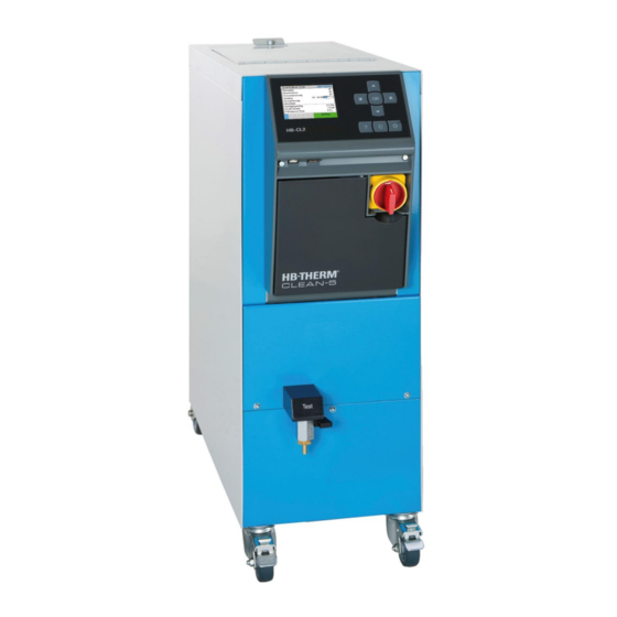
HB-CL2 Cleaning Unit Structure and function 4 Structure and function 4.1 Overview Fig. 3: Overview Keyboard and display Switch valve Tank Pump 4.2 Brief description The unit is for cleaning temperature control channels in tools, temperature control devices and the hydraulic components of these devices. -
Page 25: Functional Principle
HB-CL2 Cleaning Unit Structure and function 4.3 Functional principle The cleaning unit contains a tank, a pump and a filter basket. The integrated level measurement controls the filling level in the tank. The unit is automatically replenished and after the termination of the filling phase, the user is being informed to fill in cleaning agent. - Page 26 HB-CL2 Cleaning Unit Structure and function Switch on the unit Cleaning phase Rinsing phase Automatic filling Automatic filling Function rinse tool Leak test / Add cleaning agents Drain tool Clean tool Drain content of tank Drain tool Preservation phase with / without preservation Neutralisation phase (tank) with / without preservation with / without neutralisation...
-
Page 27: Medium
Structure and function 4.4 Medium The medium used is water that has been treated with cleaning agents, neutralization agents, or preservatives. HB-Therm recommends appropriate cleaning agents, neutralization agents, and preservatives. NOTICE! For further information, you can go to to download “Recommendations www.hb-therm.ch... -
Page 28: Connections
HB-CL2 Cleaning Unit Structure and function 4.5 Connections The connections and important components on the rear of the unit are marked as follows: Connection 1 Connection 2 Fresh water inlet Drain Emptying TEST Sample water outlet Fresh water filter Min. filling level Max. -
Page 29: Additional Equipment
HB-CL2 Cleaning Unit Structure and function 4.6 Additional equipment The following additional equipment can be installed in addition to the basic equipment for the unit ( nameplate): Additional equipment Description Keyboard-protection Transparent flap over display and controls Special Design Special design without additional description Special Design with appendix Special design with additional description in Appendix A O8305-EN 2022-01... -
Page 30: Operation Modes
HB-CL2 Cleaning Unit Structure and function 4.7 Operation modes 4.7.1 Main operating modes Cleaning During cleaning, the attached components are rinsed using a cleaning medium. The flow direction is automatically switched using the switch valve. 4.7.2 Modes of auxiliary operation Tank emptying In the Tank emptying... -
Page 31: Transport, Packing And Storage
HB-CL2 Cleaning Unit Transport, packing and storage 5 Transport, packing and storage 5.1 Safety notes for transport Improper transport ATTENTION! Damage due to improper transport! Improper transport can result in considerable material damage. Therefore: – Unit must be completely emptied (cooling and system circuit) –... - Page 32 HB-CL2 Cleaning Unit Transport, packing and storage Transport with a crane The unit can be equipped with lifting brackets (special design). Transport with a crane can be carried out under the following conditions: Crane and lifting gear must be designed for the weight of the unit.
-
Page 33: Transport Inspection
HB-CL2 Cleaning Unit Transport, packing and storage 5.3 Transport inspection Check the delivery immediately on receipt for completeness and transport damage. If externally detectable transport damage is found, proceed as follows: Do not accept the delivery, or only with reservation. ... -
Page 34: Symbols On The Packing
HB-CL2 Cleaning Unit Transport, packing and storage 5.5 Symbols on the packing Protect against wetness Protect packages against wetness and keep dry. Fragile Identifies packages with fragile or sensitive content. Handle package with care, do not drop and do not subject to shock loads. -
Page 35: Installation And Initial Commissioning
HB-CL2 Cleaning Unit Installation and initial commissioning 6 Installation and initial commissioning 6.1 Safety Personnel The installation and commissioning must only be carried out by qualified personnel. Work on the electrical system must only be carried out by certified electricians. -
Page 36: Requirements For The Installation Location
HB-CL2 Cleaning Unit Installation and initial commissioning 6.2 Requirements for the installation location WARNING! Improper installation can cause risk of injury and fire! Improper installation can lead to severe personal injury or material damage. Therefore: – Observe and comply with the requirements at the installation site Install the unit under the following conditions: ... -
Page 37: Setting Up System Connections
HB-CL2 Cleaning Unit Installation and initial commissioning 6.3.2 Setting up system connections WARNING! Danger from hydraulic energy! On using unsuitable pressure lines and connectors, the danger exists that liquids under high pressure can escape and cause severe or fatal injuries. Therefore: –... - Page 38 HB-CL2 Cleaning Unit Installation and initial commissioning Connect , connection 1 and 2 Connect, connection 1 (S1) to the entry of the component. Connect, connection 2 (S1) to the entry of the component. NOTICE! If the component to be cleaned may only be passed through in one direction, the Interval flow inversion must be set to „OFF“.
-
Page 39: Control
HB-CL2 Cleaning Unit Control 7 Control 7.1 Keyboard Fig. 11: Keyboard and display Key function in basic Key function within menu Key function with active parameter display adjustment no function Navigate upwards. Increase values. Switch from „one tenth setting“ to no function Navigate to the left. - Page 40 HB-CL2 Cleaning Unit Control Basic display Fig. 12: Basic display Pos. Designation Display Menu bar Date and time Symbol field Display active functions and details Address field Display unit address Unit Unit for actual values displayed Operating mode and colour- Display of current operating mode and pending alarms and coded condition display warnings...
-
Page 41: Operating Structure
HB-CL2 Cleaning Unit Control 7.2 Operating structure Navigate through the menu structure as follows: Use the key to display step-by-step the next lowest hierarchy level starting from the basic display. Use the key to display step-by-step the next highest hierarchy level up to the basic display. -
Page 42: Menu Structure
HB-CL2 Cleaning Unit Control 7.3 Menu structure NOTE! Depending on the software version used, the menu structure and the parameter values can deviate from the following table. Display Functions Skip current phase Emptying tank Rinse tank Rinse tool Preserve tool Rinse tool/preserve Display Actual values... - Page 43 HB-CL2 Cleaning Unit Control Level Level premonition Setting Remote mode Address Protocol Transfer rate 19200 Parity none Data bit Stop bit Serial recording cycle Date/Time Time HH:MM Date Time zone Switch over summer/winter autom. Time zone offset UTC Units Temperature scale °C Pressure scale Miscellaneous...
- Page 44 HB-CL2 Cleaning Unit Control Nominal conc. cleaning Neutralisation agent Density neutralization agent 1.00 g/ml Limit value neutral. pH low Limit value neutral. pH high Offset neutralization 1.00 Factor neustralization 1 1.00 Factor neustralization 2 1.00 Factor neustralization 3 1.00 Preservation agent Density preservation agent 1.00 g/ml...
- Page 45 HB-CL2 Cleaning Unit Control User profile Standard Operating release Code 1234 Language Key press volume Fault finding Logbook Alarms Logbook Alarms Logbook agent Logbook agent Save/Load Start USB Software Update Recording USB Load configuration data Save configuration data Load parameter data Save parameter data Save error and operation data Save Serviceinfo...
-
Page 46: Operation
HB-CL2 Cleaning Unit Operation 8 Operation 8.1 Switching on Switch on unit as follows: Turn the main switch to position "I". Unit initialisation runs. The indication "Ready-to-operate" appears on the display. Fig. 14: Main switch O8305-EN 2022-01... -
Page 47: Define Agent
HB-CL2 Cleaning Unit Operation 8.1.1 Define agent Select agent As long as the cleaning, neutralisation, pre-preservation and pre- servationagents are not determined, the warning Agent not defined will be displayed. The agents and properties are to be selected as follows: Set the cleaning agent parameter to the cleaning agent used. - Page 48 NOTICE! If you encounter problems with the determination of the parameter, please contact the nearest HB-Therm representative. Apply properties with Check input. Change agent Proceed as follows in order to subsequently change the agent:...
-
Page 49: Normal Operation
HB-CL2 Cleaning Unit Operation 8.1.2 Normal operation Switch on cleaning unit as follows: WARNING! Damages if switched off early! If the cleaning cycle is not completely finished, the connected components can be damaged. Therefore: – Plan ample time for a complete cleaning. –... - Page 50 HB-CL2 Cleaning Unit Operation 8.1.2.1 Cleaning phase Check seal / add cleaning agent Proceed as follows if the warning Add agent is displayed: Acknowledge horn with the key. Proceed to check the seal in the external circuit. If a leak appears, cancel the cleaning cycle and switch off the unit with the key.
- Page 51 HB-CL2 Cleaning Unit Operation Cyclical change of the flow The flow direction is changed cyclical during the cleaning, pre- direction preservation, rinsing and preservation phases to obtain a more efficient cleaning rate. If necessary, set the desired interval for the change of flow direction: Display the menu page Settings \...
- Page 52 HB-CL2 Cleaning Unit Operation 8.1.2.2 Neutralization phase In this phase, the cleaning agent is neutralized with the neutralizing agent so that no aggressive medium is pumped into the outlet. Neutralization occurs only in the interior tank. NOTICE! Local sewage regulations must be followed. Information about neutralization can be taken from the safety sheet or you can ask the manufacturer of the cleaning agent about it.
- Page 53 HB-CL2 Cleaning Unit Operation Neutralize medium If the warning Neutralization is shown, proceed as follows: Acknowledge horn with the key. Place a measuring container under the connection and open the tap until the measuring container is completely full. Empty the medium in the measuring container into the tank through the tank opening.
- Page 54 HB-CL2 Cleaning Unit Operation Neutralization time If necessary, before switching on neutralization, set the neutralization time: Display the menu page Settings \ Cleaning. Time of neutralization to the desired value. Fig. 26: Setting neutralization time 8.1.2.3 Pre-preservation phase In this phase the connected components are being neutralised and pre-preserved with pre-preservation agents.
- Page 55 HB-CL2 Cleaning Unit Operation Add pre-preservation agent Proceed as follows if the message Add agent is displayed: Acknowledge horn with the key. Fill indicated pre-preservation agent quantity in through the tank opening in the tank. WARNING! Risk of injury due to chemicals! Chemicals can cause chemical burns, depending on the type and dilution, cause irritation of the membrane and respiratory system and be toxic if...
- Page 56 HB-CL2 Cleaning Unit Operation Time of tool rinsing If necessary, set the desired time for the tool rinsing: Display the menu page Settings \ Cleaning. Set parameter Time of tool rinsingto the desired value. Fig. 29: Setting Time of tool rinsing O8305-EN 2022-01...
- Page 57 HB-CL2 Cleaning Unit Operation 8.1.2.5 Preservation phase In this phase the connected components are treated with the preservation agent, in order to protect them and avoid rusting during stprage- At the end of the preservation phase the connected components are emptied again. The preservation phase is either carried out automatically, omitted or queried depending on the setting of the preservation...
-
Page 58: Switching Off
HB-CL2 Cleaning Unit Operation 8.1 Switching off After use, switch the unit off as follows: Press the key. The cleaning unit switches off. In the operatingmodedisplay, "Ready to operate" is indicated. Turn the main switch to "0". Fig. 32: Main switch ATTENTION! Turning it off prematurely will damage it! If the cleaning cycle is not complete, that may lead... -
Page 59: Emergency Stop
HB-CL2 Cleaning Unit Operation 8.2 Emergency stop In dangerous situations, the unit must be stopped as quickly as possible and the power supply switched off. Emergency stop Proceed as follows in a hazardous situation: Turn the main switch to "0". Disconnect from the mains or disconnect all phases of the external power supply and secure them against being switched on again. -
Page 60: Functions
HB-CL2 Cleaning Unit Operation 8.3 Functions 8.3.1 Skip current phase The fill (preparation), cleaning operation (cleaning), tool rinsing (rinsing/preservation) can be skipped before they are over. To do so, proceed as follows: Display menu page Functions. Select the parameter Skip current phase and press the key. -
Page 61: Rinse Tank
HB-CL2 Cleaning Unit Operation 8.3.3 Rinse tank The tank can be rinsed using the servicing function. Proceed as follows to rinse the tank: Hook up fresh water intake (E) to the plumbing. Attach emptying (G) to a container. Display menu page Functions. Select Rinse tank and activate it using the... -
Page 62: Rinse Tool
HB-CL2 Cleaning Unit Operation 8.3.4 Rinse tool Using the Rinse tool function, the attached components are rinsed with fresh water Proceed as follows to rinse the attached components: Display menu page Functions. Select Rinse tool and activate it using the key. -
Page 63: Define Access Rights
HB-CL2 Cleaning Unit Operation 8.4 Define access rights 8.4.1 Set user profile Function In order to avoid operating error and to improve clarity, menus, functions and parameters are suppressed corresponding to the set user profile. Differentiating user profiles A differentiation is made between the following user profiles. User profile Code User/Characteristic Standard... -
Page 64: Set Operating Release
HB-CL2 Cleaning Unit Operation 8.4.2 Set operating release Function With the operating release level, it is determined which functions or values can be changed. If it is attempted to change locked values, a corresponding warning text appears on the display. Level Operating release Levels of operating release... -
Page 65: Change Access Code
When the unit is delivered, the access code is 1234. NOTE! For protection against misuse of the unit, change the access code immediately after commissioning. If the current code is lost, please contact the nearest HB-Therm representative. Change access code To change the access code: Display menu page Profile... -
Page 66: Settings
HB-CL2 Cleaning Unit Operation 8.5 Settings 8.5.1 Setting time zone, date and time Set time zone By default, date and time of the unit are set to Central European Time (CET) at delivery. To accommodate for different time zones, date and time must be set manually before commissioning. In this case, please proceed as follows: Open the Setting \ Date / Time... -
Page 67: Level
HB-CL2 Cleaning Unit Operation 8.5.1 Level Adjust nominal value of fill level for Proceed as follows in order to set the nominal value of the filling cleaning level for cleaning: Display the menu page Settings \ Cleaning. Set parameter Nominal value of filling level cleaning to the desired value. -
Page 68: Monitoring
HB-CL2 Cleaning Unit Operation 8.1 Monitoring 8.1.1 Tank temperature Function The temperature in the tank is continuously monitored. If the limit temperature is exceeded, the "Excessive temperature in the circuit" alarm goes off. Setting monitoring temperature Monitoring the temperature in the tank is to be set as follows: Display the menu page Settings \ Miscellaneous. -
Page 69: Explorer Window
HB-CL2 Cleaning Unit Operation 8.2 Explorer window The Explorer window displays the directories and files on the inserted USB data carrier. Directories with are opened with the key. Directories with are closed with the key. NOTE! Depending on the number of files and directories on the USB data carrier, it can take several minutes before the directory structure is displayed. -
Page 70: Save/Load
In case of failure, the service information can be stored on an USB device for fault diagnosis by a representative of HB-Therm. WARNING! Damage due to wrong settings! Loading wrong parameter or configuration data can lead to malfunction or total breakdown. - Page 71 HB-CL2 Cleaning Unit Operation Loading data Proceed as follows in order to load data to the unit from a USB data carrier: Display menu page Save/Load. Connect USB data carrier to front connector. Select the data to be loaded and confirm with the key.
-
Page 72: Recording Actual Data
HB-CL2 Cleaning Unit Operation 8.3.1 Recording actual data Function When the Record USB function is activated, the values selected in Setting \ Recording USB are written to the USB data carrier.- A new recording file is created each day. If saving to the USB data carrier is not possible, a corresponding warning is displayed.- Start recording Proceed as follows to start recording actual data to a USB data... - Page 73 Device type NOTICE! The GIF-ID can be seen under Display \ Module. Visualize the data recorded To visualize and prepare the actual data recorded, the VIP (Visualisation programme – Recording of actual values) software can be downloaded from www.hb-therm.ch. O8305-EN 2022-01...
-
Page 74: Maintenance
HB-CL2 Cleaning Unit Maintenance 9 Maintenance 9.1 Safety Personnel Maintenance tasks described here can be performed by the operator, unless otherwise indicated. Some maintenance tasks must only be carried out by qualified personnel or by the manufacturer exclusively. If this is required, it is pointed out separately in the description of the respective faults. -
Page 75: Open The Unit
HB-CL2 Cleaning Unit Maintenance 9.2 Open the unit The unit has to be opened for specific maintenance work. Only to be carried out by a specialist or instructed person. Necessary tools (depending on unit status): Torx screwdriver. ... - Page 76 HB-CL2 Cleaning Unit Maintenance Use a screwdriver to loosen and remove the screw in the cover plate. Fig. 51: Loosen screws Pull the cover plate approx. 1 cm to the rear and lift off upwards. Fig. 52: Remove cover plate Pull the side plate slightly upwards.
-
Page 77: Maintenance Schedule
If increased wear is detected at regular inspections then the required maintenance intervals must be shortened by the customer to correspond with the actual signs of wear. Contact the HB-Therm distributors for questions on maintenance work ( www.hb-therm.ch). Interval Assembly / Component Maintenance work... -
Page 78: Maintenance Tasks
HB-CL2 Cleaning Unit Maintenance 9.4 Maintenance tasks 9.4.1 Cleaning Clean the unit under the following conditions: Only clean the outer parts of the unit with a soft, moist cloth. Do not use any aggressive cleaning agents. 9.4.2 Clean tank, filter basket Cleaning the tank and filter basket ... -
Page 79: Pressure Measurement
Necessary equipment no special equipment Optionally, test equipment can be used for the pressure measurement. For further information go to www.hb-therm.ch Procedure Switch off the unit. Depressurize main line. Main line pressure on menu page Display \ Actual value must indicate 0.0 bar ±0.1 bar. -
Page 80: Level Measurement
( Fig. 55) using a nozzle. 11. Manually fill tank until the menu page Display \ Actual values shows 100 %. No water may flow over the top of the tank. NOTICE! If you have problems, consult the HB-Therm staff www.hb-therm.ch). O8305-EN 2022-01... -
Page 81: Software Update
Necessary tools: USB data carrier with the current software The latest software can be acquired from the HB-Therm representative ( www.hb-therm.ch). NOTICE! Only USB data carriers in FAT32 format are supported. -
Page 82: Gain Access To Components
HB-CL2 Cleaning Unit Maintenance Checking the software version In the basic display, press the key. The current software version appears at the top right. 9.4.6 Gain access to components In order to have clear access to the system components to change them if necessary, the unit must first be opened. -
Page 83: Logbook Agent
HB-CL2 Cleaning Unit Maintenance 9.5 Logbook agent Every input of agent, entry of results or interruption of cleaning is chronologically recorded in the logbook agent (no more than 100 entries). The entries can be displayed as follows: Display menu page Fault search \ Logbook agent Select the entry desired using the or the... -
Page 84: Faults
In the case of faults, which can not be remedied by the following instructions, contact the HB-Therm representative ( www.hb-therm.ch). For error diagnoses, service information can be saved to a USB data carrier and sent to the HB-Therm representative ( page 70). 10.1 Safety ... - Page 85 HB-CL2 Cleaning Unit Faults Maintenance / repair work carried WARNING! out improperly Danger of injury due to maintenance / repair work carried out improperly! Improper maintenance / repair work can lead to severe personal injury or material damage. Therefore: – Before starting work, ensure that there is sufficient space for assembly.
-
Page 86: Fault Indications
Acknowledge horn with the key. is displayed in the symbol field. Determine the cause of the fault. If required, contact the HB-Therm representative ( www.hb-therm.ch). Acknowledge alarm with the key. 10.3 Determine the cause of a fault Cause of a fault... -
Page 87: Troubleshooting Chart
HB-CL2 Cleaning Unit Faults 10.4 Troubleshooting chart Fault Possible cause Rectification Rectified by Undercurrent pump Not connected to the correct Connect to the correct mains Certified mains voltage voltage electrician Overcurrent pump Pump defective Repair or replace pump Qualified personnel Phase missing Mains connection not made Make mains connection... -
Page 88: Startup After Eliminating Fault
HB-CL2 Cleaning Unit Faults 10.5 Startup after eliminating fault After remedying the fault, the following steps should be taken to re- start the system: Reset the Emergency Off devices. Acknowledge the fault at the control unit. Ensure that no one is in the danger zone. Start up in accordance with the instructions in the "Operating"... -
Page 89: Disposal
HB-CL2 Cleaning Unit Disposal 11 Disposal 11.1 Safety Personnel Disposal must only be carried out by qualified personnel. Work on the electrical system must only be carried out by certified electricians. Work on the hydraulic system must only be carried out by qualified hydraulics technicians. -
Page 90: Spare Parts
Therefore: – Only use original spare parts from the manufacturer. Purchase spare parts through the HB-Therm representative ( www.hb-therm.ch). The spare parts list can be found in Appendix B of this operating manual. On use of non-approved spare parts, any guarantee or service claims are forfeited. -
Page 91: Technical Information
HB-CL2 Cleaning Unit Technical information 13 Technical information 13.1 Electrical circuit diagram 380–415 V 200–220 V 440–480 V Maximum pre-fuse: 3x16 A 3x16 A 3x16 A NOTICE! On units without frequency converter To protect against electric shock, the use of a residual current circuit-breaker (RCD) Type A is recommended. - Page 92 HB-5CL2_4xx_2xx HB-CL2 Cleaning Unit Technical information X 107 X 109 USR-51 HA 1 L1 L2 L3 PE X 103 X 101 X 106 XT 1 TC 1 QS 1 X 104 X 105 KM 1 X 14 X 16 X 20 X 22 X 21 X 17 X 4 X 51.2 X 23...
-
Page 93: Hydraulic Scheme
HB-CL2 Cleaning Unit Technical information 13.2 Hydraulic scheme HB-CL2 YV 4 YV 3 YV 1 7.18 12.3 O8305-EN 2022-01... -
Page 94: Item Location
HB-CL2 Cleaning Unit Technical information 13.3 Item location Side view left Side view right O8305-EN 2022-01... - Page 95 HB-CL2 Cleaning Unit Technical information Cold water module YV 4 YV 1 YV 3 7.18 BL 1 Tank Electric components O8305-EN 2022-01...
- Page 96 HB-CL2 Cleaning Unit Technical information Front HA 1 X 105 X 104 O8305-EN 2022-01...
-
Page 97: Legend
HB-CL2 Cleaning Unit Technical information 13.4 Legend Designation only with version Connection 1 Connection 2 Fresh water inlet Discharge water outlet Test Drain Cold water module Switch module Fresh water inlet filter Non-return valve filling 7.18 Non-return valve drain Tank Level indicator 12.3 Test of the cut-off valve...
Need help?
Do you have a question about the CLEAN-5 and is the answer not in the manual?
Questions and answers