Table of Contents
Advertisement
Contents
Contents...................................................................................................................................... 1
1.
Introduction ...................................................................................................................... 3
1.1.
General...................................................................................................................................... 3
1.2.
Versions .................................................................................................................................... 4
2.
Safety precautions ............................................................................................................ 6
2.1.
Explanation of the pictograms .................................................................................................. 6
2.2.
General warnings ...................................................................................................................... 6
2.3.
Using the machine .................................................................................................................... 7
2.4.
Cleaning and maintenance ........................................................................................................ 7
2.5.
Noise level ................................................................................................................................ 8
3.
Transport, installation, dismantling.................................................................................. 9
3.1.
Transport................................................................................................................................... 9
3.2.
Installing the machine............................................................................................................... 9
3.3.
Connecting the machine to the power supply ........................................................................... 9
3.4.
Dismantling............................................................................................................................... 9
4.
Description of the machine ............................................................................................ 10
4.1.
Safety warnings....................................................................................................................... 10
4.2.
Brief description of the machine's principle ........................................................................... 10
4.3.
Main parts ............................................................................................................................... 11
Description ............................................................................................................................... 12
4.4.
Operating controls................................................................................................................... 13
4.4.1. Mains switch ........................................................................................................................... 13
4.4.2. Start switch ............................................................................................................................. 13
4.4.3. Safety cut-out.......................................................................................................................... 14
5.
Using the machine.......................................................................................................... 15
5.1.
Safety warnings....................................................................................................................... 15
5.2.
Switching on the power supply............................................................................................... 15
5.3.
Fitting and threading the elastic cord...................................................................................... 16
5.4.
Adjusting the cord tension ...................................................................................................... 16
5.5.
Using the machine .................................................................................................................. 17
5.6.
Starting points and switching options ..................................................................................... 18
5.6.1. Pre-switching .......................................................................................................................... 18
5.6.2. Post-switching......................................................................................................................... 18
5.6.3. Pulse-switching....................................................................................................................... 18
5.6.4. Changing the switching option. .............................................................................................. 18
5.7.
Emergency stop....................................................................................................................... 18
5.8.
Stopping the machine and switching off the power supply .................................................... 18
6.
Cleaning and simple maintenance.................................................................................. 19
6.1.
Cleaning the interior of the machine....................................................................................... 19
6.2.
Weekly maintenance............................................................................................................... 20
7.
Maintenance ................................................................................................................... 21
7.1.
Safety warnings....................................................................................................................... 21
7.2.
Turning the machine by hand ................................................................................................. 21
7.3.
Basic settings .......................................................................................................................... 22
7.3.1. Alignment at the reference point............................................................................................. 22
7.3.2. Checking the setting of the rotor............................................................................................. 22
Operation Manual Axro binder
For Parts & Service 1-877-862-6699
Page 1
Advertisement
Table of Contents

Summary of Contents for CYKLOP EMT-Axro
-
Page 1: Table Of Contents
Contents Contents............................1 Introduction ........................3 1.1. General............................3 1.2. Versions ............................ 4 Safety precautions ......................6 2.1. Explanation of the pictograms ....................6 2.2. General warnings ........................6 2.3. Using the machine ........................7 2.4. Cleaning and maintenance ......................7 2.5. - Page 2 7.3.3. Checking the position of the needle..................23 7.3.4. Clamping pressure between the rotor and stator..............24 7.4. Six-monthly maintenance (to be carried out by qualified personnel) ........25 7.4.1. Cleaning and adjusting the motor brake ................. 25 7.4.2. Adjusting the knot release....................... 25 7.4.3.
-
Page 3: Introduction
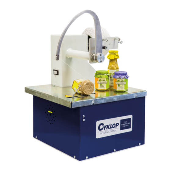
Introduction 1.1. General The Axro binder is used to bind products such as bunches of flowers with elastic cord. The standard machines are assembled and adjusted for the use of elastic cord with 1 rubber core. This elastic cord is about 1 mm thick. On the customer's request, binders can also be assembled and adjusted for use with 3K elastic cord. -
Page 4: Versions
1.2. Versions The standard EMT-Axro binder is available in a number of versions. The following tables give a description of a number of specific versions: Article No. Article name Description 87101400 Axro-RLC Standard machine, driven by a 1-phase hollow-shaft through motor with brake. - Page 5 Article No. Article name Description 87101500 Axro-FQC Standard machine, driven by a 3-phase, 230 V, through hollow-shaft motor with brake. Equipped with a 87101591 frequency controller for a faster binding cycle. This binder is particularly suitable for installation on/in a (flower) line. The start switch is suspended from the needle shaft The top plate can be lifted off the machine: a safety cut-out then switches off the machine.
-
Page 6: Safety Precautions
Safety precautions 2.1. Explanation of the pictograms This pictogram is used for an urgent warning This pictogram is used for a serious warning This pictogram is used for an electrical hazard 2.2. General warnings The machine may be used only by operators who know, understand and obey all safety precautions. -
Page 7: Using The Machine
2.3. Using the machine Persons who are not aware of the following safety precautions may NOT operate the machine. The machine may never be switched on when it is open (with the top plate removed). If anything unexpectedly goes wrong, always remove the plug from the socket immediately, or switch the mains switch to ‘0’! In the event of a malfunction, never touch the moving parts. -
Page 8: Noise Level
Once the maintenance work has been completed always replace any guards removed during the work. Never bridge the safety cut-out! Note: the cutting blade is sharp. Never adjust the safety clutch such that it is too tight, or even locked. The indicative force for the operation of the clutch is 3 kg imposed on the needle's point. -
Page 9: Transport, Installation, Dismantling
Transport, installation, dismantling 3.1. Transport The machine weighs about 50 kg. A transport frame is available for the binder. The frame is fitted with castors, and is intended for use in moving the machine short distances. Once the binder has been moved always relock the castor brakes. 3.2. -
Page 10: Description Of The Machine
Description of the machine 4.1. Safety warnings Make sure that you - and others - do not place your hands under the needle! If anything unexpectedly goes wrong, always remove the plug from the socket immediately, or switch the mains switch to ‘0’! Never bridge the safety cut-out! 4.2. -
Page 11: Main Parts
4.3. Main parts Figure 1: Main parts of the Axro binder Figure 2: The standard version of the Axro binder Operation Manual Axro binder Page 11 For Parts & Service 1-877-862-6699... -
Page 12: Description
Name Description Reel holder This holds the reel of binding material (elastic cord) Elastic brake The knurled nuts are turned to adjust the tension of the elastic cord binding the product Clamping Secures the cord during the tying process. mechanism Conical gear wheel This fixed transmission drives the various parts of the machine. -
Page 13: Operating Controls
4.4. Operating controls 4.4.1. Mains switch The machine is equipped with an orange mains switch to switch the power supply on or off. Figure 3: Mains switch used for the various versions Set the mains switch to 1 to switch on the power supply. Set the mains switch to 0 to switch off the power supply. -
Page 14: Safety Cut-Out
Figure 5: Start switch fitted to top-switching version All FQC versions are equipped with a green pushbutton at the back of the machine. This can be pushed to start the machine to re-feed elastic cord, see Figure 6. Figure 6: Version fitted with pushbutton 4.4.3. -
Page 15: Using The Machine
Using the machine 5.1. Safety warnings Persons who are not aware of the following safety precautions may NOT operate the machine. The machine may never be switched on when it is open (with the top plate removed). If anything unexpectedly goes wrong always remove the plug from the socket immediately, or switch the mains switch to ‘0’! In the event of a malfunction, never touch the moving parts. -
Page 16: Fitting And Threading The Elastic Cord
5.3. Fitting and threading the elastic cord Figure 7: Elastic cord threaded into the machine Figure 8: Fitting and threading the elastic cord A reel of elastic cord is fitted and threaded into the machine as follows (see Figure 8): 1. -
Page 17: Using The Machine
5.5. Using the machine Note: on contacting the start switch the machine will begin operation. The needle will then descend rapidly. Do not place any part of your body (hands, fingers, etc.) under the needle. The needle can injure your hand. Warn other people of this hazard. Make sure that no-one places their hand on the start switch. -
Page 18: Starting Points And Switching Options
5.6. Starting points and switching options The time at which the machine is started depends on the selected switching operation. Three switching options are available: 5.6.1. Pre-switching The machine is started as soon as the switching pin is operated, and the product is bound. This switching option is generally used when small products are to be bound rapidly after each other. -
Page 19: Cleaning And Simple Maintenance
Cleaning and simple maintenance Before cleaning or maintenance, always switch off the machine by removing the plug from the socket! Regular cleaning is extremely important if the machine is to be kept in good condition. Good cleaning is important to prevent the build-up of dirt and growth of mould! Cleaning can be carried out using a brush or a damp cloth. -
Page 20: Weekly Maintenance
6.2. Weekly maintenance The weekly maintenance may be carried out only by operators who understand and obey the following instructions: Switch off the power supply to the machine and remove the plug from the socket. Remove the top plate. Clean the machine with a brush or compressed air Oil the pivoting points and the rollers of the catcher and releaser... -
Page 21: Maintenance
Maintenance The manufacturer's warranty never covers damage caused by inexpert use, use of the machine for purposes other than which it is intended, or modifications made by the user or third parties. 7.1. Safety warnings The following maintenance work may be carried out only by qualified personnel who have read and understood the maintenance instructions. -
Page 22: Basic Settings
7.3. Basic settings Figure 11: Basic settings 7.3.1. Alignment at the reference point The binder must be aligned correctly at the reference point if a suitable knot is to be tied. The binder is adjusted to the correct setting in the factory. However, after maintenance it may be necessary to realign the binder at the reference point. -
Page 23: Checking The Position Of The Needle
Insert an object of a diameter of 6 mm (for example, a screwdriver) in the opening in the rotor shaft (F). Loosen the clamping bush (G) with a 22-mm spanner. Turn the shaft until the reference mark on the rotor (C) is aligned to the reference mark on the stator (D). -
Page 24: Clamping Pressure Between The Rotor And Stator
7.3.4. Clamping pressure between the rotor and stator The clamping pressure between the rotor and stator depends on the binding material that is used. The following check needs to be carried out to ensure that optimum clamping is achieved: Fit a reel of binding material, and thread it through the machine in the customary manner. Allow the machine to complete a number of strokes. -
Page 25: Six-Monthly Maintenance (To Be Carried Out By Qualified Personnel)
7.4. Six-monthly maintenance (to be carried out by qualified personnel) Switch off the power supply to the machine and remove the plug from the socket. Remove the worktop, side panels and the cover from the crank mechanism. Clean the machine with a brush or compressed air. 7.4.1. -
Page 26: Checking The Needle Drive
7.4.3. Checking the needle drive Check that the belt of the needle drive (C) is not damaged, and that the automatic tensioner (A) is working correctly. Figure 14: Checking the needle drive 7.4.4. Checking the tying unit Dismantle the tying unit Remover the catcher (D) Remove the releaser (E) Check the bearing bushes and shafts of the... -
Page 27: Checking The Cutting Blade
Lubricate the binder in accordance with the weekly maintenance schedule, i.e.: Oil the pivoting points and the rollers of the catcher and releaser. Grease the main curve Grease the conical gear wheels Grease the chain (The lubricants to be used are stated in Section 7.6) 7.4.5. - Page 28 Figure 16: Adjusting the cutting blade Operation Manual Axro binder Page 28 For Parts & Service 1-877-862-6699...
-
Page 29: Checking The Safety Clutch
7.5. Checking the safety clutch Never adjust the safety clutch such that it is too tight, or even locked. The indicative force for the operation of the clutch is 3-4 kg imposed on the needle's point. An excessively tight clutch can cause severe injury. The safety clutch must operate correctly to protect the machine's operator. -
Page 30: Troubleshooting
Troubleshooting Problem Possible cause and solution The binder does not work at all Check the power supply. Check that the top plate is fitted correctly to the machine, and that the safety cut-out is pressed in. Activate the start switch again. If the needle does The needle stops mid-way, or now stop correctly then the top plate may be fitted irregularly... - Page 31 Use an Allen key (6 mm) to turn the machine by The cord flies off the product or out hand. of the machine Check whether the cord is clamped properly by the rotor at the right time. Pull on the clamped cord to check that it cannot readily be drawn out of the rotor and stator.
-
Page 32: Annex 1. Machine Data And General Drawing
Bijlage 1. Machine data and general drawing B 1.1. Machine data Capacity : cycle time 0.67 sec. Clear height : 155 mm Clear depth : 260 mm Power supply : 230V / 50 Hz 200V / 50 Hz 200V / 60 Hz (depending on the version) : 100-120V / 50 Hz 100-120V / 60 Hz... -
Page 33: B 1.2. General Drawings
B 1.2. General drawings RLC-Binder FQC-Binder Operation Manual Axro binder Page 33 For Parts & Service 1-877-862-6699... -
Page 34: Annex 2. Diagrams
Bijlage 2. Diagrams 1. Control circuit diagram, Axro-RLC 230V 2. Control circuit diagram, Axro-RLC Basic 3. Control circuit diagram, Axro-RLC Pulse 4. Control circuit diagram, Axro-FQC page 1 5. Control circuit diagram, Axro-FQC page 2 Operation Manual Axro binder Page 34 For Parts &... - Page 35 For Parts & Service 1-877-862-6699...
- Page 36 For Parts & Service 1-877-862-6699...
- Page 37 For Parts & Service 1-877-862-6699...
- Page 38 For Parts & Service 1-877-862-6699...
- Page 39 For Parts & Service 1-877-862-6699...
Need help?
Do you have a question about the EMT-Axro and is the answer not in the manual?
Questions and answers