Table of Contents
Advertisement
Quick Links
Advertisement
Table of Contents

Related Manuals for Deditec RO-INTERFACE-ETH


Summary of Contents for Deditec RO-INTERFACE-ETH
- Page 1 RO-INTERFACE-ETH Hardware-Description Oktober 2010...
- Page 2 2.5.1. Definition of LEDs 3. Configuring the module 3.1. Configuration via DELIB Configuration utility 3.2. Configuration via internal web server 3.3. Factory settings 4. Firmware Update 4.1. DEDITEC Flasher 4.2. Web interface 5. Restore basic configuration 5.1. Restore IP address Index | Seite...
- Page 3 INDEX 5.2. Restore firmware 6. Software 6.1. Using our products 6.1.1. Access via graphical applications 6.1.2. Access via the DELIB driver library 6.1.3. Access via protocol 6.1.4. Access via provided test programs 6.2. DELIB driver library 6.2.1. Overview 6.2.2. Supported operating systems 6.2.3.
- Page 4 Introduction Introduction | Seite...
-
Page 5: General Remarks
1.1. General remarks First of all, we would like to congratulate you to the purchase of a high quality DEDITEC product. Our products are being developed by our engineers according to quality requirements of high standard. Already during design and development we take care that our products have -besides quality- a long availability and an optimal flexibility. -
Page 6: Hardware Description
Hardware description Hardware description | Seite... -
Page 7: Overview Screen
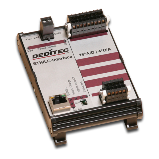
2. Hardware description 2.1. Overview screen The figure shows the control module with ethernet interface (left side) combined with an input/output module (right side). The figure shows the control module with ethernet interface (left side) combined with a flexible connector input/output module (right side). Hardware description | Seite... - Page 8 2.2. Technical data Single power supply +7V..+24V DC 10/100 Mbit/sec Ethernet interface Input/output access over TCP/IP WEB interface Configuration over web interface 9 Control LEDs RJ45 Socket Timeout feature providing ability to disconnect outputs for safety reasons Expandable in 16 gradations Can be combined without any problem to other modules of the RO series Windows driver library DELIB Hardware description | Seite...
- Page 9 2.3. Plug-in connector of the module 2.3.1. Power supply The input-power-supply-range lies between +7V and +24V DC.The power supply can be realized with a standard AC/DC adaptor with 1A output current. A suitable plug-in connector is delivered. 2.3.2. Ethernet interface The network connection is provided by a RJ45 socket.
- Page 10 2.4. Buttons of the module Left Button: Reset IP address to default (see chapter 5.1) Right Button: Reset firmware to factory settings. (see chapter 5.2) Hardware description | Seite 10...
- Page 11 2.5. Controll LEDs The Ethernet module has a series of control LEDs. They are used for easy visual indication of various state functions. While switching the module on, in normal operating mode, the module should signalize the following sequence: approx. 20 sec after switching the module on, LED 1 and 2 are flashing briefly. ->...
-
Page 12: Configuring The Module
Configuring the module Configuring the module | Seite 12... - Page 13 Module name IP address Net mask Default gateway DNS server Additionally with this tool all DEDITEC ethernet devices in the LAN network are displayed. The following pages describe how it works... Configuring the module | Seite 13...
- Page 14 Start DELIB Configuration utility as follows: Start -> Programs -> DEDITEC -> DELIB -> DELIB Configuration Utility 1. Module Selection: select RO-ETH 2. Find and configure RO-ETH Module Configuring the module | Seite...
- Page 15 1. Scan RO-ETH modules: So you can find all DEDITEC ETH modules on local ethernet stream. Therefore we use an ethernet protocol which will not be routed. Because of that you can configure only modules which are connected to the bus. The advantage of this method is, that you can find modules which are not in the same sub net, of which you are configuring.
- Page 16 Here you can change the module name according to your wishes 1. You can change module name, IP address, net mask, default gateway and DNS server. 2. Write new Values to Module. Notice: At the configuration of the RO-ETH module should be paid attention to the IP address.
- Page 17 3.2. Configuration via internal web server The RO-ETH module has an own web server by which it can be configured, too. Configuring the module | Seite 17...
- Page 18 3.3. Factory settings The factory settings of the ethernet module include following settings: IP address: 192.168.1.1 The factory settings can be restored by pushing the left button -> see chapter IP address 192.168.1.1 Subnet mask 255.255.255.0 Standard gateway 192.168.1.254 Configuring the module | Seite 18...
-
Page 19: Firmware Update
Firmware Update Firmware Update | Seite 19... - Page 20 Download the latest firmware inclusive software update. http://www.deditec. de/en/module/software/delib/download.html Extract all data to one folder Start the application deditec-flasher.exe 1. Select the interface. For ethernet press the key "E" 2. Select the module which you want to update. Press the key "M" for CPU interface 3.
- Page 21 4.2. Web interface Approach: 1. Type the IP address of your module in the browser Firmware Update | Seite 21...
- Page 22 1. Click on FW-Update 2. Select the file “ro_cpu_eth_fw.dfw” 3. Click on Firmware update Firmware Update | Seite 22...
- Page 23 Restore basic configuration R estore basic configuration | Seite 23...
-
Page 24: Restore Firmware
5. Restore basic configuration 5.1. Restore IP address The default value of the IP address is: 192.168.1.1 Left Button: Restore IP address to default (192.168.1.1): To restore the IP address proceed as follow: Push the button at least 5 sec. After that, the left LEDs "CPU Activity"... - Page 25 Software Software | Seite 25...
- Page 26 6. Software 6.1. Using our products 6.1.1. Access via graphical applications We provide driverinterfaces e.g. for LabVIEW and ProfiLab. The DELIB driver library is the basis, which can be directly activated by ProfiLAB. For LabVIEW, we provide a simple driver connection with examples! 6.1.2.
- Page 27 6.1.4. Access via provided test programs We provide simple handling test programs for the most important functions of our products. These will be installed automatically by the installation of the DELIB driver library. So you can test directly e.g. relays or you can check the voltage of an A/D converter.
- Page 28 6.2. DELIB driver library 6.2.1. Overview The following figure explains the structure of the DELIB driver library The DELIB driver library allows an uniform response of DEDITEC hardware with particular consideration of the following viewpoints: Independent of operating system Independent of programming language...
- Page 29 Program with diverse programming languages We provide uniform commands to create own applications. This will be solved by the DELIB driver library. You choose the programming language! It can be simply developed applications under C++, C, Visual Basic, Delphi or LabVIEW®.
- Page 30 6.2.2. Supported operating systems Our products support the following operating systems: Windows 2000 Windows XP Windows Vista Windows 7 Linux 6.2.3. Supported programming languages Our products are responsive via the following programming languages: Delphi VisualBasic VB.NET MS-Office Software | Seite 30...
- Page 31 6.2.4. Installation DELIB driver library DELIB stands for DEDITEC Library and contains the necessary libraries for the modules in the programming languages C, Delphi and Visual Basic. Insert the DEDITEC driver CD into the drive and start „delib_install.exe“. The DELIB driver library is also available on http://www.deditec.en/delib...
- Page 32 The drivers will be installed. The DELIB driver library is now installed. Press „Close“ to finish the installation. You can configure your module with the „DELIB Configuration Utility“ (see next chapter). This is only necessary, if more than one module is present. Software | Seite 32...
- Page 33 6.2.5. DELIB Configuration Utility Start the “DELIB Configuration Utility” as follows: Start Programs DEDITEC DELIB DELIB Configuration Utility. The „DELIB Configuration Utility“ is a program to configure and subdivide identical USB-modules in the system. This is only necessary if more than one module is present.
-
Page 34: Test Programs
6.3.1. Digital Input-Output Demo Start “Digital Input-Output Demo” as follows: Start Programme DEDITEC DELIB Digital Input-Output Demo. The screenshot shows a test of the RO-USB-O64-R64. The configuration of the module (64 inputs and 64 outputs) is shown on the upper left side. - Page 35 6.3.2. Analog Input-Output Demo Start “Analog Input-Output Demo” as follows: Start Programme DEDITEC DELIB Analog Input-Output Demo. The screenshot shows a test of the RO-USB-AD16-DA2_ISO. The configuration of the module (16 A/D inputs and 2 D/A outputs) is shown on the upper left side.
- Page 36 6.3.3. Stepper Demo Start “Stepper Demo” as follows: Start Programme DEDITEC DELIB Stepper Demo. The screenshot shows a test of the RO-USB-STEPPER2. The configuration of the module (2 Stepper) is shown on the upper left side. Software | Seite 36...
- Page 37 Appendix Appendix | Seite 37...
- Page 38 7. Appendix 7.1. Revisions Rev 1.00 First issue Rev 2.00 Design change Appendix | Seite 38...
- Page 39 7.2. Copyrights and trademarks Linux is registered trade-mark of Linus Torvalds. Windows CE is registered trade-mark of Microsoft Corporation. USB is registered trade-mark of USB Implementers Forum Inc. LabVIEW is registered trade-mark of National Instruments. Intel is registered trade-mark of Intel Corporation AMD is registered trade-mark of Advanced Micro Devices, Inc.
- Page 40 RO-DIGITAL-IN-OUT Hardware-Description Oktober 2010...
- Page 41 INDEX 1. Introduction 1.1. General remarks 1.2. Customer satisfaction 1.3. Customer response 2. Hardware description 2.1. Opto-coupler inputs 2.1.1. Overview screen 2.1.2. Technical data 2.1.3. 16-bit counter 2.1.4. Registering short input pulses 2.1.5. Galvanically decouppled through optocouplers 2.1.6. Plug-in connector on the module 2.1.6.1.
- Page 42 INDEX 2.3.4.1. Optocoupler-outputs (galvanically isolated, max. 2A DC) 2.3.4.2. Connection wiring 2.3.4.3. Pinout 3. Software 3.1. Using our products 3.1.1. Access via graphical applications 3.1.2. Access via the DELIB driver library 3.1.3. Access via protocol 3.1.4. Access via provided test programs 3.2.
- Page 43 INDEX 4.4. Setting Digital outputs 4.4.1. DapiDOSet1 4.4.2. DapiDOSet8 4.4.3. DapiDOSet16 4.4.4. DapiDOSet32 4.4.5. DapiDOSet64 4.4.6. DapiDOReadback32 4.4.7. DapiDOReadback64 4.5. Output timeout management 4.5.1. DapiSpecialCMDTimeout 4.5.2. DapiSpecialCMDTimeoutGetStatus 4.6. Test functions 4.6.1. DapiPing 4.7. Example program 5. Appendix 5.1. Revisions 5.2. Copyrights and trademarks Index | Seite...
- Page 44 Introduction Introduction | Seite...
-
Page 45: General Remarks
1.1. General remarks First of all, we would like to congratulate you to the purchase of a high quality DEDITEC product. Our products are being developed by our engineers according to quality requirements of high standard. Already during design and development we take care that our products have -besides quality- a long availability and an optimal flexibility. -
Page 46: Hardware Description
Hardware description Hardware description | Seite... - Page 47 2. Hardware description Using the in-/output modules is based on two 16 pol. connectors with each 8 different current circuits. Each state of these (total 16) current circuits is signalized by a LED. The modules are numbered from left to right (see overview screen).
-
Page 48: Opto-Coupler Inputs
2.1. Opto-coupler inputs 2.1.1. Overview screen The figure shows two modules next to each other with corresponding numbering of the terminal blocks. The lower figure shows a flexible conntector module with 32 outputs and corresponding numbered ports. Each outer end of the module has a 26 pol. wire trap connector. - Page 49 2.1.2. Technical data Variable power supply min. 5V, max. 30V AC 16-bit counter for the first 16 input channels Pulse-detection between 2 read out cycles, indicated by LED LED status indication of the inputs Galvanically isolated using optocouplers Comfortable connector system with ejection mechanism Expandable in 16 gradations Can be combined without any problem to other modules of the RO series Hardware description | Seite 10...
- Page 50 2.1.3. 16-bit counter The first 16 input channels have each a 16 bit counter. Thus, events as light barriers, turnstiles or push-buttons are counted. Easy logical circuits are realizable, which may e.g. switch one or several outputs, if a counter reached a certain amount (set-point is reached).
- Page 51 2.1.6. Plug-in connector on the module As terminal block, user-friendly terminal strips with locking protection and ejection mechanism are used. They are reverse-polarity protected and allow quick replugging. The wire connection itself is realised with a screwless connector system. A tool is included with each module. 2.1.6.1.
- Page 52 2.1.6.2. Visual control of the inputs The state of each input is directly signalized by a separate LED. This simplifies to detect and rectify wiring errors, because the signals on the cables are directly observable. 2.1.6.3. Pinout Port Port 1a & 1b 9a &...
- Page 53 2.1.7.1. Changing the input voltage Each terminal block has 8 inputs sudivided in two groups and each group has its own input voltage range (resulting groups: 1-4, 5-8, 9-12 und 13-16). Each group‘s input voltage range is defined by a corresponding resistor network. The following steps describes how to exchange one or more resistor networks.
-
Page 54: Relay Outputs
2.2. Relay outputs 2.2.1. Overview screen The figure shows two modules next to each other with corresponding numbering of the terminal blocks. The lower figure shows a flexible conntector module with 32 outputs and corresponding numbered ports. Each outer end of the module has a 26 pol. wire trap connector. - Page 55 2.2.2. Technical data Timeout-protection LED status indication of the outputs Galvanically isolated using optocouplers Comfortable connector system with ejection mechanism Expandable in 16 gradations Can be combined without any problem to other modules of the RO series Max. switching voltage: 36V Max.
- Page 56 2.2.3. Timeout-protection The timeout-protection gives the possibility to switch-off automatically the outputs on its own to prevent damage. This takes place, if in a predefined time frame no communication with the module was possible. Reasons could be cable disruption, PC-crash and more. This way damage control, surcharge of connected equipment and risk of accidents can be avoided.
- Page 57 2.2.4.2. Connection wiring Connecting the wires is to be effected at the ports with the same numbering, for example: 1a & 1b, 2a & 2b..It is not necessary to take care to the correct polarity. 2.2.4.3. Visual control of the outputs The state of each output is directly signalized by a separate LED.
- Page 58 2.3. MOSFET outputs 2.3.1. Overview screen The figure shows two modules next to each other with corresponding numbering of the terminal blocks. The lower figure shows a flexible conntector module with 32 outputs and corresponding numbered ports. Each outer end of the module has a 26 pol. wire trap connector.
- Page 59 2.3.2. Technical data Timeout-protection LED status indication of the outputs Galvanically isolated using optocouplers Comfortable connector system with ejection mechanism Expandable in 16 gradations Can be combined without any problem to other modules of the RO series Max. switching voltage: 30V DC Max.
- Page 60 2.3.3. Timeout-protection The timeout-protection gives the possibility to switch-off automatically the outputs on its own to prevent damage. This takes place, if in a predefined time frame no communication with the module was possible. Reasons could be cable disruption, PC-crash and more. This way damage control, surcharge of connected equipment and risk of accidents can be avoided.
- Page 61 2.3.4.2. Connection wiring Connecting the wires is to be effected at the ports with the same numbering, for example: 1a & 1b, 2a & 2b, ... Pay attention to the optocoupler’s output polarity while wiring, else the outputs will get damaged. Connect the positive voltage to port ”a”, and the switched positive voltage to port ”b”.
- Page 62 Software Software | Seite 23...
- Page 63 3. Software 3.1. Using our products 3.1.1. Access via graphical applications We provide driverinterfaces e.g. for LabVIEW and ProfiLab. The DELIB driver library is the basis, which can be directly activated by ProfiLAB. For LabVIEW, we provide a simple driver connection with examples! 3.1.2.
- Page 64 3.1.4. Access via provided test programs We provide simple handling test programs for the most important functions of our products. These will be installed automatically by the installation of the DELIB driver library. So you can test directly e.g. relays or you can check the voltage of an A/D converter.
- Page 65 3.2. DELIB driver library 3.2.1. Overview The following figure explains the structure of the DELIB driver library The DELIB driver library allows an uniform response of DEDITEC hardware with particular consideration of the following viewpoints: Independent of operating system Independent of programming language...
- Page 66 Program with diverse programming languages We provide uniform commands to create own applications. This will be solved by the DELIB driver library. You choose the programming language! It can be simply developed applications under C++, C, Visual Basic, Delphi or LabVIEW®.
- Page 67 3.2.2. Supported operating systems Our products support the following operating systems: Windows 2000 Windows XP Windows Vista Windows 7 Linux 3.2.3. Supported programming languages Our products are responsive via the following programming languages: Delphi VisualBasic VB.NET MS-Office Software | Seite 28...
- Page 68 3.2.4. Installation DELIB driver library DELIB stands for DEDITEC Library and contains the necessary libraries for the modules in the programming languages C, Delphi and Visual Basic. Insert the DEDITEC driver CD into the drive and start „delib_install.exe“. The DELIB driver library is also available on http://www.deditec.en/delib...
- Page 69 The drivers will be installed. The DELIB driver library is now installed. Press „Close“ to finish the installation. You can configure your module with the „DELIB Configuration Utility“ (see next chapter). This is only necessary, if more than one module is present. Software | Seite 30...
- Page 70 3.2.5. DELIB Configuration Utility Start the “DELIB Configuration Utility” as follows: Start Programs DEDITEC DELIB DELIB Configuration Utility. The „DELIB Configuration Utility“ is a program to configure and subdivide identical USB-modules in the system. This is only necessary if more than one module is present.
-
Page 71: Test Programs
3.3.1. Digital Input-Output Demo Start “Digital Input-Output Demo” as follows: Start Programme DEDITEC DELIB Digital Input-Output Demo. The screenshot shows a test of the RO-USB-O64-R64. The configuration of the module (64 inputs and 64 outputs) is shown on the upper left side. - Page 72 DELIB API reference DELIB API reference | Seite 33...
-
Page 73: Management Functions
4. DELIB API reference 4.1. Management functions 4.1.1. DapiOpenModule Description This function opens a particular module. Definition ULONG DapiOpenModule(ULONG moduleID, ULONG nr); Parameters moduleID=Specifies the module, which is to be opened (see delib.h) nr=Indicates No of module which is to be opened. nr=0 ->... - Page 74 4.1.2. DapiCloseModule Description This command closes an opened module. Definition ULONG DapiCloseModule(ULONG handle); Parameters handle=This is the handle of an opened module Return value none Example program // Close the module DapiCloseModule(handle); DELIB API reference | Seite 35...
-
Page 75: Error Handling
4.2. Error handling 4.2.1. DapiGetLastError Description This function returns the last registered error. Definition ULONG DapiGetLastError(); Parameters None Return value Error code 0=no error. (see delib.h) Example program ULONG error; error=DapiGetLastError(); if(error==0) return FALSE; printf("ERROR = %d", error); DELIB API reference | Seite 36... - Page 76 4.2.2. DapiGetLastErrorText Description This function reads the text of the last registered error. Definition extern ULONG __stdcall DapiGetLastErrorText(unsigned char * msg, unsigned long msg_length); Parameters msg = text buffer msg_length = length of the buffer Example program BOOL IsError () if (DapiGetLastError () != DAPI_ERR_NONE) unsigned char msg[500];...
-
Page 77: Reading Digital Inputs
4.3. Reading Digital inputs 4.3.1. DapiDIGet1 Description This command reads a single digit input. Definition ULONG DapiDIGet1(ULONG handle, ULONG ch); Parameters handle=This is the handle of an opened module. ch=Specifies the number of input that is to be read (0 ..). Return value State of the input (0 / 1). - Page 78 4.3.2. DapiDIGet8 Description This command reads 8 digital inputs simultaneously. Definition ULONG DapiDIGet8(ULONG handle, ULONG ch); Parameters handle=This is the handle of an opened module. ch=Specifies the number of the input, from which it begins to read from (0, 8, 16, 24, 32, ..) Return value State of the read inputs.
- Page 79 4.3.3. DapiDIGet16 Description This command reads 16 digital inputs simultaneously. Definition ULONG DapiDIGet16(ULONG handle, ULONG ch); Parameters handle=This is the handle of an opened module. ch=Specifies the number of the input, from which it begins to read from (0, 16, 32, ..) Return value State of the read inputs.
- Page 80 4.3.4. DapiDIGet32 Description This command reads 32 digital inputs simultaneously. Definition ULONG DapiDIGet32(ULONG handle, ULONG ch); Parameters handle=This is the handle of an opened module. ch=Specifies the number of the input, from which it begins to read from (0, 32, 64, ..) Return value State of the read inputs.
- Page 81 4.3.5. DapiDIGet64 Description This command reads 64 digital inputs simultaneously. Definition ULONGLONG DapiDIGet64(ULONG handle, ULONG ch); Parameters handle=This is the handle of an opened module. ch=Specifies the number of the input,from which it begins to read from (0, 64, ..) Return value State of the read inputs.
- Page 82 4.3.6. DapiDIGetFF32 Description This command reads the flip-flops from the inputs and resets them. (Input state change). Definition ULONGLONG DapiDIGet64(ULONG handle, ULONG ch); Parameters handle=This is the handle of an opened module . ch=Specifies the number of the input, from which it begins to read from (0, 32, Return value State of 32 input change states DELIB API reference | Seite...
- Page 83 4.3.7. DapiDIGetCounter Description This command reads the counter of a digital input Definition ULONG DapiDIGetCounter(handle, ch, par1); Parameters handle=This is the handle of an opened module. ch=Specifies the digital input, from which the counter will be read par1=0 (Normal counter function) par1=DAPI_CNT_MODE_READ_WITH_RESET (Reading and resetting counter) Return value...
- Page 84 4.4. Setting Digital outputs 4.4.1. DapiDOSet1 Description This is the command to set a single output. Definition void DapiDOSet1(ULONG handle, ULONG ch, ULONG data); Parameters handle=This is the handle of an opened module ch=Specifies the number of the output to be set to (0 ..) data=Specifies the data value that is to be written (0 / 1) Return value None...
- Page 85 4.4.2. DapiDOSet8 Description This command sets 8 digital outputs simultaneously. Definition void DapiDOSet8(ULONG handle, ULONG ch, ULONG data); Parameters handle=This is the handle of an opened module ch=Specifies the number of the output, from which it begins to write to (0, 8, 16, 24, 32, ..) data=Specifies the data values, to write to the outputs Return value...
- Page 86 4.4.3. DapiDOSet16 Description This command sets 16 digital outputs simultaneously. Definition void DapiDOSet16(ULONG handle, ULONG ch, ULONG data); Parameters handle=This is the handle of an opened module ch=Specifies the number of the output, from which it begins to write to (0, 16, 32, ..) data=Specifies the data values, to write to the outputs Return value...
- Page 87 4.4.4. DapiDOSet32 Description This command sets 32 digital outputs simultaneously. Definition void DapiDOSet32(ULONG handle, ULONG ch, ULONG data); Parameters handle=This is the handle of an opened module ch=Specifies the number of the output, from which it begins to write to (0, 32, 64, ..) data=Specifies the data values, to write to the outputs Return value...
- Page 88 4.4.5. DapiDOSet64 Description This command is to set 64 digital outputs. Definition void DapiDOSet64(ULONG handle, ULONG ch, ULONG data); Parameters handle=This is the handle of an opened module ch=Specifies the number of the output, from which it begins to write to (0, 64, ..) data=Specifies the data values, to write to the outputs Return value None...
- Page 89 4.4.6. DapiDOReadback32 Description This command reads back the 32 digital outputs. Definition ULONG DapiDOReadback32(ULONG handle, ULONG ch); Parameters handle=This is the handle of an opened module ch=Specifies the number of the input, from which it begins to read from (0, 32, Return value Status of 32 outputs.
- Page 90 4.4.7. DapiDOReadback64 Description This command reads back the 64 digital outputs. Definition ULONGLONG DapiDOReadback64(ULONG handle, ULONG ch); Parameters handle=This is the handle of an opened module ch=Specifies the number of the input, from which it begins to read from (0, 64, Return value Status of 64 outputs.
- Page 91 4.5. Output timeout management 4.5.1. DapiSpecialCMDTimeout Description This command serves to set the timeout time Definition DapiSpecialCommand(handle, DAPI_SPECIAL_CMD_TIMEOUT, cmd, par1, par2); Parameters handle=This is the handle of an opened module Set timeout time cmd=DAPI_SPECIAL_CMD_TIMEOUT_SET_VALUE_SEC par1=Seconds [s] par2=Milliseconds [100ms] (value 6 stands for 600ms) Activate timeout cmd=DAPI_SPECIAL_CMD_TIMEOUT_ACTIVATE Deactivate timeout...
- Page 92 4.5.2. DapiSpecialCMDTimeoutGetStatus Description This command reads the timeout status. Definition ULONG DapiSpecialCommand(handle, DAPI_SPECIAL_CMD_TIMEOUT, DAPI_SPECIAL_TIMEOUT_GET_STATUS, 0, 0); Parameters handle=This is the handle of an opened module Return value Return=0 (timeout is deactivated) Return=1 (timeout is activated) Return=2 (timeout has occurred) Example program status = DapiSpecialCommand(handle, DAPI_SPECIAL_CMD_TIMEOUT, DAPI_SPECIAL_TIMEOUT_GET_STATUS, 0, 0);...
- Page 93 4.6. Test functions 4.6.1. DapiPing Description This command checks the connection of an opened module. Definition ULONG DapiPing(ULONG handle, ULONG value); Parameters handle=This is the handle of an opened module value=Given test value to the module Return value The given test-value “value“ is also the return value DELIB API reference | Seite...
-
Page 94: Example Program
4.7. Example program // **************************************************************************** // **************************************************************************** // **************************************************************************** // **************************************************************************** // **************************************************************************** // (c) DEDITEC GmbH, 2009 // web: http://www.deditec.de // mail: vertrieb@deditec.de // dtapi_prog_beispiel_input_output.cpp // **************************************************************************** // **************************************************************************** // **************************************************************************** // **************************************************************************** // **************************************************************************** // Folgende Bibliotheken beim Linken mit einbinden: delib.lib // Dies bitte in den Projekteinstellungen (Projekt/Einstellungen/Linker(Objekt- Bibliothek-Module) .. - Page 95 return; // Zum Testen - ein Ping senden // ---------------------------------------------------- printf("PING\n"); anz=10; for(i=0;i!=anz;++i) data=DapiPing(handle, i); if(i==data) // OK printf("."); else // No answer printf("E"); printf("\n"); // ---------------------------------------------------- // Einen Wert auf die Ausgänge schreiben data = 255; DapiWriteByte(handle, 0, data); printf("Schreibe auf Adresse=0 daten=0x%x\n", data);...
- Page 96 Appendix Appendix | Seite 57...
- Page 97 5. Appendix 5.1. Revisions Rev 1.00 First issue Rev 2.00 Design change Appendix | Seite 58...
- Page 98 5.2. Copyrights and trademarks Linux is registered trade-mark of Linus Torvalds. Windows CE is registered trade-mark of Microsoft Corporation. USB is registered trade-mark of USB Implementers Forum Inc. LabVIEW is registered trade-mark of National Instruments. Intel is registered trade-mark of Intel Corporation AMD is registered trade-mark of Advanced Micro Devices, Inc.
- Page 99 RO-STEPPER2 Hardware Description November 2010...
- Page 100 INDEX 1. Introduction 1.1. General remarks 1.2. Customer satisfaction 1.3. Customer response 2. Hardware description 2.1. Overview screen 2.2. Technical data 2.3. Stepping motor control 2.4. Stepper connection wiring (10pol) - pinout 3. Software 3.1. Using our products 3.1.1. Access via graphical applications 3.1.2.
- Page 101 INDEX 4.2. Error handling 4.2.1. DapiGetLastError 4.2.2. DapiGetLastErrorText 4.3. Stepper motor functions 4.3.1. DapiStepperCommands 4.3.1.1. DAPI_STEPPER_CMD_GO_POSITION 4.3.1.2. DAPI_STEPPER_CMD_GO_POSITION_RELATIVE 4.3.1.3. DAPI_STEPPER_CMD_SET_POSITION 4.3.1.4. DAPI_STEPPER_CMD_SET_FREQUENCY 4.3.1.5. DAPI_STEPPER_CMD_GET_FREQUENCY 4.3.1.6. DAPI_STEPPER_CMD_SET_FREQUENCY_DIRECTLY 4.3.1.7. DAPI_STEPPER_CMD_STOP 4.3.1.8. DAPI_STEPPER_CMD_FULLSTOP 4.3.1.9. DAPI_STEPPER_CMD_DISABLE 4.3.1.10. DAPI_STEPPER_CMD_SET_MOTORCHARACTERISTIC 4.3.1.11. DAPI_STEPPER_CMD_GET_MOTORCHARACTERISTIC 4.3.1.12. DAPI_STEPPER_CMD_MOTORCHARACTERISTIC_EEP ROM_SAVE 4.3.1.13. DAPI_STEPPER_CMD_MOTORCHARACTERISTIC_EEP ROM_LOAD 4.3.1.14.
- Page 102 INDEX 4.4. Example program 5. Appendix 5.1. Revisions 5.2. Copyrights and trademarks Index | Seite...
- Page 103 Introduction Introduction | Seite...
-
Page 104: General Remarks
1.1. General remarks First of all, we would like to congratulate you to the purchase of a high quality DEDITEC product. Our products are being developed by our engineers according to quality requirements of high standard. Already during design and development we take care that our products have -besides quality- a long availability and an optimal flexibility. -
Page 105: Hardware Description
Hardware description Hardware description | Seite... - Page 106 2. Hardware description 2.1. Overview screen The lower figure shows a module with a terminal block and corresponding numbered connection ports. The following figure shows a flexible stepper module with a terminal block and corresponding numbered connection ports. Hardware description | Seite...
- Page 107 2.2. Technical data Common: Module for two stepper motors Comfortable connector system with ejection mechanism Can be combined without any problem to other modules of the RO series Configurable parameters Start-/ stop frequency Maximum stepping frequency Acceleration slope Deceleration slope Phase current Hold current Hold time...
- Page 108 2.4. Stepper connection wiring (10pol) - pinout Pinout of a socket connector and also of a stepper motor: (motor power 0 V (motor power supply) supply) Phase 1 (+) Reference switch 2*) Phase 1 (-) Reference switch 1*) Phase 2 (+) End switch 2 *) Phase 2 (-) End switch 1 *)
- Page 109 Software Software | Seite 11...
- Page 110 3. Software 3.1. Using our products 3.1.1. Access via graphical applications We provide driverinterfaces e.g. for LabVIEW and ProfiLab. The DELIB driver library is the basis, which can be directly activated by ProfiLAB. For LabVIEW, we provide a simple driver connection with examples! 3.1.2.
- Page 111 3.1.4. Access via provided test programs We provide simple handling test programs for the most important functions of our products. These will be installed automatically by the installation of the DELIB driver library. So you can test directly e.g. relays or you can check the voltage of an A/D converter.
- Page 112 3.2. DELIB driver library 3.2.1. Overview The following figure explains the structure of the DELIB driver library The DELIB driver library allows an uniform response of DEDITEC hardware with particular consideration of the following viewpoints: Independent of operating system Independent of programming language...
- Page 113 Program with diverse programming languages We provide uniform commands to create own applications. This will be solved by the DELIB driver library. You choose the programming language! It can be simply developed applications under C++, C, Visual Basic, Delphi or LabVIEW®.
- Page 114 3.2.2. Supported operating systems Our products support the following operating systems: Windows 2000 Windows XP Windows Vista Windows 7 Linux 3.2.3. Supported programming languages Our products are responsive via the following programming languages: Delphi VisualBasic VB.NET MS-Office Software | Seite 16...
- Page 115 3.2.4. Installation DELIB driver library DELIB stands for DEDITEC Library and contains the necessary libraries for the modules in the programming languages C, Delphi and Visual Basic. Insert the DEDITEC driver CD into the drive and start „delib_install.exe“. The DELIB driver library is also available on http://www.deditec.en/delib...
- Page 116 The drivers will be installed. The DELIB driver library is now installed. Press „Close“ to finish the installation. You can configure your module with the „DELIB Configuration Utility“ (see next chapter). This is only necessary, if more than one module is present. Software | Seite 18...
- Page 117 3.2.5. DELIB Configuration Utility Start the “DELIB Configuration Utility” as follows: Start Programs DEDITEC DELIB DELIB Configuration Utility. The „DELIB Configuration Utility“ is a program to configure and subdivide identical USB-modules in the system. This is only necessary if more than one module is present.
- Page 118 3.3. Test programs 3.3.1. Stepper Demo Start “Stepper Demo” as follows: Start Programme DEDITEC DELIB Stepper Demo. Software | Seite 20...
- Page 119 The screenshot shows a test of the RO-USB-STEPPER2. The configuration of the module (2 Stepper) is shown on the upper left side. Software | Seite 21...
- Page 120 DELIB API reference DELIB API reference | Seite 22...
-
Page 121: Management Functions
4. DELIB API reference 4.1. Management functions 4.1.1. DapiOpenModule Description This function opens a particular module. Definition ULONG DapiOpenModule(ULONG moduleID, ULONG nr); Parameters moduleID=Specifies the module, which is to be opened (see delib.h) nr=Indicates No of module which is to be opened. nr=0 ->... - Page 122 4.1.2. DapiCloseModule Description This command closes an opened module. Definition ULONG DapiCloseModule(ULONG handle); Parameters handle=This is the handle of an opened module Return value none Example program // Close the module DapiCloseModule(handle); DELIB API reference | Seite...
-
Page 123: Error Handling
4.2. Error handling 4.2.1. DapiGetLastError Description This function returns the last registered error. Definition ULONG DapiGetLastError(); Parameters None Return value Error code 0=no error. (see delib.h) Example program ULONG error; error=DapiGetLastError(); if(error==0) return FALSE; printf("ERROR = %d", error); DELIB API reference | Seite 25... - Page 124 4.2.2. DapiGetLastErrorText Description This function reads the text of the last registered error. Definition extern ULONG __stdcall DapiGetLastErrorText(unsigned char * msg, unsigned long msg_length); Parameters msg = text buffer msg_length = length of the buffer Example program BOOL IsError () if (DapiGetLastError () != DAPI_ERR_NONE) unsigned char msg[500];...
- Page 125 4.3. Stepper motor functions 4.3.1. DapiStepperCommands 4.3.1.1. DAPI_STEPPER_CMD_GO_POSITION Description With this command the motor will drive to a position. This command can only be used when the motor is not disabled and Go_Position or Go_Reference are not executed. Definition DapiStepperCommand(handle, motor, DAPI_STEPPER_CMD_GO_POSITION, position, 0, 0, 0);...
- Page 126 4.3.1.2. DAPI_STEPPER_CMD_GO_POSITION_RELATIVE Description With this command the motor will go to a relative position. In contrast to the command GO_POSITION, which goes to an absolute position, this command considers the current position. This command can only be used when the motor is not disabled and Go_Position or Go_Reference are not executed.
- Page 127 4.3.1.3. DAPI_STEPPER_CMD_SET_POSITION Description This command ist used to set the motor position. The resolution ist 1/16 Full- step. This command may be used anytime. Definition DapiStepperCommand(handle, motor, DAPI_STEPPER_CMD_SET_POSITION, par1, 0, 0, 0); Parameters par1=Motor position DELIB API reference | Seite 29...
- Page 128 4.3.1.4. DAPI_STEPPER_CMD_SET_FREQUENCY Description This command is used to set the motor reference frequency. The motor frequency regulation takes on the compliance of the acceleration and deceleration slope. Step losses do not occur. The motor reference frequency is related to the full-step-mode. The direction will be defined by the prefix.
- Page 129 4.3.1.5. DAPI_STEPPER_CMD_GET_FREQUENCY Description This command is used to read the motor frequency. This command can be used everytime. Definition DapiStepperCommand(handle, motor, DAPI_STEPPER_CMD_GET_FREQUENCY, par1, 0 ,0 ,0); Return value Motor frequency [Hz] DELIB API reference | Seite 31...
- Page 130 4.3.1.6. DAPI_STEPPER_CMD_SET_FREQUENCY_DIRECTLY Description This command is used to set the motor frequency. The motor frequency regulation takes no funktion on the compliance of the acceleration and deceleration slope. The user is responsible. Step losses can occur. The motor reference frequency is related to the full-step. The direction can be defined by the prefix.
- Page 131 4.3.1.7. DAPI_STEPPER_CMD_STOP Description This command is used to stop the motor, the deceleration slope will be used. Definition DapiStepperCommand(handle, motor, DAPI_STEPPER_CMD_STOP, 0, 0, 0, 0); DELIB API reference | Seite 33...
- Page 132 4.3.1.8. DAPI_STEPPER_CMD_FULLSTOP Description This command is used to stop the motors immediately without using the the deceleration slope. After this command the motor position might be ignorred because the motor has been stopped uncontrolled. Definition DapiStepperCommand(handle, motor, DAPI_STEPPER_CMD_FULLSTOP, 0, 0, 0, 0); Example program DapiStepperCommand(handle, motor, DAPI_STEPPER_CMD_FULLSTOP , 0, 0, 0, 0);...
- Page 133 4.3.1.9. DAPI_STEPPER_CMD_DISABLE Description This command is used to disable/enable the motor. The motor stops or starts driving. This command can be only used when the motor stopped. Definition DapiStepperCommand(handle, motor, DAPI_STEPPER_CMD_DISABLE, par1, 0, 0, Parameters par1 = Disablemode (0=Normal function / 1=Disable) DELIB API reference | Seite 35...
- Page 134 4.3.1.10. DAPI_STEPPER_CMD_SET_MOTORCHARACTERISTIC Description With this command, you can set motor characteristics. Definition DapiStepperCommand(handle, motor, DAPI_STEPPER_CMD_SET_MOTORCHARACTERISTIC, par1, par2, 0, 0); Parameters Set Parameter-Stepmode par1=DAPI_STEPPER_MOTORCHAR_PAR_STEPMODE par2=0 (Full-step) par2=1 (1/2-step) par2=2 (1/4-step) par2=3 (1/8-step) par2=4 (1/16-step) Set Parameter-GO-Frequency par1=DAPI_STEPPER_MOTORCHAR_PAR_GOFREQUENCY par2=Speed [Full-step / s] - related to full-step frequency - (maximum value=5000) Set Parameter-Start-Frequency par1=DAPI_STEPPER_MOTORCHAR_PAR_STARTFREQUENCY...
- Page 135 Set Parameter-Accelerationslope par1=DAPI_STEPPER_MOTORCHAR_PAR_ACCELERATIONSLOPE par2=Acceleration slope [Full-step / 10ms] - (maximum value=1000) Set Parameter-Decelerationslope par1=DAPI_STEPPER_MOTORCHAR_PAR_DECELERATIONSLOPE par2=Deceleration slope [Full-step / 10ms] - (maximum value=1000) Set Parameter-Phasecurrent par1=DAPI_STEPPER_MOTORCHAR_PAR_PHASECURRENT par2=Phase current [mA] - (maximum value=1500) Set Parameter-Hold-Phasecurrent par1=DAPI_STEPPER_MOTORCHAR_PAR_HOLDPHASECURRENT par2=Phase current at motor hold [mA] - (maximum value=1500) Set Parameter-Hold-Time par1=DAPI_STEPPER_MOTORCHAR_PAR_HOLDTIME par2=Time in that the hold goes to motorstop [ms]...
- Page 136 Set Parameter-Invert-END-Switch2 par1=DAPI_STEPPER_MOTORCHAR_PAR_INVERT_ENDSW2 par2=Endswitch2 is being inverted (0=normal / 1=inverted) Set Parameter-Invert-Ref-Switch1 par1=DAPI_STEPPER_MOTORCHAR_PAR_INVERT_REFSW1 par2=Referenzswitch1 is being inverted (0=normal / 1=inverted) Set Parameter-Invert-Ref-Switch2 par1=DAPI_STEPPER_MOTORCHAR_PAR_INVERT_REFSW2 par2=Referenzswitch2 is being inverted (0=normal / 1=inverted) Set Parameter-Invert-direction par1=DAPI_STEPPER_MOTORCHAR_PAR_INVERT_DIRECTION par2=invert all direction details (0=normal / 1=inverted) Set Parameter-Endswitch-Stopmode par1= DAPI_STEPPER_MOTORCHAR_PAR_ENDSWITCH_STOPMODE par2=setting of the stop behaviour (0=Fullstop / 1=Stop)
- Page 137 Set Parameter-GoReferenceFrequencyToOffSet par1=DAPI_STEPPER_MOTORCHAR_PAR_GOREFERENCEFREQUENCY_TO OFFSET par2=frequency [Full-step / s] - (maximum value=5000) Example program DapiStepperCommand(handle, motor, DAPI_STEPPER_CMD_SET_MOTORCHARACTERISTIC, DAPI_STEPPER_MOTORCHAR_PAR_STEPMODE, 4,0,0); // Schrittmode (Voll-, Halb-, Viertel-, Achtel-, Sechszehntelschritt) DapiStepperCommand(handle, motor, DAPI_STEPPER_CMD_SET_MOTORCHARACTERISTIC, DAPI_STEPPER_MOTORCHAR_PAR_GOFREQUENCY, 1000,0,0); // Schrittmode (Voll-, Halb-, Viertel-, Achtel-, Sechszehntelschritt) DapiStepperCommand(handle, motor, DAPI_STEPPER_CMD_SET_MOTORCHARACTERISTIC, DAPI_STEPPER_MOTORCHAR_PAR_STARTFREQUENCY, 100,0,0);...
- Page 138 DapiStepperCommand(handle, motor, DAPI_STEPPER_CMD_SET_MOTORCHARACTERISTIC, DAPI_STEPPER_MOTORCHAR_PAR_INVERT_ENDSW2, 0,0,0); // invertiere Funktion des Endschalter2 DapiStepperCommand(handle, motor, DAPI_STEPPER_CMD_SET_MOTORCHARACTERISTIC, DAPI_STEPPER_MOTORCHAR_PAR_INVERT_REFSW1, 0,0,0); // invertiere Funktion des Referenzschalterschalter1 DapiStepperCommand(handle, motor, DAPI_STEPPER_CMD_SET_MOTORCHARACTERISTIC, DAPI_STEPPER_MOTORCHAR_PAR_INVERT_REFSW2, 0,0,0); // invertiere Funktion des Referenzschalterschalter2 DapiStepperCommand(handle, motor, DAPI_STEPPER_CMD_SET_MOTORCHARACTERISTIC, DAPI_STEPPER_MOTORCHAR_PAR_INVERT_DIRECTION, 0,0,0); // invertiere alle Richtungsangaben DapiStepperCommand(handle, motor, DAPI_STEPPER_CMD_SET_MOTORCHARACTERISTIC, DAPI_STEPPER_MOTORCHAR_PAR_ENDSWITCH_STOPMODE, 0,0,0);...
- Page 139 4.3.1.11. DAPI_STEPPER_CMD_GET_MOTORCHARACTERISTIC Description With this command, motor specific parameter can be read. This command may be used everytime. It is splitted in sub commands, that are analog to the parameters of the DAPI_STEPPER_CMD_SET_MOTORCHARATERISTIC. Definition DapiStepperCommand(handle, motor, DAPI_STEPPER_CMD_GET_MOTORCHARACTERISTIC, par1, 0, 0, 0); Parameters Get Parameter-Stepmode par1=DAPI_STEPPER_MOTORCHAR_PAR_STEPMODE...
- Page 140 Get Parameter-Hold-Phasecurrent par1=DAPI_STEPPER_MOTORCHAR_PAR_HOLDPHASECURRENT Get Parameter-Hold-Time par1=DAPI_STEPPER_MOTORCHAR_PAR_HOLDTIME Get Parameter-Status-LED-Mode par1=DAPI_STEPPER_MOTORCHAR_PAR_STATUSLEDMODE Get Parameter-Invert-END-Switch1 par1=DAPI_STEPPER_MOTORCHAR_PAR_INVERT_ENDSW1 Get Parameter-Invert-END-Switch2 par1=DAPI_STEPPER_MOTORCHAR_PAR_INVERT_ENDSW2 Get Parameter-Invert-Ref-Switch1 par1=DAPI_STEPPER_MOTORCHAR_PAR_INVERT_REFSW1 Get Parameter-Invert-Ref-Switch2 par1=DAPI_STEPPER_MOTORCHAR_PAR_INVERT_REFSW2 Get Parameter-Invert-direction par1=DAPI_STEPPER_MOTORCHAR_PAR_INVERT_DIRECTION Get Parameter-Endswitch-Stopmode par1= DAPI_STEPPER_MOTORCHAR_PAR_ENDSWITCH_STOPMODE Get Parameter-GoReferenceFrequency (WARNING: This parameter will not be supported anymore) par1=DAPI_STEPPER_MOTORCHAR_PAR_GOREFERENCEFREQUENCY (maximum value=5000) Remark: This parameter is replaced completely by the following three parameters.
- Page 141 Get Parameter-GoReferenceFrequencyAfterEndSwitch par1=DAPI_STEPPER_MOTORCHAR_PAR_GOREFERENCEFREQUENCY_AFT ERENDSWITCH Get Parameter-GoReferenceFrequencyToOffSet par1=DAPI_STEPPER_MOTORCHAR_PAR_GOREFERENCEFREQUENCY_TO OFFSET DELIB API reference | Seite...
- Page 142 Return value Parameter-Stepmode par1=DAPI_STEPPER_MOTORCHAR_PAR_STEPMODE return=0 (Full-step) return=1 (1/2-step) return=2 (1/4-step) return=3 (1/8-step) return=4 (1/16-step) Parameter-GO-Frequency par1=DAPI_STEPPER_MOTORCHAR_PAR_GOFREQUENCY return=Speed [Full-step / s] - related to full-step Parameter-Start-Frequency par1=DAPI_STEPPER_MOTORCHAR_PAR_STARTFREQUENCY return=Startfrequency [Full-step / s] Parameter-Stop-Frequency par1=DAPI_STEPPER_MOTORCHAR_PAR_STOPFREQUENCY return=Stopfrequency [Full-step / s] Parameter-Max-Frequency par1=DAPI_STEPPER_MOTORCHAR_PAR_MAXFREQUENCY return=maximum frequency [Full-step / s] Parameter-Accelerationslope par1=DAPI_STEPPER_MOTORCHAR_PAR_ACCELERATIONSLOPE return=Acceleration slope [Full-step / 10ms]...
- Page 143 Parameter-Phasecurrent par1=DAPI_STEPPER_MOTORCHAR_PAR_PHASECURRENT return=Phase current [mA] Parameter-Hold-Phasecurrent par1=DAPI_STEPPER_MOTORCHAR_PAR_HOLDPHASECURRENT return=Phase current for motor hold [mA] Parameter-Hold-Time par1=DAPI_STEPPER_MOTORCHAR_PAR_HOLDTIME return=Time in that the hold goes to motorstop [ms] return=-1 / FFFF hex / 65535 dez (endless time) Parameter-Status-LED-Mode par1=DAPI_STEPPER_MOTORCHAR_PAR_STATUSLEDMODE return=Mode of the Status-LED return=0 (MOVE - LED is on if the stepper moves) return=1 (HALT - LED is on if the stepper stands still) return=2 (ENDSW1 - LED is on if the end switch1 is closed) return=3 (ENDSW2 - LED is on if the end switch2 is closed)
- Page 144 Parameter-Invert-Ref-Switch2 par1=DAPI_STEPPER_MOTORCHAR_PAR_INVERT_REFSW2 return=invert referenceswitch2 (0=normal / 1=inverted) Parameter-Invert-direction par1=DAPI_STEPPER_MOTORCHAR_PAR_INVERT_DIRECTION return=invert all direction details (0=normal / 1=inverted) Parameter-Endswitch-Stopmode par1= DAPI_STEPPER_MOTORCHAR_PAR_ENDSWITCH_STOPMODE return=setting of the stop behaviour (0=Fullstop / 1=Stop) Parameter-GoReferenceFrequnecyToEndSwitch par1=DAPI_STEPPER_MOTORCHAR_PAR_GOREFERENCEFREQUENCY_TOE NDSWITCH return=frequency [Full-step / s] Parameter-GoReferenceFrequencyAfterEndSwitch par1=DAPI_STEPPER_MOTORCHAR_PAR_GOREFERENCEFREQUENCY_AFT ERENDSWITCH return=frequency [Full-step / s] Parameter-GoReferenceFrequencyToOffSet par1=DAPI_STEPPER_MOTORCHAR_PAR_GOREFERENCEFREQUENCY_TO OFFSET...
- Page 145 DAPI_STEPPER_MOTORCHAR_PAR_STARTFREQUENCY, 0, 0, 0); // Startfrequenz [Vollschritt / s] value = DapiStepperCommand(handle, motor, DAPI_STEPPER_CMD_GET_MOTORCHARACTERISTIC, DAPI_STEPPER_MOTORCHAR_PAR_STOPFREQUENCY, 0, 0, 0); // Stopfrequenz [Vollschritt / s] value = DapiStepperCommand(handle, motor, DAPI_STEPPER_CMD_GET_MOTORCHARACTERISTIC, DAPI_STEPPER_MOTORCHAR_PAR_MAXFREQUENCY, 0, 0, 0); // maximale Frequenz [Vollschritt / s] value = DapiStepperCommand(handle, motor, DAPI_STEPPER_CMD_GET_MOTORCHARACTERISTIC, DAPI_STEPPER_MOTORCHAR_PAR_ACCELERATIONSLOPE, 0, 0, 0);...
- Page 146 // invertiere Funktion des Referenzschalterschalter1 value = DapiStepperCommand(handle, motor, DAPI_STEPPER_CMD_GET_MOTORCHARACTERISTIC, DAPI_STEPPER_MOTORCHAR_PAR_INVERT_REFSW2, 0, 0, 0); // invertiere Funktion des Referenzschalterschalter2 value = DapiStepperCommand(handle, motor, DAPI_STEPPER_CMD_GET_MOTORCHARACTERISTIC, DAPI_STEPPER_MOTORCHAR_PAR_INVERT_DIRECTION, 0, 0, 0); // invertiere alle Richtungsangaben value = DapiStepperCommand(handle, motor, DAPI_STEPPER_CMD_GET_MOTORCHARACTERISTIC, DAPI_STEPPER_MOTORCHAR_PAR_ENDSWITCH_STOPMODE, 0, 0, 0); // einstellen des Stopverhaltens value = DapiStepperCommand(handle, motor, DAPI_STEPPER_CMD_GET_MOTORCHARACTERISTIC,...
- Page 147 4.3.1.12. DAPI_STEPPER_CMD_MOTORCHARACTERISTIC_EEPROM_SAVE Description The current motor characteristic will be stored in the EEPROM. Definition DapiStepperCommand(handle, motor, DAPI_STEPPER_CMD_MOTORCHARACTERISTIC_EEPROM_SAVE, 0, 0, 0, 0); DELIB API reference | Seite...
- Page 148 4.3.1.13. DAPI_STEPPER_CMD_MOTORCHARACTERISTIC_EEPROM_LOAD Description The motor characteristic can be loaded from the EEPROM. Definition DapiStepperCommand(handle, motor, DAPI_STEPPER_CMD_MOTORCHARACTERISTIC_EEPROM_LOAD, 0, 0, 0, 0); DELIB API reference | Seite 50...
- Page 149 4.3.1.14. DAPI_STEPPER_CMD_MOTORCHARACTERISTIC_LOAD_DEFAULT Description The characteristic of the motor is set back to default. Definition DapiStepperCommand(handle, motor, DAPI_STEPPER_CMD_MOTORCHARACTERISTIC_LOAD_DEFAULT, 0, 0, 0, 0); Remarks The default values are: Stepmode: Full-step Step frequency at GoPosition [Full-step / s]: 1000 Hz Start frequency [Full-step / s]: 200Hz Stop frequency [Full-step / s]: 200Hz Maximal step frequency [Full-step / s]: 3000Hz Acceleration slope [Hz/10ms]: 10Hz/10ms...
- Page 150 4.3.1.15. DAPI_STEPPER_CMD_GO_REFSWITCH Description The motor goes to the referece position. Definition DapiStepperCommand(handle, motor, DAPI_STEPPER_CMD_GO_REFSWITCH, par1, par2, par3, 0); Parameters Values for par1: (if multiple are needed, the individual must be added) DAPI_STEPPER_GO_REFSWITCH_PAR_REF1 DAPI_STEPPER_GO_REFSWITCH_PAR_REF2 DAPI_STEPPER_GO_REFSWITCH_PAR_REF_LEFT DAPI_STEPPER_GO_REFSWITCH_PAR_REF_RIGHT DAPI_STEPPER_GO_REFSWITCH_PAR_REF_GO_POSITIVE DAPI_STEPPER_GO_REFSWITCH_PAR_REF_GO_NEGATIVE DAPI_STEPPER_GO_REFSWITCH_PAR_SET_POS_0 par2=Motorpositionsoffset (1/16 Full-step) par3=Timeout [ms] Remarks At first the motor goes to referenceposition 1 or 2 (see par1).
- Page 151 4.3.1.16. DAPI_STEPPER_CMD_GET_CPU_TEMP Description The temperature of the CPU can be read. Definition ULONG DapiStepperCommand(handle, motor, DAPI_STEPPER_CMD_GET_CPU_TEMP); Parameters cmd=DAPI_STEPPER_CMD_GET_CPU_TEMP Return value temperature [°C] DELIB API reference | Seite 53...
- Page 152 4.3.1.17. DAPI_STEPPER_CMD_GET_MOTOR_SUPPLY_VOLTAGE Description The voltage supply of the CPU can be read. Definition DapiStepperCommand(handle, motor, DAPI_STEPPER_GET_MOTOR_SUPPLY_VOLTAGE, 0, 0, 0, 0); Parameters cmd=DAPI_STEPPER_CMD_GET_MOTOR_SUPPLY_VOLTAGE Return value Motor voltage supply in [mV] DELIB API reference | Seite...
- Page 153 4.3.2. DapiStepperGetStatus 4.3.2.1. DAPI_STEPPER_STATUS_GET_ACTIVITY Description With this command, some status informations (e.g. activity of the motor phase current) can be read. Definition ULONG DapiStepperGetStatus(handle, motor, DAPI_STEPPER_STATUS_GET_ACTIVITY); Parameters handle=This is the handle of an opened module motor=Number of addressed motor (1,2 ..) Return value Command Description...
- Page 154 4.3.2.2. DAPI_STEPPER_STATUS_GET_POSITION Description With this command, the motor position can be read. Definition ULONG DapiStepperGetStatus(handle, motor, cmd); Parameters cmd=DAPI_STEPPER_STATUS_GET_POSITION Return value The current motor position in 1/16 step-units can be read back Example program value = DapiStepperGetStatus(handle, motor, DAPI_STEPPER_STATUS_GET_POSITION); DELIB API reference | Seite 56...
- Page 155 4.3.2.3. DAPI_STEPPER_STATUS_GET_SWITCH Description With this command, the status of the switches can be read. Definition ULONG DapiStepperGetStatus(handle, motor, cmd); Parameters cmd=DAPI_STEPPER_STATUS_GET_SWITCH Return value Status of the switches will be delivered back Bit0: ENDSWITCH1; 1 = Endswitch1 is closed Bit1: ENDSWITCH2; 1 = Endswitch2 is closed Bit2: REFSWITCH1;...
- Page 156 4.3.3. DapiStepperCommandEx Description This extended command controls stepper motors. Definition ULONG DapiStepperCommandEx(ULONG handle, ULONG motor, ULONG cmd, ULONG par1, ULONG par2, ULONG par3, ULONG par4, ULONG par5, ULONG par6, ULONG par7); Parameters handle=This is the handle of an opened module motor=Number of addressed motor (1,2 ..) cmd=Extended command par1..7=Extended command-depedent parameter (see remarks)
-
Page 157: Example Program
4.4. Example program // **************************************************************************** // **************************************************************************** // **************************************************************************** // **************************************************************************** // **************************************************************************** // (c) DEDITEC GmbH, 2009 // web: http://www.deditec.de // mail: vertrieb@deditec.de // dtapi_prog_beispiel_input_output.cpp // **************************************************************************** // **************************************************************************** // **************************************************************************** // **************************************************************************** // **************************************************************************** // Folgende Bibliotheken beim Linken mit einbinden: delib.lib // Dies bitte in den Projekteinstellungen (Projekt/Einstellungen/Linker(Objekt- Bibliothek-Module) .. - Page 158 return; // Zum Testen - ein Ping senden // ---------------------------------------------------- printf("PING\n"); anz=10; for(i=0;i!=anz;++i) data=DapiPing(handle, i); if(i==data) // OK printf("."); else // No answer printf("E"); printf("\n"); // ---------------------------------------------------- // Einen Wert auf die Ausgänge schreiben data = 255; DapiWriteByte(handle, 0, data); printf("Schreibe auf Adresse=0 daten=0x%x\n", data);...
- Page 159 Appendix Appendix | Seite 61...
- Page 160 5. Appendix 5.1. Revisions Rev 1.00 First issue Rev 2.00 Design change Rev 2.01 Pinout modification Update of the DELIB functions Rev 2.02 Supplement of DELIB functions "DAPI_STEPPER_CMD_SET_MOTORCHARACTERISTIC", "DAPI_STEPPER_CMD_GET_MOTORCHARACTERISTIC" and "DAPI_STEPPER_CMD_GO_REFSWITCH" Rev 2.03 Supplement of return value for command "DAPI_STEPPER_STATUS_GET_ACTIVITY" Supplement of parameter hold-time (endless time) at command "DAPI_STEPPER_CMD_SET_MOTORCHARACTERISTIC"...
- Page 161 5.2. Copyrights and trademarks Linux is registered trade-mark of Linus Torvalds. Windows CE is registered trade-mark of Microsoft Corporation. USB is registered trade-mark of USB Implementers Forum Inc. LabVIEW is registered trade-mark of National Instruments. Intel is registered trade-mark of Intel Corporation AMD is registered trade-mark of Advanced Micro Devices, Inc.
- Page 162 RO-Series Hardware-Description November 2010...
- Page 163 2.1.1.5.1. Definition of LEDs 2.1.2. Restore basic configuration 2.1.2.1. Restore IP address 2.1.2.2. Restore firmware 2.1.3. Firmware Update 2.1.3.1. DEDITEC Flasher 2.1.3.2. Web interface 2.1.4. Configuring the module 2.1.4.1. Configuration via DELIB Configuration utility 2.1.4.2. Configuration via internal web server 2.1.4.3.
- Page 164 INDEX 2.2.2. Configuring the module 2.2.2.1. DIP-switches 2.2.2.2. The “special mode” 2.2.2.3. Software mode 2.2.2.4. DIP-switch mode 2.2.2.4.1. Setting up the transfer rate 2.2.2.4.2. Setting up the CAN module address 2.3. RS-232/RS-485 Interface 2.3.1. Hardware description 2.3.1.1. Overview screen 2.3.1.2. Technical data 2.3.1.3.
- Page 165 INDEX 2.5.1.1.1. Overview screen 2.5.1.1.2. Technical data 2.5.1.1.3. 16-bit counter 2.5.1.1.4. Registering short input pulses 2.5.1.1.5. Galvanically decouppled through optocouplers 2.5.1.1.6. Plug-in connector on the module 2.5.1.1.6.1Connection wiring 2.5.1.1.6.2Visual control of the inputs 2.5.1.1.6.3Pinout 2.5.1.1.7. Variable input voltage range 2.5.1.1.7.1Changing the input voltage 2.5.1.2.
- Page 166 INDEX 2.6.1.2.2. Technical data 2.6.1.2.3. Pinout 2.6.1.2.3.1A/D connection wiring (18pol) 2.6.1.3. RO-AD16_ISO 2.6.1.3.1. Overview screen 2.6.1.3.2. Technical data 2.6.1.3.3. Pinout 2.6.1.3.3.1A/D connection wiring (18pol) 2.6.1.4. RO-DA4 2.6.1.4.1. Overview screen 2.6.1.4.2. Technical data 2.6.1.4.3. Timeout-protection 2.6.1.4.4. Pinout 2.6.1.4.4.1D/A connection wiring (10pol) 2.6.1.5.
- Page 167 INDEX 3.2.4. Installation DELIB driver library 3.2.5. DELIB Configuration Utility 3.3. Test programs 3.3.1. Digital Input-Output Demo 3.3.2. Analog Input-Output Demo 3.3.3. Stepper Demo 4. DELIB API reference 4.1. Management functions 4.1.1. DapiOpenModule 4.1.2. DapiCloseModule 4.2. Error handling 4.2.1. DapiGetLastError 4.2.2.
- Page 168 INDEX 4.5.4. DapiADGetVolt 4.5.5. DapiADGetmA 4.6. D/A outputs management 4.6.1. DapiDASetMode 4.6.2. DapiDAGetMode 4.6.3. DapiDASet 4.6.4. DapiDASetVolt 4.6.5. DapiDASetmA 4.6.6. DapiSpecialCmd_DA 4.7. Stepper motor functions 4.7.1. DapiStepperCommands 4.7.1.1. DAPI_STEPPER_CMD_GO_POSITION 4.7.1.2. DAPI_STEPPER_CMD_GO_POSITION_RELATIVE 4.7.1.3. DAPI_STEPPER_CMD_SET_POSITION 4.7.1.4. DAPI_STEPPER_CMD_SET_FREQUENCY 4.7.1.5. DAPI_STEPPER_CMD_GET_FREQUENCY 4.7.1.6. DAPI_STEPPER_CMD_SET_FREQUENCY_DIRECTLY 4.7.1.7. DAPI_STEPPER_CMD_STOP 4.7.1.8.
- Page 169 INDEX 4.7.2. DapiStepperGetStatus 4.7.2.1. DAPI_STEPPER_STATUS_GET_ACTIVITY 4.7.2.2. DAPI_STEPPER_STATUS_GET_POSITION 4.7.2.3. DAPI_STEPPER_STATUS_GET_SWITCH 4.7.3. DapiStepperCommandEx 4.8. Output timeout management 4.8.1. DapiSpecialCMDTimeout 4.8.2. DapiSpecialCMDTimeoutGetStatus 4.9. Test functions 4.9.1. DapiPing 4.10. Example program 5. Appendix 5.1. Revisions 5.2. Copyrights and trademarks Index | Seite...
- Page 170 Introduction Introduction | Seite...
-
Page 171: General Remarks
1.1. General remarks First of all, we would like to congratulate you to the purchase of a high quality DEDITEC product. Our products are being developed by our engineers according to quality requirements of high standard. Already during design and development we take care that our products have -besides quality- a long availability and an optimal flexibility. - Page 172 Hardware description Hardware description | Seite 11...
-
Page 173: Ethernet Interface
2. Hardware description 2.1. Ethernet Interface 2.1.1. Hardware description 2.1.1.1. Overview screen The figure shows the control module with ethernet interface (left side) combined with an input/output module (right side). Hardware description | Seite 12... - Page 174 The figure shows the control module with ethernet interface (left side) combined with a flexible connector input/output module (right side). Hardware description | Seite 13...
- Page 175 2.1.1.2. Technical data Single power supply +7V..+24V DC 10/100 Mbit/sec Ethernet interface Input/output access over TCP/IP WEB interface Configuration over web interface 9 Control LEDs RJ45 Socket Timeout feature providing ability to disconnect outputs for safety reasons Expandable in 16 gradations Can be combined without any problem to other modules of the RO series Windows driver library DELIB Hardware description | Seite...
- Page 176 2.1.1.3. Plug-in connector of the module 2.1.1.3.1. Power supply The input-power-supply-range lies between +7V and +24V DC.The power supply can be realized with a standard AC/DC adaptor with 1A output current. A suitable plug-in connector is delivered. 2.1.1.3.2. Ethernet interface The network connection is provided by a RJ45 socket.
- Page 177 2.1.1.4. Buttons of the module Left Button: Reset IP address to default (see chapter 5.1) Right Button: Reset firmware to factory settings. (see chapter 5.2) Hardware description | Seite 16...
- Page 178 2.1.1.5. Controll LEDs The Ethernet module has a series of control LEDs. They are used for easy visual indication of various state functions. While switching the module on, in normal operating mode, the module should signalize the following sequence: approx. 20 sec after switching the module on, LED 1 and 2 are flashing briefly. ->...
- Page 179 2.1.2. Restore basic configuration 2.1.2.1. Restore IP address The default value of the IP address is: 192.168.1.1 Left Button: Restore IP address to default (192.168.1.1): To restore the IP address proceed as follow: Push the button at least 5 sec. After that, the left LEDs "CPU Activity"...
- Page 180 Download the latest firmware inclusive software update. http://www.deditec. de/en/module/software/delib/download.html Extract all data to one folder Start the application deditec-flasher.exe 1. Select the interface. For ethernet press the key "E" 2. Select the module which you want to update. Press the key "M" for CPU interface 3.
- Page 181 2.1.3.2. Web interface Approach: 1. Type the IP address of your module in the browser Hardware description | Seite 20...
- Page 182 1. Click on FW-Update 2. Select the file “ro_cpu_eth_fw.dfw” 3. Click on Firmware update Hardware description | Seite 21...
- Page 183 Module name IP address Net mask Default gateway DNS server Additionally with this tool all DEDITEC ethernet devices in the LAN network are displayed. The following pages describe how it works... Hardware description | Seite 22...
- Page 184 Start DELIB Configuration utility as follows: Start -> Programs -> DEDITEC -> DELIB -> DELIB Configuration Utility 1. Module Selection: select RO-ETH 2. Find and configure RO-ETH Module Hardware description | Seite 23...
- Page 185 1. Scan RO-ETH modules: So you can find all DEDITEC ETH modules on local ethernet stream. Therefore we use an ethernet protocol which will not be routed. Because of that you can configure only modules which are connected to the bus. The advantage of this method is, that you can find modules which are not in the same sub net, of which you are configuring.
- Page 186 Here you can change the module name according to your wishes 1. You can change module name, IP address, net mask, default gateway and DNS server. 2. Write new Values to Module. Notice: At the configuration of the RO-ETH module should be paid attention to the IP address.
- Page 187 2.1.4.2. Configuration via internal web server The RO-ETH module has an own web server by which it can be configured, too. Hardware description | Seite 26...
- Page 188 2.1.4.3. Factory settings The factory settings of the ethernet module include following settings: IP address: 192.168.1.1 The factory settings can be restored by pushing the left button -> see chapter IP address 192.168.1.1 Subnet mask 255.255.255.0 Standard gateway 192.168.1.254 Hardware description | Seite 27...
-
Page 189: Can Interface
2.2. CAN Interface 2.2.1. Hardware description 2.2.1.1. Overview screen The figure shows the control module with CAN-interface (left side) combined with an input/output module (right side). The figure shows the control module with CAN-interface (left side) combined with a flexible connector input/output module (right side). Hardware description | Seite 28... - Page 190 2.2.1.2. Technical data Single power supply +7V..+24V DC 7 control LEDs CAN 2.0A (11 Bit addressing) CAN 2.0B (29 Bit addressing) Transmission range up to 10km (at 10Kbit/s) Easy to configure over DIP switches Galvanically isolated interface using optocouplers 9 pol. D-SUB socket Timeout feature providing ability to disconnect outputs for safety reasons Comfortable connector system with ejection mechanism Expandable in 16 gradations...
- Page 191 2.2.1.3. Plug-in connector of the module 2.2.1.3.1. Power supply The input-power-supply-range lies between +7V and +24V DC. Power supply can be realized with a standard AC/DC adaptor with 1A output current. A suitable plug-in connector is included. 2.2.1.3.2. CAN interface The connection to the CAN bus is realized through a 9 pol D-SUB connector.
- Page 192 2.2.1.4. Control LEDs The CAN module has a series of control LEDs. They are used for easy visual indication of various state functions. While switching-on the module in DIP-switch mode oder software mode, the module should signalize the following sequence: all five LEDs flashing briefly right LED (I/O access) flashing briefly In ”special mode”, the following signal sequence should be seen:...
- Page 193 2.2.2. Configuring the module In order to integrate a module into an existing bus system, it is necessary to first assign a free module address and the appropriate bit rate. The ”special mode” may be alternatively used to quickly operate the system. 2.2.2.1.
- Page 194 2.2.2.2. The “special mode” The ”special mode” is to quickly and easily set the device to the default values. This is helpfull for a quick and easy setup and facilitates an error analysis or an initial operation. This mode is active, if switching the DIP-switches A7 and A8 to ”ON”. The remaining DIP-switches are disabled.
- Page 195 Connect the module with a DSUB-9 cable to the RS-232 interface of your pc with the CAN/SER adapter and connect it with the CAN-module. After installing the DELIB driver library, you can find under Start ->Programs -> DEDITEC ->DELIB, the DELIB Configuration Utility. Hardware description | Seite...
- Page 196 Approach: 1. Choose the RO-CAN module 2. Choose COM port, that is connected to the module 3. Test commuikation with RO-CAN module 4. This button shows the config of the module 5. Here you can save your configuration to the module 6.
- Page 197 2.2.2.4. DIP-switch mode In this mode, the module is entirely set up by DIP-switch. This mode is active, if DIP-switch A7=OFF and A8=OFF. The address range is 11 bit large (CAN 2.0A). The module-address is set using the DIP-switches (DIP A3..A1 und B8..B1). The Response-Modul-Addr = 1 (responses are sent to this address).
- Page 198 2.2.2.4.2. Setting up the CAN module address Any connected device to the CAN network needs a fix address in order to be directly accessed. With the 11 DIP-switches, up to 2047 different addresses are selectable. Further 18 addressing bits may be supplemented by software. To unlock this option, DIP-switch 7A must be set to ON.
- Page 199 Examples: Baud rate Address 0 Address 117 Address 588 DIP-switch A3 DIP-switch A2 DIP-switch A1 DIP-switch B8 DIP-switch B7 DIP-switch B6 DIP-switch B5 DIP-switch B4 DIP-switch B3 DIP-switch B2 DIP-switch B1 Hardware description | Seite 38...
- Page 200 2.3. RS-232/RS-485 Interface 2.3.1. Hardware description 2.3.1.1. Overview screen The figure shows the control module with RS-232/RS-485 interface (left side) combined with an input/output module (right side). The figure shows the control module with a RS-232/RS-485 interface (left side) combined with a flexible conntector input/output module (right side). Hardware description | Seite 39...
- Page 201 2.3.1.2. Technical data Single power supply +7V..+24V DC 7 control LEDs RS-232/RS-485 interface Easy to configure over DIP switches Galvanically isolated interface using optocouplers Connection through 9 pol. D-SUB connector Timeout feature providing ability to disconnect outputs for safety reasons Comfortable connector system with ejection mechanism Expandable in 16 gradations Can be combined without any problem to other modules of the RO series...
- Page 202 2.3.1.3. Selecting between RS-232 or RS-485 interface The factory setting mode of the interface is RS-232. The following describes how to change the interface mode to RS-485. Notice! Bevore opening the device, please note the following: Disconnect the power supply (unplug AC/DC adaptor)! Do not touch electronic components.
- Page 203 Header Interface Set jumper RS-232 Pin1 & Pin3 Pin2 & Pin4 Pin3 & Pin5 RS-485 Pin4 & Pin6 Pin7 & Pin8 Resistance Pin9 & Pin10 terminator Assembling the elements in done the reverse order. Hardware description | Seite...
- Page 204 2.3.1.4. Plug-in connector of the module 2.3.1.4.1. Power supply The input-power-supply-range lies between +7V and +24V DC. Power supply can be realized with a standard AC/DC adaptor with 1A output current. A suitable plug-in connector is included. 2.3.1.4.2. RS-232/RS-485 Interface The connection to the serial bus is realized through a 9 pol D-SUB conector.
- Page 205 2.3.1.4.2.1. RS-232 Pinout 2.3.1.4.2.2. RS-485 Pinout RS-485 B RS-485 A Hardware description | Seite...
- Page 206 2.3.1.5. Control LEDs The RS-232/RS-485 module has a series of control LEDs. They are used for easy visual indication of various state functions. While switching the module on in normal operating mode, the module should signalize the following sequence: - all five LEDs flashing briefly - right LED (I/O access) flashing briefly In ”special mode”, the following signal sequence should be seen: - all five LEDs flashing briefly...
- Page 207 2.3.2. Configuring the module In order to integrate a module into an existing bus system, it is necessary to first assign a free module address and the appropriate bit rate. The ”special mode” may be alternatively used to quickly operate the system. 2.3.2.1.
- Page 208 2.3.2.2. The "special-mode" The ”special mode” is to quickly and easily set the device to the default values. This is helpfull for a quick and easy setup and facilitates an error analysis or an initial operation. This mode is active, if switching the DIP-switches A7 and A8 to ”ON. The remaining DIP-switches are disabled.
- Page 209 2.3.2.4. Setting up Baud rate The table lists the possible Baud rates. The trasfer rate is set using the 4 DIP- switches (A1 to A4). Baud rate DIP-switch DIP-switch DIP-switch A2 DIP-switch A1 1,25 Mbit 625 Kbit 250 Kbit 125 Kbit 115200 Bit 57600 Bit 50000 Bit...
- Page 210 2.3.2.5. Setting up module address (RS-485 only) The operation in RS-485 mode allows to connect several modules to the bus. It is therefore necessary to assign an individual address to each module. This is realized by means of DIP-switches B1 to B8, resulting in a range of 0 to 255. The module-no.
-
Page 211: Usb Interface
2.4. USB Interface 2.4.1. Hardware description 2.4.1.1. Overview screen The figure below shows the control module with USB-interface (left side) combined with an input/output module (right side). For a connection to the USB bus, an adequate adapter module in form of a USB-stick is included. The figure below shows the control module with USB interface (left side) combined with a flexible conntector input/output module (right side). - Page 212 2.4.1.2. Technical data Single power supply +7V..+24V DC 7 control LEDs USB interface Transmission range up to 100m! USB 2.0 and USB 1.1 Data transfer speed: 12 MBit/s or 1,5 MBit/s Galvanically isolated interface using optocouplers 9 pol. D-SUB connector Timeout feature providing ability to disconnect outputs for safety reasons Comfortable connector system with ejection mechanism Expandable in 16 gradations...
- Page 213 2.4.1.3. Plug-in connector of the module 2.4.1.3.1. Power supply The input-power-supply-range lies between +7V and +24V DC. Power supply can be realized with a standard AC/DC adaptor with 1A output current. A suitable plug-in connector is included. 2.4.1.3.2. USB interface module in form of a USB stick with a connection cable.
- Page 214 2.4.1.4. Control LEDs The USB module has a series of control LEDs. They are used for easy visual indication of various state functions. While switching-on the module, it should signalize the following sequence: all five LEDs flashing briefly right LED (I/O access) flashing briefly all five LEDs flashing briefly 2.4.1.4.1.
- Page 215 2.5. Digital in-/output modules 2.5.1. Hardware description Using the in-/output modules is based on two 16 pol. connectors with each 8 different current circuits. Each state of these (total 16) current circuits is signalized by a LED. The modules are numbered from left to right (see overview screen).
- Page 216 2.5.1.1. Opto-coupler inputs 2.5.1.1.1. Overview screen The figure shows two modules next to each other with corresponding numbering of the terminal blocks. The lower figure shows a flexible conntector module with 32 outputs and corresponding numbered ports. Each outer end of the module has a 26 pol. wire trap connector.
- Page 217 2.5.1.1.2. Technical data Variable power supply min. 5V, max. 30V AC 16-bit counter for the first 16 input channels Pulse-detection between 2 read out cycles, indicated by LED LED status indication of the inputs Galvanically isolated using optocouplers Comfortable connector system with ejection mechanism Expandable in 16 gradations Can be combined without any problem to other modules of the RO series Hardware description | Seite 56...
- Page 218 2.5.1.1.3. 16-bit counter The first 16 input channels have each a 16 bit counter. Thus, events as light barriers, turnstiles or push-buttons are counted. Easy logical circuits are realizable, which may e.g. switch one or several outputs, if a counter reached a certain amount (set-point is reached).
- Page 219 2.5.1.1.6. Plug-in connector on the module As terminal block, user-friendly terminal strips with locking protection and ejection mechanism are used. They are reverse-polarity protected and allow quick replugging. The wire connection itself is realised with a screwless connector system. A tool is included with each module. 2.5.1.1.6.1.
- Page 220 2.5.1.1.6.2. Visual control of the inputs The state of each input is directly signalized by a separate LED. This simplifies to detect and rectify wiring errors, because the signals on the cables are directly observable. 2.5.1.1.6.3. Pinout Port Port 1a & 1b 9a &...
- Page 221 2.5.1.1.7.1. Changing the input voltage Each terminal block has 8 inputs sudivided in two groups and each group has its own input voltage range (resulting groups: 1-4, 5-8, 9-12 und 13-16). Each group‘s input voltage range is defined by a corresponding resistor network. The following steps describes how to exchange one or more resistor networks.
- Page 222 2.5.1.2. Relay outputs 2.5.1.2.1. Overview screen The figure shows two modules next to each other with corresponding numbering of the terminal blocks. The lower figure shows a flexible conntector module with 32 outputs and corresponding numbered ports. Each outer end of the module has a 26 pol. wire trap connector.
- Page 223 2.5.1.2.2. Technical data Timeout-protection LED status indication of the outputs Galvanically isolated using optocouplers Comfortable connector system with ejection mechanism Expandable in 16 gradations Can be combined without any problem to other modules of the RO series Max. switching voltage: 36V Max.
- Page 224 2.5.1.2.3. Timeout-protection The timeout-protection gives the possibility to switch-off automatically the outputs on its own to prevent damage. This takes place, if in a predefined time frame no communication with the module was possible. Reasons could be cable disruption, PC-crash and more. This way damage control, surcharge of connected equipment and risk of accidents can be avoided.
- Page 225 2.5.1.2.4.2. Connection wiring Connecting the wires is to be effected at the ports with the same numbering, for example: 1a & 1b, 2a & 2b..It is not necessary to take care to the correct polarity. 2.5.1.2.4.3. Visual control of the outputs The state of each output is directly signalized by a separate LED.
- Page 226 2.5.1.3. MOSFET outputs 2.5.1.3.1. Overview screen The figure shows two modules next to each other with corresponding numbering of the terminal blocks. The lower figure shows a flexible conntector module with 32 outputs and corresponding numbered ports. Each outer end of the module has a 26 pol. wire trap connector.
- Page 227 2.5.1.3.2. Technical data Timeout-protection LED status indication of the outputs Galvanically isolated using optocouplers Comfortable connector system with ejection mechanism Expandable in 16 gradations Can be combined without any problem to other modules of the RO series Max. switching voltage: 30V DC Max.
- Page 228 2.5.1.3.3. Timeout-protection The timeout-protection gives the possibility to switch-off automatically the outputs on its own to prevent damage. This takes place, if in a predefined time frame no communication with the module was possible. Reasons could be cable disruption, PC-crash and more. This way damage control, surcharge of connected equipment and risk of accidents can be avoided.
- Page 229 2.5.1.3.4.2. Connection wiring Connecting the wires is to be effected at the ports with the same numbering, for example: 1a & 1b, 2a & 2b, ... Pay attention to the optocoupler’s output polarity while wiring, else the outputs will get damaged. Connect the positive voltage to port ”a”, and the switched positive voltage to port ”b”.
- Page 230 2.6. Analog in-/output modules 2.6.1. Hardware description 2.6.1.1. RO-AD16-DA4 This module has 16 A/D channels and provides a good basis to convert voltages to digital values. It has furthermore 4 D/A outputs allowing to convert digital values to an analog voltage. Hardware description | Seite 69...
- Page 231 2.6.1.1.1. Overview screen The lower figure shows a module with two terminal blocks and corresponding numbered connection ports. The following figure shows a flexible conntector module with two terminal blocks and corresponding numbered connection ports. Hardware description | Seite 70...
- Page 232 2.6.1.1.2. Technical data Timeout-protection Comfortable connector system with ejection mechanism Can be combined without any problem to other modules of the RO series A/D outputs Mode U: (voltage) Unipolar: 0-5V, 0-10V Bipolar: +5V, +10V Mode I: (current) Range: 0-20mA (optional) D/A outputs Timeout-protection Mode U: (voltage)
- Page 233 2.6.1.1.3. Timeout-protection The timeout-protection gives the possibility to switch automatically off the outputs on its own to prevent damage. This takes place, if in a predefined time frame no communication with the module was possible. Reasons could be cable disruption, PC-crash and more. This way damage control, surcharge of connected equipment and risk of accidents can be avoided.
- Page 234 2.6.1.1.4. Pinout 2.6.1.1.4.1. A/D connection wiring (18pol) AGND AGND AD11 AD10 AD13 AD12 AD15 AD14 2.6.1.1.4.2. D/A connection wiring (10pol) AGND AGND AGND AGND AGND AGND Hardware description | Seite 73...
- Page 235 2.6.1.2. RO-AD16 This module has 16 A/D input channels and provides a good basis to convert voltages to digital values. 2.6.1.2.1. Overview screen The lower figure shows a module with a terminal block and corresponding numbered connection ports. The following figure shows a flexible conntector module with a terminal block and corresponding numbered connection ports.
- Page 236 2.6.1.2.2. Technical data Timeout-protection Comfortable connector system with ejection mechanism Can be combined without any problem to other modules of the RO series A/D inputs Mode U: (voltage) Unipolar: 0-5V, 0-10V Bipolar: +5V, +10V Mode I: (current) Range: 0-20mA (optional) Hardware description | Seite 75...
- Page 237 2.6.1.2.3. Pinout 2.6.1.2.3.1. A/D connection wiring (18pol) AGND AGND AD11 AD10 AD13 AD12 AD15 AD14 Hardware description | Seite 76...
- Page 238 2.6.1.3. RO-AD16_ISO This module has 16 A/D input channels (galvancally isolated) and provides a good basis to convert voltages to digital values. 2.6.1.3.1. Overview screen The lower figure shows a module with a terminal block and corresponding numbered connection ports. The following figure shows a flexible conntector module with a terminal block and corresponding numbered connection ports.
- Page 239 2.6.1.3.2. Technical data Timeout-protection Comfortable connector system with ejection mechanism Can be combined without any problem to other modules of the RO series A/D inputs Galvanically isolated Mode U: (voltage) Unipolar: 0-5V, 0-10V Bipolar: +5V, +10V Mode I: (current) Range: 0-20mA (optional) Hardware description | Seite 78...
- Page 240 2.6.1.3.3. Pinout 2.6.1.3.3.1. A/D connection wiring (18pol) AGND AGND AD11 AD10 AD13 AD12 AD15 AD14 Hardware description | Seite 79...
- Page 241 2.6.1.4. RO-DA4 This module has 4 D/A outputs and provides a good basis to convert digital values to a voltage. 2.6.1.4.1. Overview screen The lower figure shows a module with a terminal block and corresponding numbered connection ports. The following figure shows a flexible conntector module with a terminal block and corresponding numbered connection ports.
- Page 242 2.6.1.4.2. Technical data Timeout-protection Comfortable connector system with ejection mechanism Can be combined without any problem to other modules of the RO series D/A outputs Unipolar: 0V-5V, 0V-10V Bipolar: +5V, +10V Hardware description | Seite 81...
- Page 243 2.6.1.4.3. Timeout-protection The timeout-protection gives the possibility to switch automatically off the outputs on its own to prevent damage. This takes place, if in a predefined time frame no communication with the module was possible. Reasons could be cable disruption, PC-crash and more. This way damage control, surcharge of connected equipment and risk of accidents can be avoided.
- Page 244 2.6.1.5. RO-DA2_ISO This module has 2 galvanically decoupled D/A outputs and provides a good basis to convert digital values to a voltage. 2.6.1.5.1. Overview screen The lower figure shows a module with a terminal block and corresponding numbered connection ports. The following figure shows a flexible conntector module with a terminal block and corresponding numbered connection ports.
- Page 245 2.6.1.5.2. Technical data Timeout-protection Comfortable connector system with ejection mechanism Can be combined without any problem to other modules of the RO series D/A outputs Modus U: (Spannung) Unipolar: 0V-5V, 0V-10V Bipolar: +5V, +10V Mode I: (current) Modus I: (Strom) 0-20mA, 4-20mA, 0-24mA Hardware description | Seite 84...
- Page 246 2.6.1.5.3. Timeout-protection The timeout-protection gives the possibility to switch automatically off the outputs on its own to prevent damage. This takes place, if in a predefined time frame no communication with the module was possible. Reasons could be cable disruption, PC-crash and more. This way damage control, surcharge of connected equipment and risk of accidents can be avoided.
- Page 247 2.6.1.5.4. Pinout 2.6.1.5.4.1. D/A connection wiring (10pol) Connection wiring top: VOUT_A +Vsense_A VOUT_A +Vsense_A AGND -Vsense_A AGND -Vsense_A AGND IOUT_A Connection wiring bottom: VOUT_B +Vsense_B VOUT_B +Vsense_B AGND -Vsense_B AGND -Vsense_B AGND IOUT_B Hardware description | Seite 86...
- Page 248 2.7. Stepper module 2.7.1. Hardware description 2.7.1.1. Overview screen The lower figure shows a module with a terminal block and corresponding numbered connection ports. The following figure shows a flexible stepper module with a terminal block and corresponding numbered connection ports. Hardware description | Seite 87...
- Page 249 2.7.1.2. Technical data Common: Module for two stepper motors Comfortable connector system with ejection mechanism Can be combined without any problem to other modules of the RO series Configurable parameters Start-/ stop frequency Maximum stepping frequency Acceleration slope Deceleration slope Phase current Hold current Hold time...
- Page 250 2.7.1.4. Stepper connection wiring (10pol) - pinout Pinout of a socket connector and also of a stepper motor: (motor power 0 V (motor power supply) supply) Phase 1 (+) Reference switch 2*) Phase 1 (-) Reference switch 1*) Phase 2 (+) End switch 2 *) Phase 2 (-) End switch 1 *)
- Page 251 Software Software | Seite 90...
- Page 252 3. Software 3.1. Using our products 3.1.1. Access via graphical applications We provide driverinterfaces e.g. for LabVIEW and ProfiLab. The DELIB driver library is the basis, which can be directly activated by ProfiLAB. For LabVIEW, we provide a simple driver connection with examples! 3.1.2.
- Page 253 3.1.4. Access via provided test programs We provide simple handling test programs for the most important functions of our products. These will be installed automatically by the installation of the DELIB driver library. So you can test directly e.g. relays or you can check the voltage of an A/D converter.
- Page 254 3.2. DELIB driver library 3.2.1. Overview The following figure explains the structure of the DELIB driver library The DELIB driver library allows an uniform response of DEDITEC hardware with particular consideration of the following viewpoints: Independent of operating system Independent of programming language...
- Page 255 Program with diverse programming languages We provide uniform commands to create own applications. This will be solved by the DELIB driver library. You choose the programming language! It can be simply developed applications under C++, C, Visual Basic, Delphi or LabVIEW®.
- Page 256 3.2.2. Supported operating systems Our products support the following operating systems: Windows 2000 Windows XP Windows Vista Windows 7 Linux 3.2.3. Supported programming languages Our products are responsive via the following programming languages: Delphi VisualBasic VB.NET MS-Office Software | Seite 95...
- Page 257 3.2.4. Installation DELIB driver library DELIB stands for DEDITEC Library and contains the necessary libraries for the modules in the programming languages C, Delphi and Visual Basic. Insert the DEDITEC driver CD into the drive and start „delib_install.exe“. The DELIB driver library is also available on http://www.deditec.en/delib...
- Page 258 The drivers will be installed. The DELIB driver library is now installed. Press „Close“ to finish the installation. You can configure your module with the „DELIB Configuration Utility“ (see next chapter). This is only necessary, if more than one module is present. Software | Seite 97...
- Page 259 3.2.5. DELIB Configuration Utility Start the “DELIB Configuration Utility” as follows: Start Programs DEDITEC DELIB DELIB Configuration Utility. The „DELIB Configuration Utility“ is a program to configure and subdivide identical USB-modules in the system. This is only necessary if more than one module is present.
-
Page 260: Test Programs
3.3.1. Digital Input-Output Demo Start “Digital Input-Output Demo” as follows: Start Programme DEDITEC DELIB Digital Input-Output Demo. The screenshot shows a test of the RO-USB-O64-R64. The configuration of the module (64 inputs and 64 outputs) is shown on the upper left side. - Page 261 3.3.2. Analog Input-Output Demo Start “Analog Input-Output Demo” as follows: Start Programme DEDITEC DELIB Analog Input-Output Demo. The screenshot shows a test of the RO-USB-AD16-DA2_ISO. The configuration of the module (16 A/D inputs and 2 D/A outputs) is shown on the upper left side.
- Page 262 3.3.3. Stepper Demo Start “Stepper Demo” as follows: Start Programme DEDITEC DELIB Stepper Demo. The screenshot shows a test of the RO-USB-STEPPER2. The configuration of the module (2 Stepper) is shown on the upper left side. Software | Seite 101...
- Page 263 DELIB API reference DELIB API reference | Seite 102...
-
Page 264: Management Functions
4. DELIB API reference 4.1. Management functions 4.1.1. DapiOpenModule Description This function opens a particular module. Definition ULONG DapiOpenModule(ULONG moduleID, ULONG nr); Parameters moduleID=Specifies the module, which is to be opened (see delib.h) nr=Indicates No of module which is to be opened. nr=0 ->... - Page 265 4.1.2. DapiCloseModule Description This command closes an opened module. Definition ULONG DapiCloseModule(ULONG handle); Parameters handle=This is the handle of an opened module Return value none Example program // Close the module DapiCloseModule(handle); DELIB API reference | Seite 104...
-
Page 266: Error Handling
4.2. Error handling 4.2.1. DapiGetLastError Description This function returns the last registered error. Definition ULONG DapiGetLastError(); Parameters None Return value Error code 0=no error. (see delib.h) Example program ULONG error; error=DapiGetLastError(); if(error==0) return FALSE; printf("ERROR = %d", error); DELIB API reference | Seite 105... - Page 267 4.2.2. DapiGetLastErrorText Description This function reads the text of the last registered error. Definition extern ULONG __stdcall DapiGetLastErrorText(unsigned char * msg, unsigned long msg_length); Parameters msg = text buffer msg_length = length of the buffer Example program BOOL IsError () if (DapiGetLastError () != DAPI_ERR_NONE) unsigned char msg[500];...
-
Page 268: Reading Digital Inputs
4.3. Reading Digital inputs 4.3.1. DapiDIGet1 Description This command reads a single digit input. Definition ULONG DapiDIGet1(ULONG handle, ULONG ch); Parameters handle=This is the handle of an opened module. ch=Specifies the number of input that is to be read (0 ..). Return value State of the input (0 / 1). - Page 269 4.3.2. DapiDIGet8 Description This command reads 8 digital inputs simultaneously. Definition ULONG DapiDIGet8(ULONG handle, ULONG ch); Parameters handle=This is the handle of an opened module. ch=Specifies the number of the input, from which it begins to read from (0, 8, 16, 24, 32, ..) Return value State of the read inputs.
- Page 270 4.3.3. DapiDIGet16 Description This command reads 16 digital inputs simultaneously. Definition ULONG DapiDIGet16(ULONG handle, ULONG ch); Parameters handle=This is the handle of an opened module. ch=Specifies the number of the input, from which it begins to read from (0, 16, 32, ..) Return value State of the read inputs.
- Page 271 4.3.4. DapiDIGet32 Description This command reads 32 digital inputs simultaneously. Definition ULONG DapiDIGet32(ULONG handle, ULONG ch); Parameters handle=This is the handle of an opened module. ch=Specifies the number of the input, from which it begins to read from (0, 32, 64, ..) Return value State of the read inputs.
- Page 272 4.3.5. DapiDIGet64 Description This command reads 64 digital inputs simultaneously. Definition ULONGLONG DapiDIGet64(ULONG handle, ULONG ch); Parameters handle=This is the handle of an opened module. ch=Specifies the number of the input,from which it begins to read from (0, 64, ..) Return value State of the read inputs.
- Page 273 4.3.6. DapiDIGetFF32 Description This command reads the flip-flops from the inputs and resets them. (Input state change). Definition ULONG DapiDIGetFF32(ULONG handle, ULONG ch); Parameters handle=This is the handle of an opened module . ch=Specifies the number of the input, from which it begins to read from (0, 32, Return value State of 32 input change states DELIB API reference | Seite 112...
- Page 274 4.3.7. DapiDIGetCounter Description This command reads the counter of a digital input Definition ULONG DapiDIGetCounter(handle, ch, par1); Parameters handle=This is the handle of an opened module. ch=Specifies the digital input, from which the counter will be read par1=0 (Normal counter function) par1=DAPI_CNT_MODE_READ_WITH_RESET (Reading and resetting counter) Return value...
-
Page 275: Setting Digital Outputs
4.4. Setting Digital outputs 4.4.1. DapiDOSet1 Description This is the command to set a single output. Definition void DapiDOSet1(ULONG handle, ULONG ch, ULONG data); Parameters handle=This is the handle of an opened module ch=Specifies the number of the output to be set to (0 ..) data=Specifies the data value that is to be written (0 / 1) Return value None... - Page 276 4.4.2. DapiDOSet8 Description This command sets 8 digital outputs simultaneously. Definition void DapiDOSet8(ULONG handle, ULONG ch, ULONG data); Parameters handle=This is the handle of an opened module ch=Specifies the number of the output, from which it begins to write to (0, 8, 16, 24, 32, ..) data=Specifies the data values, to write to the outputs Return value...
- Page 277 4.4.3. DapiDOSet16 Description This command sets 16 digital outputs simultaneously. Definition void DapiDOSet16(ULONG handle, ULONG ch, ULONG data); Parameters handle=This is the handle of an opened module ch=Specifies the number of the output, from which it begins to write to (0, 16, 32, ..) data=Specifies the data values, to write to the outputs Return value...
- Page 278 4.4.4. DapiDOSet32 Description This command sets 32 digital outputs simultaneously. Definition void DapiDOSet32(ULONG handle, ULONG ch, ULONG data); Parameters handle=This is the handle of an opened module ch=Specifies the number of the output, from which it begins to write to (0, 32, 64, ..) data=Specifies the data values, to write to the outputs Return value...
- Page 279 4.4.5. DapiDOSet64 Description This command is to set 64 digital outputs. Definition void DapiDOSet64(ULONG handle, ULONG ch, ULONG data); Parameters handle=This is the handle of an opened module ch=Specifies the number of the output, from which it begins to write to (0, 64, ..) data=Specifies the data values, to write to the outputs Return value None...
- Page 280 4.4.6. DapiDOReadback32 Description This command reads back the 32 digital outputs. Definition ULONG DapiDOReadback32(ULONG handle, ULONG ch); Parameters handle=This is the handle of an opened module ch=Specifies the number of the input, from which it begins to read from (0, 32, Return value Status of 32 outputs.
- Page 281 4.4.7. DapiDOReadback64 Description This command reads back the 64 digital outputs. Definition ULONGLONG DapiDOReadback64(ULONG handle, ULONG ch); Parameters handle=This is the handle of an opened module ch=Specifies the number of the input, from which it begins to read from (0, 64, Return value Status of 64 outputs.
-
Page 282: A/D Converter Functions
4.5. A/D converter functions 4.5.1. DapiADSetMode Description This is the command to configure the input range of an A/D converter. Definition void DapiADSetMode(ULONG handle, ULONG ch, ULONG mode); Parameters handle=This is the handle of an opened module ch=Specifies the channel of the A/D converter (0 ..) mode=Specifies the mode for the channel Return value None... - Page 283 Currents: ADDA_MODE_0_20mA ADDA_MODE_4_20mA ADDA_MODE_0_24mA ADDA_MODE_0_25mA ADDA_MODE_0_50mA DELIB API reference | Seite 122...
- Page 284 4.5.2. DapiADGetMode Description This command reads the set mode of an A/D converter. For mode description see DapiADSetMode. Definition ULONG DapiADGetMode(ULONG handle, ULONG ch); Parameters handle=This is the handle of an opened module ch=Specifies the channel of the A/D converter (0 ..) Return value Mode of the A/D converter DELIB API reference | Seite 123...
- Page 285 4.5.3. DapiADGet Description This command reads a data value of one channel of an A/D converter Definition ULONG DapiADGet(ULONG handle, ULONG ch); Parameters handle=This is the handle of an opened module ch=Specifies the channel of the A/D converter (0 ..) Return value Value from the A/D converter in Digits DELIB API reference | Seite 124...
- Page 286 4.5.4. DapiADGetVolt Description This command reads a data value of one channel of an A/D converter in volts. Definition float DapiADGetVolt(ULONG handle, ULONG ch); Parameters handle=This is the handle of an opened module ch=Specifies the channel of the A/D converter (0 ..) Return value Value from the A/D converter in volts DELIB API reference | Seite 125...
- Page 287 4.5.5. DapiADGetmA Description This command reads a data value of one channel of an A/D converter in mA. Definition float DapiADGetmA(ULONG handle, ULONG ch); Parameters handle=This is the handle of an opened module ch=Specifies the channel of the A/D converter (0 ..) Return value Value from the A/D converter in mA.
- Page 288 4.6. D/A outputs management 4.6.1. DapiDASetMode Description This command sets the mode for a D/A converter. Definition void DapiDASetMode(ULONG handle, ULONG ch, ULONG mode); Parameters handle=This is the handle of an opened module ch=Specifies the channel of the D/A converter (0 ..) mode=Specifies the mode of the D/A converter Return value None...
- Page 289 Currents: ADDA_MODE_0_20mA ADDA_MODE_4_20mA ADDA_MODE_0_24mA ADDA_MODE_0_25mA ADDA_MODE_0_50mA DELIB API reference | Seite 128...
- Page 290 4.6.2. DapiDAGetMode Description This command reads back the chosen mode of a D/A converter. Definition ULONG DapiDAGetMode(ULONG handle, ULONG ch); Parameters handle=This is the handle of an opened module ch=Specifies the channel of the D/A converter (0 ..) Return value Mode of the D/A converter DELIB API reference | Seite 129...
- Page 291 4.6.3. DapiDASet Description This command transfers a data value to a channel of a D/A converter. Definition void DapiDASet(ULONG handle, ULONG ch, ULONG data); Parameters handle=This is the handle of an opened module ch=Specifies the channel of the D/A converter (0 ..) data=Specifies the data value, which is written Return value None...
- Page 292 4.6.4. DapiDASetVolt Description This command sets a voltage to a channel of a D/A converter. Definition void DapiDASetVolt(ULONG handle, ULONG ch, float data); Parameters handle=This is the handle of an opened module ch=Specifies the channel of the D/A converter (0 ..) data=the voltage, which is to be set [V] Return value None...
- Page 293 4.6.5. DapiDASetmA Description This command sets a current to a channel of a D/A converter. Definition void DapiDASetmA(ULONG handle, ULONG ch, float data); Parameters handle=This is the handle of an opened module ch=Specifies the channel of the D/A converter (0 ..) data=Specifies the current, which is to be set [mA] Return value None...
- Page 294 4.6.6. DapiSpecialCmd_DA Description This command sets the voltage/current value to a D/A channel at powering up or after a timeout. (EEPROM Configuration) Definition void DapiSpecialCommand(handle, DAPI_SPECIAL_CMD_DA, cmd, ch, 0); Parameters handle=This is the handle of an opened module ch=Specifies the channel of the D/A converter (0, 1, 2, ..) Reset settings to default configuration cmd=DAPI_SPECIAL_DA_PAR_DA_LOAD_DEFAULT Save configuration to EEPROM...
- Page 295 Example program DapiSpecialCommand(handle, DAPI_SPECIAL_CMD_DA, DAPI_SPECIAL_DA_PAR_DA_LOAD_DEFAULT, 1, 0); //Zurücksetzen der EEPROM- Konfiguration auf Default Konfiguration bei Kanal 1. DapiSpecialCommand(handle, DAPI_SPECIAL_CMD_DA, DAPI_SPECIAL_DA_PAR_DA_SAVE_EEPROM_CONFIG, 3, 0); //Speichern der D/A Wandler Einstellungen in das EEPROM bei Kanal 3. DapiSpecialCommand(handle, DAPI_SPECIAL_CMD_DA, DAPI_SPECIAL_DA_PAR_DA_LOAD_EEPROM_CONFIG, 2, 0); //Setzen des D/A Wandlers, mit der im EEPROM gespeicherten Konfiguration bei Kanal 2.
- Page 296 4.7. Stepper motor functions 4.7.1. DapiStepperCommands 4.7.1.1. DAPI_STEPPER_CMD_GO_POSITION Description With this command the motor will drive to a position. This command can only be used when the motor is not disabled and Go_Position or Go_Reference are not executed. Definition DapiStepperCommand(handle, motor, DAPI_STEPPER_CMD_GO_POSITION, position, 0, 0, 0);...
- Page 297 4.7.1.2. DAPI_STEPPER_CMD_GO_POSITION_RELATIVE Description With this command the motor will go to a relative position. In contrast to the command GO_POSITION, which goes to an absolute position, this command considers the current position. This command can only be used when the motor is not disabled and Go_Position or Go_Reference are not executed.
- Page 298 4.7.1.3. DAPI_STEPPER_CMD_SET_POSITION Description This command ist used to set the motor position. The resolution ist 1/16 Full- step. This command may be used anytime. Definition DapiStepperCommand(handle, motor, DAPI_STEPPER_CMD_SET_POSITION, par1, 0, 0, 0); Parameters par1=Motor position DELIB API reference | Seite 137...
- Page 299 4.7.1.4. DAPI_STEPPER_CMD_SET_FREQUENCY Description This command is used to set the motor reference frequency. The motor frequency regulation takes on the compliance of the acceleration and deceleration slope. Step losses do not occur. The motor reference frequency is related to the full-step-mode. The direction will be defined by the prefix.
- Page 300 4.7.1.5. DAPI_STEPPER_CMD_GET_FREQUENCY Description This command is used to read the motor frequency. This command can be used everytime. Definition DapiStepperCommand(handle, motor, DAPI_STEPPER_CMD_GET_FREQUENCY, par1, 0 ,0 ,0); Return value Motor frequency [Hz] DELIB API reference | Seite 139...
- Page 301 4.7.1.6. DAPI_STEPPER_CMD_SET_FREQUENCY_DIRECTLY Description This command is used to set the motor frequency. The motor frequency regulation takes no funktion on the compliance of the acceleration and deceleration slope. The user is responsible. Step losses can occur. The motor reference frequency is related to the full-step. The direction can be defined by the prefix.
- Page 302 4.7.1.7. DAPI_STEPPER_CMD_STOP Description This command is used to stop the motor, the deceleration slope will be used. Definition DapiStepperCommand(handle, motor, DAPI_STEPPER_CMD_STOP, 0, 0, 0, 0); DELIB API reference | Seite 141...
- Page 303 4.7.1.8. DAPI_STEPPER_CMD_FULLSTOP Description This command is used to stop the motors immediately without using the the deceleration slope. After this command the motor position might be ignorred because the motor has been stopped uncontrolled. Definition DapiStepperCommand(handle, motor, DAPI_STEPPER_CMD_FULLSTOP, 0, 0, 0, 0); Example program DapiStepperCommand(handle, motor, DAPI_STEPPER_CMD_FULLSTOP , 0, 0, 0, 0);...
- Page 304 4.7.1.9. DAPI_STEPPER_CMD_DISABLE Description This command is used to disable/enable the motor. The motor stops or starts driving. This command can be only used when the motor stopped. Definition DapiStepperCommand(handle, motor, DAPI_STEPPER_CMD_DISABLE, par1, 0, 0, Parameters par1 = Disablemode (0=Normal function / 1=Disable) DELIB API reference | Seite 143...
- Page 305 4.7.1.10. DAPI_STEPPER_CMD_SET_MOTORCHARACTERISTIC Description With this command, you can set motor characteristics. Definition DapiStepperCommand(handle, motor, DAPI_STEPPER_CMD_SET_MOTORCHARACTERISTIC, par1, par2, 0, 0); Parameters Set Parameter-Stepmode par1=DAPI_STEPPER_MOTORCHAR_PAR_STEPMODE par2=0 (Full-step) par2=1 (1/2-step) par2=2 (1/4-step) par2=3 (1/8-step) par2=4 (1/16-step) Set Parameter-GO-Frequency par1=DAPI_STEPPER_MOTORCHAR_PAR_GOFREQUENCY par2=Speed [Full-step / s] - related to full-step frequency - (maximum value=5000) Set Parameter-Start-Frequency par1=DAPI_STEPPER_MOTORCHAR_PAR_STARTFREQUENCY...
- Page 306 Set Parameter-Accelerationslope par1=DAPI_STEPPER_MOTORCHAR_PAR_ACCELERATIONSLOPE par2=Acceleration slope [Full-step / 10ms] - (maximum value=1000) Set Parameter-Decelerationslope par1=DAPI_STEPPER_MOTORCHAR_PAR_DECELERATIONSLOPE par2=Deceleration slope [Full-step / 10ms] - (maximum value=1000) Set Parameter-Phasecurrent par1=DAPI_STEPPER_MOTORCHAR_PAR_PHASECURRENT par2=Phase current [mA] - (maximum value=1500) Set Parameter-Hold-Phasecurrent par1=DAPI_STEPPER_MOTORCHAR_PAR_HOLDPHASECURRENT par2=Phase current at motor hold [mA] - (maximum value=1500) Set Parameter-Hold-Time par1=DAPI_STEPPER_MOTORCHAR_PAR_HOLDTIME par2=Time in that the hold goes to motorstop [ms]...
- Page 307 Set Parameter-Invert-END-Switch2 par1=DAPI_STEPPER_MOTORCHAR_PAR_INVERT_ENDSW2 par2=Endswitch2 is being inverted (0=normal / 1=inverted) Set Parameter-Invert-Ref-Switch1 par1=DAPI_STEPPER_MOTORCHAR_PAR_INVERT_REFSW1 par2=Referenzswitch1 is being inverted (0=normal / 1=inverted) Set Parameter-Invert-Ref-Switch2 par1=DAPI_STEPPER_MOTORCHAR_PAR_INVERT_REFSW2 par2=Referenzswitch2 is being inverted (0=normal / 1=inverted) Set Parameter-Invert-direction par1=DAPI_STEPPER_MOTORCHAR_PAR_INVERT_DIRECTION par2=invert all direction details (0=normal / 1=inverted) Set Parameter-Endswitch-Stopmode par1= DAPI_STEPPER_MOTORCHAR_PAR_ENDSWITCH_STOPMODE par2=setting of the stop behaviour (0=Fullstop / 1=Stop)
- Page 308 Set Parameter-GoReferenceFrequencyToOffSet par1=DAPI_STEPPER_MOTORCHAR_PAR_GOREFERENCEFREQUENCY_TO OFFSET par2=frequency [Full-step / s] - (maximum value=5000) Example program DapiStepperCommand(handle, motor, DAPI_STEPPER_CMD_SET_MOTORCHARACTERISTIC, DAPI_STEPPER_MOTORCHAR_PAR_STEPMODE, 4,0,0); // Schrittmode (Voll-, Halb-, Viertel-, Achtel-, Sechszehntelschritt) DapiStepperCommand(handle, motor, DAPI_STEPPER_CMD_SET_MOTORCHARACTERISTIC, DAPI_STEPPER_MOTORCHAR_PAR_GOFREQUENCY, 1000,0,0); // Schrittmode (Voll-, Halb-, Viertel-, Achtel-, Sechszehntelschritt) DapiStepperCommand(handle, motor, DAPI_STEPPER_CMD_SET_MOTORCHARACTERISTIC, DAPI_STEPPER_MOTORCHAR_PAR_STARTFREQUENCY, 100,0,0);...
- Page 309 DapiStepperCommand(handle, motor, DAPI_STEPPER_CMD_SET_MOTORCHARACTERISTIC, DAPI_STEPPER_MOTORCHAR_PAR_INVERT_ENDSW2, 0,0,0); // invertiere Funktion des Endschalter2 DapiStepperCommand(handle, motor, DAPI_STEPPER_CMD_SET_MOTORCHARACTERISTIC, DAPI_STEPPER_MOTORCHAR_PAR_INVERT_REFSW1, 0,0,0); // invertiere Funktion des Referenzschalterschalter1 DapiStepperCommand(handle, motor, DAPI_STEPPER_CMD_SET_MOTORCHARACTERISTIC, DAPI_STEPPER_MOTORCHAR_PAR_INVERT_REFSW2, 0,0,0); // invertiere Funktion des Referenzschalterschalter2 DapiStepperCommand(handle, motor, DAPI_STEPPER_CMD_SET_MOTORCHARACTERISTIC, DAPI_STEPPER_MOTORCHAR_PAR_INVERT_DIRECTION, 0,0,0); // invertiere alle Richtungsangaben DapiStepperCommand(handle, motor, DAPI_STEPPER_CMD_SET_MOTORCHARACTERISTIC, DAPI_STEPPER_MOTORCHAR_PAR_ENDSWITCH_STOPMODE, 0,0,0);...
- Page 310 4.7.1.11. DAPI_STEPPER_CMD_GET_MOTORCHARACTERISTIC Description With this command, motor specific parameter can be read. This command may be used everytime. It is splitted in sub commands, that are analog to the parameters of the DAPI_STEPPER_CMD_SET_MOTORCHARATERISTIC. Definition DapiStepperCommand(handle, motor, DAPI_STEPPER_CMD_GET_MOTORCHARACTERISTIC, par1, 0, 0, 0); Parameters Get Parameter-Stepmode par1=DAPI_STEPPER_MOTORCHAR_PAR_STEPMODE...
- Page 311 Get Parameter-Hold-Phasecurrent par1=DAPI_STEPPER_MOTORCHAR_PAR_HOLDPHASECURRENT Get Parameter-Hold-Time par1=DAPI_STEPPER_MOTORCHAR_PAR_HOLDTIME Get Parameter-Status-LED-Mode par1=DAPI_STEPPER_MOTORCHAR_PAR_STATUSLEDMODE Get Parameter-Invert-END-Switch1 par1=DAPI_STEPPER_MOTORCHAR_PAR_INVERT_ENDSW1 Get Parameter-Invert-END-Switch2 par1=DAPI_STEPPER_MOTORCHAR_PAR_INVERT_ENDSW2 Get Parameter-Invert-Ref-Switch1 par1=DAPI_STEPPER_MOTORCHAR_PAR_INVERT_REFSW1 Get Parameter-Invert-Ref-Switch2 par1=DAPI_STEPPER_MOTORCHAR_PAR_INVERT_REFSW2 Get Parameter-Invert-direction par1=DAPI_STEPPER_MOTORCHAR_PAR_INVERT_DIRECTION Get Parameter-Endswitch-Stopmode par1= DAPI_STEPPER_MOTORCHAR_PAR_ENDSWITCH_STOPMODE Get Parameter-GoReferenceFrequency (WARNING: This parameter will not be supported anymore) par1=DAPI_STEPPER_MOTORCHAR_PAR_GOREFERENCEFREQUENCY (maximum value=5000) Remark: This parameter is replaced completely by the following three parameters.
- Page 312 Get Parameter-GoReferenceFrequencyAfterEndSwitch par1=DAPI_STEPPER_MOTORCHAR_PAR_GOREFERENCEFREQUENCY_AFT ERENDSWITCH Get Parameter-GoReferenceFrequencyToOffSet par1=DAPI_STEPPER_MOTORCHAR_PAR_GOREFERENCEFREQUENCY_TO OFFSET DELIB API reference | Seite 151...
- Page 313 Return value Parameter-Stepmode par1=DAPI_STEPPER_MOTORCHAR_PAR_STEPMODE return=0 (Full-step) return=1 (1/2-step) return=2 (1/4-step) return=3 (1/8-step) return=4 (1/16-step) Parameter-GO-Frequency par1=DAPI_STEPPER_MOTORCHAR_PAR_GOFREQUENCY return=Speed [Full-step / s] - related to full-step Parameter-Start-Frequency par1=DAPI_STEPPER_MOTORCHAR_PAR_STARTFREQUENCY return=Startfrequency [Full-step / s] Parameter-Stop-Frequency par1=DAPI_STEPPER_MOTORCHAR_PAR_STOPFREQUENCY return=Stopfrequency [Full-step / s] Parameter-Max-Frequency par1=DAPI_STEPPER_MOTORCHAR_PAR_MAXFREQUENCY return=maximum frequency [Full-step / s] Parameter-Accelerationslope par1=DAPI_STEPPER_MOTORCHAR_PAR_ACCELERATIONSLOPE return=Acceleration slope [Full-step / 10ms]...
- Page 314 Parameter-Phasecurrent par1=DAPI_STEPPER_MOTORCHAR_PAR_PHASECURRENT return=Phase current [mA] Parameter-Hold-Phasecurrent par1=DAPI_STEPPER_MOTORCHAR_PAR_HOLDPHASECURRENT return=Phase current for motor hold [mA] Parameter-Hold-Time par1=DAPI_STEPPER_MOTORCHAR_PAR_HOLDTIME return=Time in that the hold goes to motorstop [ms] return=-1 / FFFF hex / 65535 dez (endless time) Parameter-Status-LED-Mode par1=DAPI_STEPPER_MOTORCHAR_PAR_STATUSLEDMODE return=Mode of the Status-LED return=0 (MOVE - LED is on if the stepper moves) return=1 (HALT - LED is on if the stepper stands still) return=2 (ENDSW1 - LED is on if the end switch1 is closed) return=3 (ENDSW2 - LED is on if the end switch2 is closed)
- Page 315 Parameter-Invert-Ref-Switch2 par1=DAPI_STEPPER_MOTORCHAR_PAR_INVERT_REFSW2 return=invert referenceswitch2 (0=normal / 1=inverted) Parameter-Invert-direction par1=DAPI_STEPPER_MOTORCHAR_PAR_INVERT_DIRECTION return=invert all direction details (0=normal / 1=inverted) Parameter-Endswitch-Stopmode par1= DAPI_STEPPER_MOTORCHAR_PAR_ENDSWITCH_STOPMODE return=setting of the stop behaviour (0=Fullstop / 1=Stop) Parameter-GoReferenceFrequnecyToEndSwitch par1=DAPI_STEPPER_MOTORCHAR_PAR_GOREFERENCEFREQUENCY_TOE NDSWITCH return=frequency [Full-step / s] Parameter-GoReferenceFrequencyAfterEndSwitch par1=DAPI_STEPPER_MOTORCHAR_PAR_GOREFERENCEFREQUENCY_AFT ERENDSWITCH return=frequency [Full-step / s] Parameter-GoReferenceFrequencyToOffSet par1=DAPI_STEPPER_MOTORCHAR_PAR_GOREFERENCEFREQUENCY_TO OFFSET...
- Page 316 DAPI_STEPPER_MOTORCHAR_PAR_STARTFREQUENCY, 0, 0, 0); // Startfrequenz [Vollschritt / s] value = DapiStepperCommand(handle, motor, DAPI_STEPPER_CMD_GET_MOTORCHARACTERISTIC, DAPI_STEPPER_MOTORCHAR_PAR_STOPFREQUENCY, 0, 0, 0); // Stopfrequenz [Vollschritt / s] value = DapiStepperCommand(handle, motor, DAPI_STEPPER_CMD_GET_MOTORCHARACTERISTIC, DAPI_STEPPER_MOTORCHAR_PAR_MAXFREQUENCY, 0, 0, 0); // maximale Frequenz [Vollschritt / s] value = DapiStepperCommand(handle, motor, DAPI_STEPPER_CMD_GET_MOTORCHARACTERISTIC, DAPI_STEPPER_MOTORCHAR_PAR_ACCELERATIONSLOPE, 0, 0, 0);...
- Page 317 // invertiere Funktion des Referenzschalterschalter1 value = DapiStepperCommand(handle, motor, DAPI_STEPPER_CMD_GET_MOTORCHARACTERISTIC, DAPI_STEPPER_MOTORCHAR_PAR_INVERT_REFSW2, 0, 0, 0); // invertiere Funktion des Referenzschalterschalter2 value = DapiStepperCommand(handle, motor, DAPI_STEPPER_CMD_GET_MOTORCHARACTERISTIC, DAPI_STEPPER_MOTORCHAR_PAR_INVERT_DIRECTION, 0, 0, 0); // invertiere alle Richtungsangaben value = DapiStepperCommand(handle, motor, DAPI_STEPPER_CMD_GET_MOTORCHARACTERISTIC, DAPI_STEPPER_MOTORCHAR_PAR_ENDSWITCH_STOPMODE, 0, 0, 0); // einstellen des Stopverhaltens value = DapiStepperCommand(handle, motor, DAPI_STEPPER_CMD_GET_MOTORCHARACTERISTIC,...
- Page 318 4.7.1.12. DAPI_STEPPER_CMD_MOTORCHARACTERISTIC_EEPROM_SAVE Description The current motor characteristic will be stored in the EEPROM. Definition DapiStepperCommand(handle, motor, DAPI_STEPPER_CMD_MOTORCHARACTERISTIC_EEPROM_SAVE, 0, 0, 0, 0); DELIB API reference | Seite 157...
- Page 319 4.7.1.13. DAPI_STEPPER_CMD_MOTORCHARACTERISTIC_EEPROM_LOAD Description The motor characteristic can be loaded from the EEPROM. Definition DapiStepperCommand(handle, motor, DAPI_STEPPER_CMD_MOTORCHARACTERISTIC_EEPROM_LOAD, 0, 0, 0, 0); DELIB API reference | Seite 158...
- Page 320 4.7.1.14. DAPI_STEPPER_CMD_MOTORCHARACTERISTIC_LOAD_DEFAULT Description The characteristic of the motor is set back to default. Definition DapiStepperCommand(handle, motor, DAPI_STEPPER_CMD_MOTORCHARACTERISTIC_LOAD_DEFAULT, 0, 0, 0, 0); Remarks The default values are: Stepmode: Full-step Step frequency at GoPosition [Full-step / s]: 1000 Hz Start frequency [Full-step / s]: 200Hz Stop frequency [Full-step / s]: 200Hz Maximal step frequency [Full-step / s]: 3000Hz Acceleration slope [Hz/10ms]: 10Hz/10ms...
- Page 321 4.7.1.15. DAPI_STEPPER_CMD_GO_REFSWITCH Description The motor goes to the referece position. Definition DapiStepperCommand(handle, motor, DAPI_STEPPER_CMD_GO_REFSWITCH, par1, par2, par3, 0); Parameters Values for par1: (if multiple are needed, the individual must be added) DAPI_STEPPER_GO_REFSWITCH_PAR_REF1 DAPI_STEPPER_GO_REFSWITCH_PAR_REF2 DAPI_STEPPER_GO_REFSWITCH_PAR_REF_LEFT DAPI_STEPPER_GO_REFSWITCH_PAR_REF_RIGHT DAPI_STEPPER_GO_REFSWITCH_PAR_REF_GO_POSITIVE DAPI_STEPPER_GO_REFSWITCH_PAR_REF_GO_NEGATIVE DAPI_STEPPER_GO_REFSWITCH_PAR_SET_POS_0 par2=Motorpositionsoffset (1/16 Full-step) par3=Timeout [ms] Remarks At first the motor goes to referenceposition 1 or 2 (see par1).
- Page 322 4.7.1.16. DAPI_STEPPER_CMD_GET_CPU_TEMP Description The temperature of the CPU can be read. Definition ULONG DapiStepperCommand(handle, motor, DAPI_STEPPER_CMD_GET_CPU_TEMP); Parameters cmd=DAPI_STEPPER_CMD_GET_CPU_TEMP Return value temperature [°C] DELIB API reference | Seite 161...
- Page 323 4.7.1.17. DAPI_STEPPER_CMD_GET_MOTOR_SUPPLY_VOLTAGE Description The voltage supply of the CPU can be read. Definition DapiStepperCommand(handle, motor, DAPI_STEPPER_GET_MOTOR_SUPPLY_VOLTAGE, 0, 0, 0, 0); Parameters cmd=DAPI_STEPPER_CMD_GET_MOTOR_SUPPLY_VOLTAGE Return value Motor voltage supply in [mV] DELIB API reference | Seite 162...
- Page 324 4.7.2. DapiStepperGetStatus 4.7.2.1. DAPI_STEPPER_STATUS_GET_ACTIVITY Description With this command, some status informations (e.g. activity of the motor phase current) can be read. Definition ULONG DapiStepperGetStatus(handle, motor, DAPI_STEPPER_STATUS_GET_ACTIVITY); Parameters handle=This is the handle of an opened module motor=Number of addressed motor (1,2 ..) Return value Command Description...
- Page 325 4.7.2.2. DAPI_STEPPER_STATUS_GET_POSITION Description With this command, the motor position can be read. Definition ULONG DapiStepperGetStatus(handle, motor, cmd); Parameters cmd=DAPI_STEPPER_STATUS_GET_POSITION Return value The current motor position in 1/16 step-units can be read back Example program value = DapiStepperGetStatus(handle, motor, DAPI_STEPPER_STATUS_GET_POSITION); DELIB API reference | Seite 164...
- Page 326 4.7.2.3. DAPI_STEPPER_STATUS_GET_SWITCH Description With this command, the status of the switches can be read. Definition ULONG DapiStepperGetStatus(handle, motor, cmd); Parameters cmd=DAPI_STEPPER_STATUS_GET_SWITCH Return value Status of the switches will be delivered back Bit0: ENDSWITCH1; 1 = Endswitch1 is closed Bit1: ENDSWITCH2; 1 = Endswitch2 is closed Bit2: REFSWITCH1;...
- Page 327 4.7.3. DapiStepperCommandEx Description This extended command controls stepper motors. Definition ULONG DapiStepperCommandEx(ULONG handle, ULONG motor, ULONG cmd, ULONG par1, ULONG par2, ULONG par3, ULONG par4, ULONG par5, ULONG par6, ULONG par7); Parameters handle=This is the handle of an opened module motor=Number of addressed motor (1,2 ..) cmd=Extended command par1..7=Extended command-depedent parameter (see remarks)
- Page 328 4.8. Output timeout management 4.8.1. DapiSpecialCMDTimeout Description This command serves to set the timeout time Definition DapiSpecialCommand(handle, DAPI_SPECIAL_CMD_TIMEOUT, cmd, par1, par2); Parameters handle=This is the handle of an opened module Set timeout time cmd=DAPI_SPECIAL_CMD_TIMEOUT_SET_VALUE_SEC par1=Seconds [s] par2=Milliseconds [100ms] (value 6 stands for 600ms) Activate timeout cmd=DAPI_SPECIAL_CMD_TIMEOUT_ACTIVATE Deactivate timeout...
- Page 329 4.8.2. DapiSpecialCMDTimeoutGetStatus Description This command reads the timeout status. Definition ULONG DapiSpecialCommand(handle, DAPI_SPECIAL_CMD_TIMEOUT, DAPI_SPECIAL_TIMEOUT_GET_STATUS, 0, 0); Parameters handle=This is the handle of an opened module Return value Return=0 (timeout is deactivated) Return=1 (timeout is activated) Return=2 (timeout has occurred) Example program status = DapiSpecialCommand(handle, DAPI_SPECIAL_CMD_TIMEOUT, DAPI_SPECIAL_TIMEOUT_GET_STATUS, 0, 0);...
-
Page 330: Test Functions
4.9. Test functions 4.9.1. DapiPing Description This command checks the connection of an opened module. Definition ULONG DapiPing(ULONG handle, ULONG value); Parameters handle=This is the handle of an opened module value=Given test value to the module Return value The given test-value “value“ is also the return value DELIB API reference | Seite 169... -
Page 331: Example Program
4.10. Example program // **************************************************************************** // **************************************************************************** // **************************************************************************** // **************************************************************************** // **************************************************************************** // (c) DEDITEC GmbH, 2009 // web: http://www.deditec.de // mail: vertrieb@deditec.de // dtapi_prog_beispiel_input_output.cpp // **************************************************************************** // **************************************************************************** // **************************************************************************** // **************************************************************************** // **************************************************************************** // Folgende Bibliotheken beim Linken mit einbinden: delib.lib // Dies bitte in den Projekteinstellungen (Projekt/Einstellungen/Linker(Objekt- Bibliothek-Module) .. - Page 332 return; // Zum Testen - ein Ping senden // ---------------------------------------------------- printf("PING\n"); anz=10; for(i=0;i!=anz;++i) data=DapiPing(handle, i); if(i==data) // OK printf("."); else // No answer printf("E"); printf("\n"); // ---------------------------------------------------- // Einen Wert auf die Ausgänge schreiben data = 255; DapiWriteByte(handle, 0, data); printf("Schreibe auf Adresse=0 daten=0x%x\n", data);...
- Page 333 Appendix Appendix | Seite 172...
- Page 334 5. Appendix 5.1. Revisions Rev 1.00 First issue Rev 1.01 Added flexible connector system Revision of the block diagrams Rev 1.1 Software installation Rev 1.2 Added RO-AD16_ISO Rev 1.3 Modification in configuration serial / CAN Rev 1.4 Added Chapter stepper Rev 1.5 Modification of section CAN interface settings Rev 1.6...
- Page 335 5.2. Copyrights and trademarks Linux is registered trade-mark of Linus Torvalds. Windows CE is registered trade-mark of Microsoft Corporation. USB is registered trade-mark of USB Implementers Forum Inc. LabVIEW is registered trade-mark of National Instruments. Intel is registered trade-mark of Intel Corporation AMD is registered trade-mark of Advanced Micro Devices, Inc.
- Page 336 DELIB DEDITEC Driver Library Dezember 2010...
- Page 337 INDEX 1. Welcome 2. Introduction 2.1. General remarks 2.2. Customer satisfaction 2.3. Customer response 3. Software 3.1. Using our products 3.1.1. Access via graphical applications 3.1.2. Access via the DELIB driver library 3.1.3. Access via protocol 3.1.4. Access via provided test programs 3.2.
- Page 338 INDEX 5.1. Management functions 5.1.1. DapiOpenModule 5.1.2. DapiCloseModule 5.2. Error handling 5.2.1. DapiGetLastError 5.2.2. DapiGetLastErrorText 5.3. Reading Digital inputs 5.3.1. DapiDIGet1 5.3.2. DapiDIGet8 5.3.3. DapiDIGet16 5.3.4. DapiDIGet32 5.3.5. DapiDIGet64 5.3.6. DapiDIGetFF32 5.3.7. DapiDIGetCounter 5.4. Setting Digital outputs 5.4.1. DapiDOSet1 5.4.2. DapiDOSet8 5.4.3.
- Page 339 INDEX 5.6.6. DapiSpecialCmd_DA 5.7. Set TTL-In-/Outputs direction with DapiSpecialCommand 5.7.1. DAPI_SPECIAL_CMD_SET_DIR_DX_1 5.7.2. DAPI_SPECIAL_CMD_SET_DIR_DX_8 5.8. Stepper motor functions 5.8.1. DapiStepperCommands 5.8.1.1. DAPI_STEPPER_CMD_GO_POSITION 5.8.1.2. DAPI_STEPPER_CMD_GO_POSITION_RELATIVE 5.8.1.3. DAPI_STEPPER_CMD_SET_POSITION 5.8.1.4. DAPI_STEPPER_CMD_SET_FREQUENCY 5.8.1.5. DAPI_STEPPER_CMD_GET_FREQUENCY 5.8.1.6. DAPI_STEPPER_CMD_SET_FREQUENCY_DIRECTLY 5.8.1.7. DAPI_STEPPER_CMD_STOP 5.8.1.8. DAPI_STEPPER_CMD_FULLSTOP 5.8.1.9. DAPI_STEPPER_CMD_DISABLE 5.8.1.10. DAPI_STEPPER_CMD_SET_MOTORCHARACTERISTIC 5.8.1.11. DAPI_STEPPER_CMD_GET_MOTORCHARACTERISTIC 5.8.1.12.
- Page 340 INDEX 5.9. Output timeout management 5.9.1. DapiSpecialCMDTimeout 5.9.2. DapiSpecialCMDTimeoutGetStatus 5.10. Test functions 5.10.1. DapiPing 5.11. Register write commands 5.11.1. DapiWriteByte 5.11.2. DapiWriteWord 5.11.3. DapiWriteLong 5.11.4. DapiWriteLongLong 5.12. Register read commands 5.12.1. DapiReadByte 5.12.2. DapiReadWord 5.12.3. DapiReadLong 5.12.4. DapiReadLongLong 5.13. Example program 6.
- Page 341 Welcome Welcome | Seite...
- Page 342 1. Welcome Manual DELIB Welcome | Seite...
- Page 343 Introduction Introduction | Seite...
- Page 344 2.1. General remarks First of all, we would like to congratulate you to the purchase of a high quality DEDITEC product. Our products are being developed by our engineers according to quality requirements of high standard. Already during design and development we take care that our products have -besides quality- a long availability and an optimal flexibility.
- Page 345 Software Software | Seite 10...
- Page 346 3. Software 3.1. Using our products 3.1.1. Access via graphical applications We provide driverinterfaces e.g. for LabVIEW and ProfiLab. The DELIB driver library is the basis, which can be directly activated by ProfiLAB. For LabVIEW, we provide a simple driver connection with examples! 3.1.2.
- Page 347 3.1.4. Access via provided test programs We provide simple handling test programs for the most important functions of our products. These will be installed automatically by the installation of the DELIB driver library. So you can test directly e.g. relays or you can check the voltage of an A/D converter.
- Page 348 3.2. DELIB driver library 3.2.1. Overview The following figure explains the structure of the DELIB driver library The DELIB driver library allows an uniform response of DEDITEC hardware with particular consideration of the following viewpoints: Independent of operating system Independent of programming language...
- Page 349 Program with diverse programming languages We provide uniform commands to create own applications. This will be solved by the DELIB driver library. You choose the programming language! It can be simply developed applications under C++, C, Visual Basic, Delphi or LabVIEW®.
- Page 350 3.2.2. Supported operating systems Our products support the following operating systems: Windows 2000 Windows XP Windows Vista Windows 7 Linux 3.2.3. Supported programming languages Our products are responsive via the following programming languages: Delphi VisualBasic VB.NET MS-Office Software | Seite 15...
- Page 351 3.2.4. Installation DELIB driver library DELIB stands for DEDITEC Library and contains the necessary libraries for the modules in the programming languages C, Delphi and Visual Basic. Insert the DEDITEC driver CD into the drive and start „delib_install.exe“. The DELIB driver library is also available on http://www.deditec.en/delib...
- Page 352 The drivers will be installed. The DELIB driver library is now installed. Press „Close“ to finish the installation. You can configure your module with the „DELIB Configuration Utility“ (see next chapter). This is only necessary, if more than one module is present. Software | Seite 17...
- Page 353 3.2.5. DELIB Configuration Utility Start the “DELIB Configuration Utility” as follows: Start Programs DEDITEC DELIB DELIB Configuration Utility. The „DELIB Configuration Utility“ is a program to configure and subdivide identical USB-modules in the system. This is only necessary if more than one module is present.
- Page 354 3.3.1. Digital Input-Output Demo Start “Digital Input-Output Demo” as follows: Start Programme DEDITEC DELIB Digital Input-Output Demo. The screenshot shows a test of the RO-USB-O64-R64. The configuration of the module (64 inputs and 64 outputs) is shown on the upper left side.
- Page 355 3.3.2. Analog Input-Output Demo Start “Analog Input-Output Demo” as follows: Start Programme DEDITEC DELIB Analog Input-Output Demo. The screenshot shows a test of the RO-USB-AD16-DA2_ISO. The configuration of the module (16 A/D inputs and 2 D/A outputs) is shown on the upper left side.
- Page 356 3.3.3. Stepper Demo Start “Stepper Demo” as follows: Start Programme DEDITEC DELIB Stepper Demo. The screenshot shows a test of the RO-USB-STEPPER2. The configuration of the module (2 Stepper) is shown on the upper left side. Software | Seite 21...
- Page 357 Directory structure of the DELIB Directory structure of the DELIB | Seite 22...
- Page 358 4. Directory structure of the DELIB After successful installation the following directory tree is shown: C:\Programs\DEDITEC\DELIB\ > include Includes for programming language ( chapter 3.1.1) > lib Library ( chapter 3.1.2) > lib\bc Borland Compiler Library ( chapter 3.1.2) > programs Module -testprogramms ( chapter 2.3)
- Page 359 Two environment variables point to important directories, that contain the files for the programming language C, Delphi and Visual Basic. “DELIB_INCLUDE” points to the include-directory %DELIB_INCLUDE% c:\Programs\DEDITEC\DELIB\include" “DELIB_LIB” points to the library-directory %DELIB_LIB% c:\ Programs\DEDITEC\DELIB\lib Directory structure of the DELIB | Seite...
- Page 360 DELIB API reference DELIB API reference | Seite 25...
- Page 361 5. DELIB API reference 5.1. Management functions 5.1.1. DapiOpenModule Description This function opens a particular module. Definition ULONG DapiOpenModule(ULONG moduleID, ULONG nr); Parameters moduleID=Specifies the module, which is to be opened (see delib.h) nr=Indicates No of module which is to be opened. nr=0 ->...
- Page 362 5.1.2. DapiCloseModule Description This command closes an opened module. Definition ULONG DapiCloseModule(ULONG handle); Parameters handle=This is the handle of an opened module Return value none Example program // Close the module DapiCloseModule(handle); DELIB API reference | Seite 27...
- Page 363 5.2. Error handling 5.2.1. DapiGetLastError Description This function returns the last registered error. Definition ULONG DapiGetLastError(); Parameters None Return value Error code 0=no error. (see delib.h) Example program ULONG error; error=DapiGetLastError(); if(error==0) return FALSE; printf("ERROR = %d", error); DELIB API reference | Seite 28...
- Page 364 5.2.2. DapiGetLastErrorText Description This function reads the text of the last registered error. Definition extern ULONG __stdcall DapiGetLastErrorText(unsigned char * msg, unsigned long msg_length); Parameters msg = text buffer msg_length = length of the buffer Example program BOOL IsError () if (DapiGetLastError () != DAPI_ERR_NONE) unsigned char msg[500];...
- Page 365 5.3. Reading Digital inputs 5.3.1. DapiDIGet1 Description This command reads a single digit input. Definition ULONG DapiDIGet1(ULONG handle, ULONG ch); Parameters handle=This is the handle of an opened module. ch=Specifies the number of input that is to be read (0 ..). Return value State of the input (0 / 1).
- Page 366 5.3.2. DapiDIGet8 Description This command reads 8 digital inputs simultaneously. Definition ULONG DapiDIGet8(ULONG handle, ULONG ch); Parameters handle=This is the handle of an opened module. ch=Specifies the number of the input, from which it begins to read from (0, 8, 16, 24, 32, ..) Return value State of the read inputs.
- Page 367 5.3.3. DapiDIGet16 Description This command reads 16 digital inputs simultaneously. Definition ULONG DapiDIGet16(ULONG handle, ULONG ch); Parameters handle=This is the handle of an opened module. ch=Specifies the number of the input, from which it begins to read from (0, 16, 32, ..) Return value State of the read inputs.
- Page 368 5.3.4. DapiDIGet32 Description This command reads 32 digital inputs simultaneously. Definition ULONG DapiDIGet32(ULONG handle, ULONG ch); Parameters handle=This is the handle of an opened module. ch=Specifies the number of the input, from which it begins to read from (0, 32, 64, ..) Return value State of the read inputs.
- Page 369 5.3.5. DapiDIGet64 Description This command reads 64 digital inputs simultaneously. Definition ULONGLONG DapiDIGet64(ULONG handle, ULONG ch); Parameters handle=This is the handle of an opened module. ch=Specifies the number of the input,from which it begins to read from (0, 64, ..) Return value State of the read inputs.
- Page 370 5.3.6. DapiDIGetFF32 Description This command reads the flip-flops from the inputs and resets them. (Input state change). Definition ULONG DapiDIGetFF32(ULONG handle, ULONG ch); Parameters handle=This is the handle of an opened module . ch=Specifies the number of the input, from which it begins to read from (0, 32, Return value State of 32 input change states DELIB API reference | Seite 35...
- Page 371 5.3.7. DapiDIGetCounter Description This command reads the counter of a digital input Definition ULONG DapiDIGetCounter(handle, ch, par1); Parameters handle=This is the handle of an opened module. ch=Specifies the digital input, from which the counter will be read par1=0 (Normal counter function) par1=DAPI_CNT_MODE_READ_WITH_RESET (Reading and resetting counter) Return value...
- Page 372 5.4. Setting Digital outputs 5.4.1. DapiDOSet1 Description This is the command to set a single output. Definition void DapiDOSet1(ULONG handle, ULONG ch, ULONG data); Parameters handle=This is the handle of an opened module ch=Specifies the number of the output to be set to (0 ..) data=Specifies the data value that is to be written (0 / 1) Return value None...
- Page 373 5.4.2. DapiDOSet8 Description This command sets 8 digital outputs simultaneously. Definition void DapiDOSet8(ULONG handle, ULONG ch, ULONG data); Parameters handle=This is the handle of an opened module ch=Specifies the number of the output, from which it begins to write to (0, 8, 16, 24, 32, ..) data=Specifies the data values, to write to the outputs Return value...
- Page 374 5.4.3. DapiDOSet16 Description This command sets 16 digital outputs simultaneously. Definition void DapiDOSet16(ULONG handle, ULONG ch, ULONG data); Parameters handle=This is the handle of an opened module ch=Specifies the number of the output, from which it begins to write to (0, 16, 32, ..) data=Specifies the data values, to write to the outputs Return value...
- Page 375 5.4.4. DapiDOSet32 Description This command sets 32 digital outputs simultaneously. Definition void DapiDOSet32(ULONG handle, ULONG ch, ULONG data); Parameters handle=This is the handle of an opened module ch=Specifies the number of the output, from which it begins to write to (0, 32, 64, ..) data=Specifies the data values, to write to the outputs Return value...
- Page 376 5.4.5. DapiDOSet64 Description This command is to set 64 digital outputs. Definition void DapiDOSet64(ULONG handle, ULONG ch, ULONG data); Parameters handle=This is the handle of an opened module ch=Specifies the number of the output, from which it begins to write to (0, 64, ..) data=Specifies the data values, to write to the outputs Return value None...
- Page 377 5.4.6. DapiDOReadback32 Description This command reads back the 32 digital outputs. Definition ULONG DapiDOReadback32(ULONG handle, ULONG ch); Parameters handle=This is the handle of an opened module ch=Specifies the number of the input, from which it begins to read from (0, 32, Return value Status of 32 outputs.
- Page 378 5.4.7. DapiDOReadback64 Description This command reads back the 64 digital outputs. Definition ULONGLONG DapiDOReadback64(ULONG handle, ULONG ch); Parameters handle=This is the handle of an opened module ch=Specifies the number of the input, from which it begins to read from (0, 64, Return value Status of 64 outputs.
- Page 379 5.5. A/D converter functions 5.5.1. DapiADSetMode Description This is the command to configure the input range of an A/D converter. Definition void DapiADSetMode(ULONG handle, ULONG ch, ULONG mode); Parameters handle=This is the handle of an opened module ch=Specifies the channel of the A/D converter (0 ..) mode=Specifies the mode for the channel Return value None...
- Page 380 Currents: ADDA_MODE_0_20mA ADDA_MODE_4_20mA ADDA_MODE_0_24mA ADDA_MODE_0_25mA ADDA_MODE_0_50mA DELIB API reference | Seite...
- Page 381 5.5.2. DapiADGetMode Description This command reads the set mode of an A/D converter. For mode description see DapiADSetMode. Definition ULONG DapiADGetMode(ULONG handle, ULONG ch); Parameters handle=This is the handle of an opened module ch=Specifies the channel of the A/D converter (0 ..) Return value Mode of the A/D converter DELIB API reference | Seite...
- Page 382 5.5.3. DapiADGet Description This command reads a data value of one channel of an A/D converter Definition ULONG DapiADGet(ULONG handle, ULONG ch); Parameters handle=This is the handle of an opened module ch=Specifies the channel of the A/D converter (0 ..) Return value Value from the A/D converter in Digits DELIB API reference | Seite...
- Page 383 5.5.4. DapiADGetVolt Description This command reads a data value of one channel of an A/D converter in volts. Definition float DapiADGetVolt(ULONG handle, ULONG ch); Parameters handle=This is the handle of an opened module ch=Specifies the channel of the A/D converter (0 ..) Return value Value from the A/D converter in volts DELIB API reference | Seite 48...
- Page 384 5.5.5. DapiADGetmA Description This command reads a data value of one channel of an A/D converter in mA. Definition float DapiADGetmA(ULONG handle, ULONG ch); Parameters handle=This is the handle of an opened module ch=Specifies the channel of the A/D converter (0 ..) Return value Value from the A/D converter in mA.
- Page 385 5.6. D/A outputs management 5.6.1. DapiDASetMode Description This command sets the mode for a D/A converter. Definition void DapiDASetMode(ULONG handle, ULONG ch, ULONG mode); Parameters handle=This is the handle of an opened module ch=Specifies the channel of the D/A converter (0 ..) mode=Specifies the mode of the D/A converter Return value None...
- Page 386 Currents: ADDA_MODE_0_20mA ADDA_MODE_4_20mA ADDA_MODE_0_24mA ADDA_MODE_0_25mA ADDA_MODE_0_50mA DELIB API reference | Seite 51...
- Page 387 5.6.2. DapiDAGetMode Description This command reads back the chosen mode of a D/A converter. Definition ULONG DapiDAGetMode(ULONG handle, ULONG ch); Parameters handle=This is the handle of an opened module ch=Specifies the channel of the D/A converter (0 ..) Return value Mode of the D/A converter DELIB API reference | Seite 52...
- Page 388 5.6.3. DapiDASet Description This command transfers a data value to a channel of a D/A converter. Definition void DapiDASet(ULONG handle, ULONG ch, ULONG data); Parameters handle=This is the handle of an opened module ch=Specifies the channel of the D/A converter (0 ..) data=Specifies the data value, which is written Return value None...
- Page 389 5.6.4. DapiDASetVolt Description This command sets a voltage to a channel of a D/A converter. Definition void DapiDASetVolt(ULONG handle, ULONG ch, float data); Parameters handle=This is the handle of an opened module ch=Specifies the channel of the D/A converter (0 ..) data=the voltage, which is to be set [V] Return value None...
- Page 390 5.6.5. DapiDASetmA Description This command sets a current to a channel of a D/A converter. Definition void DapiDASetmA(ULONG handle, ULONG ch, float data); Parameters handle=This is the handle of an opened module ch=Specifies the channel of the D/A converter (0 ..) data=Specifies the current, which is to be set [mA] Return value None...
- Page 391 5.6.6. DapiSpecialCmd_DA Description This command sets the voltage/current value to a D/A channel at powering up or after a timeout. (EEPROM Configuration) Definition void DapiSpecialCommand(handle, DAPI_SPECIAL_CMD_DA, cmd, ch, 0); Parameters handle=This is the handle of an opened module ch=Specifies the channel of the D/A converter (0, 1, 2, ..) Reset settings to default configuration cmd=DAPI_SPECIAL_DA_PAR_DA_LOAD_DEFAULT Save configuration to EEPROM...
- Page 392 Example program DapiSpecialCommand(handle, DAPI_SPECIAL_CMD_DA, DAPI_SPECIAL_DA_PAR_DA_LOAD_DEFAULT, 1, 0); //Zurücksetzen der EEPROM- Konfiguration auf Default Konfiguration bei Kanal 1. DapiSpecialCommand(handle, DAPI_SPECIAL_CMD_DA, DAPI_SPECIAL_DA_PAR_DA_SAVE_EEPROM_CONFIG, 3, 0); //Speichern der D/A Wandler Einstellungen in das EEPROM bei Kanal 3. DapiSpecialCommand(handle, DAPI_SPECIAL_CMD_DA, DAPI_SPECIAL_DA_PAR_DA_LOAD_EEPROM_CONFIG, 2, 0); //Setzen des D/A Wandlers, mit der im EEPROM gespeicherten Konfiguration bei Kanal 2.
- Page 393 5.7. Set TTL-In-/Outputs direction with DapiSpecialCommand 5.7.1. DAPI_SPECIAL_CMD_SET_DIR_DX_1 Description This command sets the direction of the TTL-In/Outputs (1-Bit). Definition void DapiSpecialCommand(ULONG handle, DAPI_SPECIAL_CMD_SET_DIR_DX_1, ULONG ch, ULONG dir, 0); Parameters handle=This is the handle of an opened module. ch=Specifies the number of the output, from which the direction should be set (0, 8, 16, 24..) dir=Specifies the direction for 8 channels (1=output / 0=input) / Bit 0 signifies channel 0, Bit 1 channel 1 ...
- Page 394 5.7.2. DAPI_SPECIAL_CMD_SET_DIR_DX_8 Description This command sets the direction of the TTL-In/Outputs (8-Bit way). Definition void DapiSpecialCommand(ULONG handle, DAPI_SPECIAL_CMD_SET_DIR_DX_8, ULONG ch, ULONG dir, 0); Parameters handle=This is the handle of an opened module. ch=Specifies the number of the output,from which the direction will be set (0, 8, 16, 24 ..).
- Page 395 5.8. Stepper motor functions 5.8.1. DapiStepperCommands 5.8.1.1. DAPI_STEPPER_CMD_GO_POSITION Description With this command the motor will drive to a position. This command can only be used when the motor is not disabled and Go_Position or Go_Reference are not executed. Definition DapiStepperCommand(handle, motor, DAPI_STEPPER_CMD_GO_POSITION, position, 0, 0, 0);...
- Page 396 5.8.1.2. DAPI_STEPPER_CMD_GO_POSITION_RELATIVE Description With this command the motor will go to a relative position. In contrast to the command GO_POSITION, which goes to an absolute position, this command considers the current position. This command can only be used when the motor is not disabled and Go_Position or Go_Reference are not executed.
- Page 397 5.8.1.3. DAPI_STEPPER_CMD_SET_POSITION Description This command ist used to set the motor position. The resolution ist 1/16 Full- step. This command may be used anytime. Definition DapiStepperCommand(handle, motor, DAPI_STEPPER_CMD_SET_POSITION, par1, 0, 0, 0); Parameters par1=Motor position DELIB API reference | Seite 62...
- Page 398 5.8.1.4. DAPI_STEPPER_CMD_SET_FREQUENCY Description This command is used to set the motor reference frequency. The motor frequency regulation takes on the compliance of the acceleration and deceleration slope. Step losses do not occur. The motor reference frequency is related to the full-step-mode. The direction will be defined by the prefix.
- Page 399 5.8.1.5. DAPI_STEPPER_CMD_GET_FREQUENCY Description This command is used to read the motor frequency. This command can be used everytime. Definition DapiStepperCommand(handle, motor, DAPI_STEPPER_CMD_GET_FREQUENCY, par1, 0 ,0 ,0); Return value Motor frequency [Hz] DELIB API reference | Seite...
- Page 400 5.8.1.6. DAPI_STEPPER_CMD_SET_FREQUENCY_DIRECTLY Description This command is used to set the motor frequency. The motor frequency regulation takes no funktion on the compliance of the acceleration and deceleration slope. The user is responsible. Step losses can occur. The motor reference frequency is related to the full-step. The direction can be defined by the prefix.
- Page 401 5.8.1.7. DAPI_STEPPER_CMD_STOP Description This command is used to stop the motor, the deceleration slope will be used. Definition DapiStepperCommand(handle, motor, DAPI_STEPPER_CMD_STOP, 0, 0, 0, 0); DELIB API reference | Seite 66...
- Page 402 5.8.1.8. DAPI_STEPPER_CMD_FULLSTOP Description This command is used to stop the motors immediately without using the the deceleration slope. After this command the motor position might be ignorred because the motor has been stopped uncontrolled. Definition DapiStepperCommand(handle, motor, DAPI_STEPPER_CMD_FULLSTOP, 0, 0, 0, 0); Example program DapiStepperCommand(handle, motor, DAPI_STEPPER_CMD_FULLSTOP , 0, 0, 0, 0);...
- Page 403 5.8.1.9. DAPI_STEPPER_CMD_DISABLE Description This command is used to disable/enable the motor. The motor stops or starts driving. This command can be only used when the motor stopped. Definition DapiStepperCommand(handle, motor, DAPI_STEPPER_CMD_DISABLE, par1, 0, 0, Parameters par1 = Disablemode (0=Normal function / 1=Disable) DELIB API reference | Seite 68...
- Page 404 5.8.1.10. DAPI_STEPPER_CMD_SET_MOTORCHARACTERISTIC Description With this command, you can set motor characteristics. Definition DapiStepperCommand(handle, motor, DAPI_STEPPER_CMD_SET_MOTORCHARACTERISTIC, par1, par2, 0, 0); Parameters Set Parameter-Stepmode par1=DAPI_STEPPER_MOTORCHAR_PAR_STEPMODE par2=0 (Full-step) par2=1 (1/2-step) par2=2 (1/4-step) par2=3 (1/8-step) par2=4 (1/16-step) Set Parameter-GO-Frequency par1=DAPI_STEPPER_MOTORCHAR_PAR_GOFREQUENCY par2=Speed [Full-step / s] - related to full-step frequency - (maximum value=5000) Set Parameter-Start-Frequency par1=DAPI_STEPPER_MOTORCHAR_PAR_STARTFREQUENCY...
- Page 405 Set Parameter-Accelerationslope par1=DAPI_STEPPER_MOTORCHAR_PAR_ACCELERATIONSLOPE par2=Acceleration slope [Full-step / 10ms] - (maximum value=1000) Set Parameter-Decelerationslope par1=DAPI_STEPPER_MOTORCHAR_PAR_DECELERATIONSLOPE par2=Deceleration slope [Full-step / 10ms] - (maximum value=1000) Set Parameter-Phasecurrent par1=DAPI_STEPPER_MOTORCHAR_PAR_PHASECURRENT par2=Phase current [mA] - (maximum value=1500) Set Parameter-Hold-Phasecurrent par1=DAPI_STEPPER_MOTORCHAR_PAR_HOLDPHASECURRENT par2=Phase current at motor hold [mA] - (maximum value=1500) Set Parameter-Hold-Time par1=DAPI_STEPPER_MOTORCHAR_PAR_HOLDTIME par2=Time in that the hold goes to motorstop [ms]...
- Page 406 Set Parameter-Invert-END-Switch2 par1=DAPI_STEPPER_MOTORCHAR_PAR_INVERT_ENDSW2 par2=Endswitch2 is being inverted (0=normal / 1=inverted) Set Parameter-Invert-Ref-Switch1 par1=DAPI_STEPPER_MOTORCHAR_PAR_INVERT_REFSW1 par2=Referenzswitch1 is being inverted (0=normal / 1=inverted) Set Parameter-Invert-Ref-Switch2 par1=DAPI_STEPPER_MOTORCHAR_PAR_INVERT_REFSW2 par2=Referenzswitch2 is being inverted (0=normal / 1=inverted) Set Parameter-Invert-direction par1=DAPI_STEPPER_MOTORCHAR_PAR_INVERT_DIRECTION par2=invert all direction details (0=normal / 1=inverted) Set Parameter-Endswitch-Stopmode par1= DAPI_STEPPER_MOTORCHAR_PAR_ENDSWITCH_STOPMODE par2=setting of the stop behaviour (0=Fullstop / 1=Stop)
- Page 407 Set Parameter-GoReferenceFrequencyToOffSet par1=DAPI_STEPPER_MOTORCHAR_PAR_GOREFERENCEFREQUENCY_TO OFFSET par2=frequency [Full-step / s] - (maximum value=5000) Example program DapiStepperCommand(handle, motor, DAPI_STEPPER_CMD_SET_MOTORCHARACTERISTIC, DAPI_STEPPER_MOTORCHAR_PAR_STEPMODE, 4,0,0); // Schrittmode (Voll-, Halb-, Viertel-, Achtel-, Sechszehntelschritt) DapiStepperCommand(handle, motor, DAPI_STEPPER_CMD_SET_MOTORCHARACTERISTIC, DAPI_STEPPER_MOTORCHAR_PAR_GOFREQUENCY, 1000,0,0); // Schrittmode (Voll-, Halb-, Viertel-, Achtel-, Sechszehntelschritt) DapiStepperCommand(handle, motor, DAPI_STEPPER_CMD_SET_MOTORCHARACTERISTIC, DAPI_STEPPER_MOTORCHAR_PAR_STARTFREQUENCY, 100,0,0);...
- Page 408 DapiStepperCommand(handle, motor, DAPI_STEPPER_CMD_SET_MOTORCHARACTERISTIC, DAPI_STEPPER_MOTORCHAR_PAR_INVERT_ENDSW2, 0,0,0); // invertiere Funktion des Endschalter2 DapiStepperCommand(handle, motor, DAPI_STEPPER_CMD_SET_MOTORCHARACTERISTIC, DAPI_STEPPER_MOTORCHAR_PAR_INVERT_REFSW1, 0,0,0); // invertiere Funktion des Referenzschalterschalter1 DapiStepperCommand(handle, motor, DAPI_STEPPER_CMD_SET_MOTORCHARACTERISTIC, DAPI_STEPPER_MOTORCHAR_PAR_INVERT_REFSW2, 0,0,0); // invertiere Funktion des Referenzschalterschalter2 DapiStepperCommand(handle, motor, DAPI_STEPPER_CMD_SET_MOTORCHARACTERISTIC, DAPI_STEPPER_MOTORCHAR_PAR_INVERT_DIRECTION, 0,0,0); // invertiere alle Richtungsangaben DapiStepperCommand(handle, motor, DAPI_STEPPER_CMD_SET_MOTORCHARACTERISTIC, DAPI_STEPPER_MOTORCHAR_PAR_ENDSWITCH_STOPMODE, 0,0,0);...
- Page 409 5.8.1.11. DAPI_STEPPER_CMD_GET_MOTORCHARACTERISTIC Description With this command, motor specific parameter can be read. This command may be used everytime. It is splitted in sub commands, that are analog to the parameters of the DAPI_STEPPER_CMD_SET_MOTORCHARATERISTIC. Definition DapiStepperCommand(handle, motor, DAPI_STEPPER_CMD_GET_MOTORCHARACTERISTIC, par1, 0, 0, 0); Parameters Get Parameter-Stepmode par1=DAPI_STEPPER_MOTORCHAR_PAR_STEPMODE...
- Page 410 Get Parameter-Hold-Phasecurrent par1=DAPI_STEPPER_MOTORCHAR_PAR_HOLDPHASECURRENT Get Parameter-Hold-Time par1=DAPI_STEPPER_MOTORCHAR_PAR_HOLDTIME Get Parameter-Status-LED-Mode par1=DAPI_STEPPER_MOTORCHAR_PAR_STATUSLEDMODE Get Parameter-Invert-END-Switch1 par1=DAPI_STEPPER_MOTORCHAR_PAR_INVERT_ENDSW1 Get Parameter-Invert-END-Switch2 par1=DAPI_STEPPER_MOTORCHAR_PAR_INVERT_ENDSW2 Get Parameter-Invert-Ref-Switch1 par1=DAPI_STEPPER_MOTORCHAR_PAR_INVERT_REFSW1 Get Parameter-Invert-Ref-Switch2 par1=DAPI_STEPPER_MOTORCHAR_PAR_INVERT_REFSW2 Get Parameter-Invert-direction par1=DAPI_STEPPER_MOTORCHAR_PAR_INVERT_DIRECTION Get Parameter-Endswitch-Stopmode par1= DAPI_STEPPER_MOTORCHAR_PAR_ENDSWITCH_STOPMODE Get Parameter-GoReferenceFrequency (WARNING: This parameter will not be supported anymore) par1=DAPI_STEPPER_MOTORCHAR_PAR_GOREFERENCEFREQUENCY (maximum value=5000) Remark: This parameter is replaced completely by the following three parameters.
- Page 411 Get Parameter-GoReferenceFrequencyAfterEndSwitch par1=DAPI_STEPPER_MOTORCHAR_PAR_GOREFERENCEFREQUENCY_AFT ERENDSWITCH Get Parameter-GoReferenceFrequencyToOffSet par1=DAPI_STEPPER_MOTORCHAR_PAR_GOREFERENCEFREQUENCY_TO OFFSET DELIB API reference | Seite 76...
- Page 412 Return value Parameter-Stepmode par1=DAPI_STEPPER_MOTORCHAR_PAR_STEPMODE return=0 (Full-step) return=1 (1/2-step) return=2 (1/4-step) return=3 (1/8-step) return=4 (1/16-step) Parameter-GO-Frequency par1=DAPI_STEPPER_MOTORCHAR_PAR_GOFREQUENCY return=Speed [Full-step / s] - related to full-step Parameter-Start-Frequency par1=DAPI_STEPPER_MOTORCHAR_PAR_STARTFREQUENCY return=Startfrequency [Full-step / s] Parameter-Stop-Frequency par1=DAPI_STEPPER_MOTORCHAR_PAR_STOPFREQUENCY return=Stopfrequency [Full-step / s] Parameter-Max-Frequency par1=DAPI_STEPPER_MOTORCHAR_PAR_MAXFREQUENCY return=maximum frequency [Full-step / s] Parameter-Accelerationslope par1=DAPI_STEPPER_MOTORCHAR_PAR_ACCELERATIONSLOPE return=Acceleration slope [Full-step / 10ms]...
- Page 413 Parameter-Phasecurrent par1=DAPI_STEPPER_MOTORCHAR_PAR_PHASECURRENT return=Phase current [mA] Parameter-Hold-Phasecurrent par1=DAPI_STEPPER_MOTORCHAR_PAR_HOLDPHASECURRENT return=Phase current for motor hold [mA] Parameter-Hold-Time par1=DAPI_STEPPER_MOTORCHAR_PAR_HOLDTIME return=Time in that the hold goes to motorstop [ms] return=-1 / FFFF hex / 65535 dez (endless time) Parameter-Status-LED-Mode par1=DAPI_STEPPER_MOTORCHAR_PAR_STATUSLEDMODE return=Mode of the Status-LED return=0 (MOVE - LED is on if the stepper moves) return=1 (HALT - LED is on if the stepper stands still) return=2 (ENDSW1 - LED is on if the end switch1 is closed) return=3 (ENDSW2 - LED is on if the end switch2 is closed)
- Page 414 Parameter-Invert-Ref-Switch2 par1=DAPI_STEPPER_MOTORCHAR_PAR_INVERT_REFSW2 return=invert referenceswitch2 (0=normal / 1=inverted) Parameter-Invert-direction par1=DAPI_STEPPER_MOTORCHAR_PAR_INVERT_DIRECTION return=invert all direction details (0=normal / 1=inverted) Parameter-Endswitch-Stopmode par1= DAPI_STEPPER_MOTORCHAR_PAR_ENDSWITCH_STOPMODE return=setting of the stop behaviour (0=Fullstop / 1=Stop) Parameter-GoReferenceFrequnecyToEndSwitch par1=DAPI_STEPPER_MOTORCHAR_PAR_GOREFERENCEFREQUENCY_TOE NDSWITCH return=frequency [Full-step / s] Parameter-GoReferenceFrequencyAfterEndSwitch par1=DAPI_STEPPER_MOTORCHAR_PAR_GOREFERENCEFREQUENCY_AFT ERENDSWITCH return=frequency [Full-step / s] Parameter-GoReferenceFrequencyToOffSet par1=DAPI_STEPPER_MOTORCHAR_PAR_GOREFERENCEFREQUENCY_TO OFFSET...
- Page 415 DAPI_STEPPER_MOTORCHAR_PAR_STARTFREQUENCY, 0, 0, 0); // Startfrequenz [Vollschritt / s] value = DapiStepperCommand(handle, motor, DAPI_STEPPER_CMD_GET_MOTORCHARACTERISTIC, DAPI_STEPPER_MOTORCHAR_PAR_STOPFREQUENCY, 0, 0, 0); // Stopfrequenz [Vollschritt / s] value = DapiStepperCommand(handle, motor, DAPI_STEPPER_CMD_GET_MOTORCHARACTERISTIC, DAPI_STEPPER_MOTORCHAR_PAR_MAXFREQUENCY, 0, 0, 0); // maximale Frequenz [Vollschritt / s] value = DapiStepperCommand(handle, motor, DAPI_STEPPER_CMD_GET_MOTORCHARACTERISTIC, DAPI_STEPPER_MOTORCHAR_PAR_ACCELERATIONSLOPE, 0, 0, 0);...
- Page 416 // invertiere Funktion des Referenzschalterschalter1 value = DapiStepperCommand(handle, motor, DAPI_STEPPER_CMD_GET_MOTORCHARACTERISTIC, DAPI_STEPPER_MOTORCHAR_PAR_INVERT_REFSW2, 0, 0, 0); // invertiere Funktion des Referenzschalterschalter2 value = DapiStepperCommand(handle, motor, DAPI_STEPPER_CMD_GET_MOTORCHARACTERISTIC, DAPI_STEPPER_MOTORCHAR_PAR_INVERT_DIRECTION, 0, 0, 0); // invertiere alle Richtungsangaben value = DapiStepperCommand(handle, motor, DAPI_STEPPER_CMD_GET_MOTORCHARACTERISTIC, DAPI_STEPPER_MOTORCHAR_PAR_ENDSWITCH_STOPMODE, 0, 0, 0); // einstellen des Stopverhaltens value = DapiStepperCommand(handle, motor, DAPI_STEPPER_CMD_GET_MOTORCHARACTERISTIC,...
- Page 417 5.8.1.12. DAPI_STEPPER_CMD_MOTORCHARACTERISTIC_EEPROM_SAVE Description The current motor characteristic will be stored in the EEPROM. Definition DapiStepperCommand(handle, motor, DAPI_STEPPER_CMD_MOTORCHARACTERISTIC_EEPROM_SAVE, 0, 0, 0, 0); DELIB API reference | Seite 82...
- Page 418 5.8.1.13. DAPI_STEPPER_CMD_MOTORCHARACTERISTIC_EEPROM_LOAD Description The motor characteristic can be loaded from the EEPROM. Definition DapiStepperCommand(handle, motor, DAPI_STEPPER_CMD_MOTORCHARACTERISTIC_EEPROM_LOAD, 0, 0, 0, 0); DELIB API reference | Seite 83...
- Page 419 5.8.1.14. DAPI_STEPPER_CMD_MOTORCHARACTERISTIC_LOAD_DEFAULT Description The characteristic of the motor is set back to default. Definition DapiStepperCommand(handle, motor, DAPI_STEPPER_CMD_MOTORCHARACTERISTIC_LOAD_DEFAULT, 0, 0, 0, 0); Remarks The default values are: Stepmode: Full-step Step frequency at GoPosition [Full-step / s]: 1000 Hz Start frequency [Full-step / s]: 200Hz Stop frequency [Full-step / s]: 200Hz Maximal step frequency [Full-step / s]: 3000Hz Acceleration slope [Hz/10ms]: 10Hz/10ms...
- Page 420 5.8.1.15. DAPI_STEPPER_CMD_GO_REFSWITCH Description The motor goes to the referece position. Definition DapiStepperCommand(handle, motor, DAPI_STEPPER_CMD_GO_REFSWITCH, par1, par2, par3, 0); Parameters Values for par1: (if multiple are needed, the individual must be added) DAPI_STEPPER_GO_REFSWITCH_PAR_REF1 DAPI_STEPPER_GO_REFSWITCH_PAR_REF2 DAPI_STEPPER_GO_REFSWITCH_PAR_REF_LEFT DAPI_STEPPER_GO_REFSWITCH_PAR_REF_RIGHT DAPI_STEPPER_GO_REFSWITCH_PAR_REF_GO_POSITIVE DAPI_STEPPER_GO_REFSWITCH_PAR_REF_GO_NEGATIVE DAPI_STEPPER_GO_REFSWITCH_PAR_SET_POS_0 par2=Motorpositionsoffset (1/16 Full-step) par3=Timeout [ms] Remarks At first the motor goes to referenceposition 1 or 2 (see par1).
- Page 421 5.8.1.16. DAPI_STEPPER_CMD_GET_CPU_TEMP Description The temperature of the CPU can be read. Definition ULONG DapiStepperCommand(handle, motor, DAPI_STEPPER_CMD_GET_CPU_TEMP); Parameters cmd=DAPI_STEPPER_CMD_GET_CPU_TEMP Return value temperature [°C] DELIB API reference | Seite 86...
- Page 422 5.8.1.17. DAPI_STEPPER_CMD_GET_MOTOR_SUPPLY_VOLTAGE Description The voltage supply of the motor can be read. Definition DapiStepperCommand(handle, motor, DAPI_STEPPER_GET_MOTOR_SUPPLY_VOLTAGE, 0, 0, 0, 0); Parameters cmd=DAPI_STEPPER_CMD_GET_MOTOR_SUPPLY_VOLTAGE Return value Motor voltage supply in [mV] DELIB API reference | Seite 87...
- Page 423 5.8.2. DapiStepperGetStatus 5.8.2.1. DAPI_STEPPER_STATUS_GET_ACTIVITY Description With this command, some status informations (e.g. activity of the motor phase current) can be read. Definition ULONG DapiStepperGetStatus(handle, motor, DAPI_STEPPER_STATUS_GET_ACTIVITY); Parameters handle=This is the handle of an opened module motor=Number of addressed motor (1,2 ..) Return value Command Description...
- Page 424 5.8.2.2. DAPI_STEPPER_STATUS_GET_POSITION Description With this command, the motor position can be read. Definition ULONG DapiStepperGetStatus(handle, motor, cmd); Parameters cmd=DAPI_STEPPER_STATUS_GET_POSITION Return value The current motor position in 1/16 step-units can be read back Example program value = DapiStepperGetStatus(handle, motor, DAPI_STEPPER_STATUS_GET_POSITION); DELIB API reference | Seite 89...
- Page 425 5.8.2.3. DAPI_STEPPER_STATUS_GET_SWITCH Description With this command, the status of the switches can be read. Definition ULONG DapiStepperGetStatus(handle, motor, cmd); Parameters cmd=DAPI_STEPPER_STATUS_GET_SWITCH Return value Status of the switches will be delivered back Bit0: ENDSWITCH1; 1 = Endswitch1 is closed Bit1: ENDSWITCH2; 1 = Endswitch2 is closed Bit2: REFSWITCH1;...
- Page 426 5.8.3. DapiStepperCommandEx Description This extended command controls stepper motors. Definition ULONG DapiStepperCommandEx(ULONG handle, ULONG motor, ULONG cmd, ULONG par1, ULONG par2, ULONG par3, ULONG par4, ULONG par5, ULONG par6, ULONG par7); Parameters handle=This is the handle of an opened module motor=Number of addressed motor (1,2 ..) cmd=Extended command par1..7=Extended command-depedent parameter (see remarks)
- Page 427 5.9. Output timeout management 5.9.1. DapiSpecialCMDTimeout Description This command serves to set the timeout time Definition DapiSpecialCommand(handle, DAPI_SPECIAL_CMD_TIMEOUT, cmd, par1, par2); Parameters handle=This is the handle of an opened module Set timeout time cmd=DAPI_SPECIAL_CMD_TIMEOUT_SET_VALUE_SEC par1=Seconds [s] par2=Milliseconds [100ms] (value 6 stands for 600ms) Activate timeout cmd=DAPI_SPECIAL_CMD_TIMEOUT_ACTIVATE Deactivate timeout...
- Page 428 5.9.2. DapiSpecialCMDTimeoutGetStatus Description This command reads the timeout status. Definition ULONG DapiSpecialCommand(handle, DAPI_SPECIAL_CMD_TIMEOUT, DAPI_SPECIAL_TIMEOUT_GET_STATUS, 0, 0); Parameters handle=This is the handle of an opened module Return value Return=0 (timeout is deactivated) Return=1 (timeout is activated) Return=2 (timeout has occurred) Example program status = DapiSpecialCommand(handle, DAPI_SPECIAL_CMD_TIMEOUT, DAPI_SPECIAL_TIMEOUT_GET_STATUS, 0, 0);...
- Page 429 5.10. Test functions 5.10.1. DapiPing Description This command checks the connection of an opened module. Definition ULONG DapiPing(ULONG handle, ULONG value); Parameters handle=This is the handle of an opened module value=Given test value to the module Return value The given test-value “value“ is also the return value DELIB API reference | Seite...
- Page 430 5.11. Register write commands 5.11.1. DapiWriteByte Description This command performs a direct register write command to the module. Definition void DapiWriteByte(ULONG handle, ULONG adress, ULONG value); Parameters handle=This is the handle of an opened module adress=Address to be accessed value=Specifies the data value that is to be written (8 bits) Return value None Remarks...
- Page 431 5.11.2. DapiWriteWord Description This command performs a direct register write command to the module. Definition void DapiWriteWord(ULONG handle, ULONG adress, ULONG value); Parameters handle=This is the handle of an opened module adress=Address to be accessed value=Specifies the data value to be written (16 bits) Return value None Remarks...
- Page 432 5.11.3. DapiWriteLong Description This command performs a direct register write command to the module. Definition void DapiWriteLong(ULONG handle, ULONG adress, ULONG value); Parameters handle=This is the handle of an opened module adress=Address to be accessed value=Specifies the data value to be written (32 bits) Return value None Remarks...
- Page 433 5.11.4. DapiWriteLongLong Description This command performs a direct register write command to the module. Definition void DapiWriteLongLong(ULONG handle, ULONG adress, ULONGLONG value); Parameters handle=This is the handle of an opened module adress=Address to be accessed value=Specifies the data value that is to be written (64 bits) Return value None Remarks...
- Page 434 5.12. Register read commands 5.12.1. DapiReadByte Description This command performs a direct register read command to the module. Definition ULONG DapiReadByte(ULONG handle, ULONG adress); Parameters handle=This is the handle of an opened module adress=Address to be accessed Return value Contents of register-to-read (8 bits) Remarks This should only be used by experienced programmers.
- Page 435 5.12.2. DapiReadWord Description This command performs a direct register read command to the module. Definition ULONG DapiReadWord(ULONG handle, ULONG adress); Parameters handle=This is the handle of an opened module adress=Address to be accessed Return value Contents of register-to-read (16 bit) Remarks This should only be used by experienced programmers.
- Page 436 5.12.3. DapiReadLong Description This command performs a direct register read command to the module. Definition ULONG DapiReadLong(ULONG handle, ULONG adress); Parameters handle=This is the handle of an opened module adress=Address to be accessed Return value Contents of register-to-read (32 bit) Remarks This should only be used by experienced programmers.
- Page 437 5.12.4. DapiReadLongLong Description This command performs a direct register read command to the module. Definition ULONGLONG DapiReadLongLong(ULONG handle, ULONG adress); Parameters handle=This is the handle of an opened module adress=Address to be accessed Return value Contents of register-to-read (64 bit) Remarks This should only be used by experienced programmers.
- Page 438 5.13. Example program // **************************************************************************** // **************************************************************************** // **************************************************************************** // **************************************************************************** // **************************************************************************** // (c) DEDITEC GmbH, 2009 // web: http://www.deditec.de // mail: vertrieb@deditec.de // dtapi_prog_beispiel_input_output.cpp // **************************************************************************** // **************************************************************************** // **************************************************************************** // **************************************************************************** // **************************************************************************** // Folgende Bibliotheken beim Linken mit einbinden: delib.lib // Dies bitte in den Projekteinstellungen (Projekt/Einstellungen/Linker(Objekt- Bibliothek-Module) ..
- Page 439 return; // Zum Testen - ein Ping senden // ---------------------------------------------------- printf("PING\n"); anz=10; for(i=0;i!=anz;++i) data=DapiPing(handle, i); if(i==data) // OK printf("."); else // No answer printf("E"); printf("\n"); // ---------------------------------------------------- // Einen Wert auf die Ausgänge schreiben data = 255; DapiWriteByte(handle, 0, data); printf("Schreibe auf Adresse=0 daten=0x%x\n", data);...
- Page 440 Appendix Appendix | Seite 105...
- Page 441 6. Appendix 6.1. Revisions Rev 1.00 First issue Rev 1.1 Added diverse A/D and D/A commands Rev 1.2 Added stepper motor commands Rev 1.3 Software installation und directory structure of the DELIB Rev 2.00 Design change Rev 2.01 Supplement of DELIB functions "DAPI_STEPPER_CMD_SET_MOTORCHARACTERISTIC", "DAPI_STEPPER_CMD_GET_MOTORCHARACTERISTIC"...
- Page 442 6.2. Copyrights and trademarks Linux is registered trade-mark of Linus Torvalds. Windows CE is registered trade-mark of Microsoft Corporation. USB is registered trade-mark of USB Implementers Forum Inc. LabVIEW is registered trade-mark of National Instruments. Intel is registered trade-mark of Intel Corporation AMD is registered trade-mark of Advanced Micro Devices, Inc.
Need help?
Do you have a question about the RO-INTERFACE-ETH and is the answer not in the manual?
Questions and answers