Advertisement
Quick Links
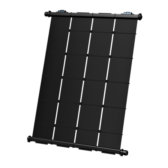
RESIDENTIAL INSTALLATION
MANUAL FOR SOLAR POOL HEATING
Before attempting installation, read these instructions and acquaint yourself with the component names.
Great care has been taken to make this an easy-to-follow procedure. A little time spent understanding
the system and its parts will assure a successful, trouble-free installation.
CAUTION: SAFETY COMES FIRST
When working on or around your roof or pool, please take care to avoid hazards such as electrical wires and
loose shingles. If you have any product or installation questions, contact your SunStar representative.
UMA Solar | © 2020
Advertisement

Summary of Contents for SunStar STR-8
- Page 1 CAUTION: SAFETY COMES FIRST When working on or around your roof or pool, please take care to avoid hazards such as electrical wires and loose shingles. If you have any product or installation questions, contact your SunStar representative. UMA Solar | © 2020...
-
Page 2: Pre-Installation Notes
SunStar durable enough to last a lifetime. However, a professional installation is very important to the overall success of a system. Installed properly, a SunStar System will be virtually maintenance free as it captures free, abundant, and reliable energy from the sun year after year. - Page 3 PRE-INSTALLATION NOTES (CONTINUED) While this manual explains how to install SunStar solar collectors properly in typical situations, it cannot possibly address all the unique or individual circumstances possible. If you have any installation questions, contact your SunStar representative for assistance.
-
Page 4: Required Tools And Materials
Concrete Anchors • Roof Sealant & Flashings NOTE: As the installer, you are responsible for exercising good judgment when installing SunStar systems to protect the long-term integrity of the collectors as well as the mounting surfaces. SUNSTAR RESIDENTIAL INSTALLATION MANUAL... - Page 5 Most residential roofs are perfectly capable of supporting solar pool heating systems and the water that runs through them. At minimum, a roof is normally built to withstand a 20 PSF live load (for people walking on a roof) and SunStar systems only exert a 1 PSF gravity load while operating.
- Page 6 ROOF ANCHOR SPACING STR-50: 12'-11 5 16 " +/- 1" STR-40: 10'-10 7 8 " +/- 1" STR-38: 9'-10 11 16 " +/- 1" STR-30: 7'-10 1 4 " +/- 1" SUNSTAR ROOF ANCHOR SPACING Fig. 1 SUNSTAR RESIDENTIAL INSTALLATION MANUAL...
- Page 7 Bank sizing is limited by the size and quantity of SunStar collectors used to achieve even flow throughout the bank. This is based on an ideal, maximum flow rate of 40 GPM to any bank of collectors.
- Page 8 4 ft. to prevent sagging or “snaking”. Piping runs should always be designed to handle thermal deformation (expansion and contraction) and pipe supports used must allow for this. Pipe supports used to secure piping to a wall should be installed every 10’ at minimum. SUNSTAR RESIDENTIAL INSTALLATION MANUAL...
- Page 9 This is especially important in areas of the country where freezing conditions occur. Like most plumping components, SunStar collectors will be damaged if water is left to freeze inside them. While SunStar collectors can handle freezing temperatures they cannot withstand, nor are they warrantied against, water freezing within them.
- Page 10 Each riser tube represents a full flow path for water from one manifold to the other. As a finished unit SunStar collectors have the ability to accept and heat a large volume of water efficiently with very little head loss.
- Page 11 C (+36) 2.92 D (+90) Thousands of BTU’s per day per panel KEY: C - Water Heating (Warm Climate) D - Space & Water Heating A - Pool Heating (Warm Climate) B - Pool Heating (Cool Climate) SUNSTAR RESIDENTIAL INSTALLATION MANUAL...
-
Page 12: Installation Kits
0-60 PSI Pressure Gauge • Pressure Test “T” Assembly REPAIR TOOL KIT In the event a collector is damaged, this kit contains everything needed to make a repair to a riser tube. • Pin Insert Tool • 1/4” Chisel SUNSTAR RESIDENTIAL INSTALLATION MANUAL... - Page 13 0-60 PSI Pressure Gauge 2-1810-007 Pin Insert Tool 2-1810-005 1-5115-028 2-1910-008 1/4” Chisel 2-1810-029 Vacuum Breaker 2-1020-007 Repair Plugs 2-2015-064 Two-Way Valve 2-3020-001 Pressure Test “T” Assembly 1-5060-021 3/8” x 4” Stainless Steel Lag Bolt 2-1810-007 2-1910-008 SUNSTAR RESIDENTIAL INSTALLATION MANUAL...
- Page 14 The valves may be placed on the supply line at least 6 ft. above the pool equipment or near the top of the system at the collectors. Failure to install vacuum relief valves can cause damage to due freezing water and/or collapsed piping. SUNSTAR RESIDENTIAL INSTALLATION MANUAL...
- Page 15 COLLECTOR LAYOUT & PLUMBING (CONTINUED) Fig. 2.1 - SINGLE ROW Fig. 2.2 - DOUBLE ROW Fig. 2.3 - SINGLE ROW SPLIT FEED SUNSTAR RESIDENTIAL INSTALLATION MANUAL...
- Page 16 END CAP END CAP END CAP END CAP END CAP RETURN FEED Fig. 6.5 - SERIES/PARALLEL FEED RETURN FEED FIGURE 5.5 Fig. 2.5 - SERIES/PARALLEL FEED SERIES/PARALLEL FEED FIGURE 5.5 SERIES/PARALLEL FEED Fig. 2.6 - DOUBLE ROW SUNSTAR RESIDENTIAL INSTALLATION MANUAL...
- Page 17 (Fig. 3-B) Place the bottom half of the plastic collector clamp under the collector manifold with the hook portion of the collector clamp facing toward the riser tubes. (Fig. 3-C) SUNSTAR RESIDENTIAL INSTALLATION MANUAL...
- Page 18 (Fig. 3-G) Insert locking clip into slots on latch. (Fig. 3-H) Use this same procedure to connect both top and bottom manifolds of the collectors. SUNSTAR RESIDENTIAL INSTALLATION MANUAL...
- Page 19 NOTE: A secure, permanent connection to the roof is important to the performance and longevity of the SunStar system. Even more important, however, is to ensure no harm is done to the structural integrity or weatherproofing of the host roof. It is highly recommended that approved roof sealants and flashings be used when making any roof penetrations.
- Page 20 Pad to the roof through the hole using a 1/4” lag bolt (Fig. 5-C). The length of the lag bolt used is based on how much embedment into the truss is required. Typically, this is 2” of embedment but the engineering plans will specify this. SUNSTAR RESIDENTIAL INSTALLATION MANUAL...
- Page 21 Once the RT-Mini is anchored into the roof attach the Mounting Pad by placing it on top of the RT-Mini with the stainless steel ¼-20 HWH bolt coming up through the hole. Fasten the mount by tightening a stainless steel 1/4-20 HWH nut onto the bolt (Fig. 6-A). SUNSTAR RESIDENTIAL INSTALLATION MANUAL...
- Page 22 Slide the bottom mounting pads onto the tracks opposite the top mounting pads. These should be aligned along the same truss Pipe supports should be used at the feed and return piping connected to the collector banks(s). Fig. 5 SUNSTAR RESIDENTIAL INSTALLATION MANUAL...
- Page 23 Concrete tile, metal, and low-slope roofing are less common but are still able to support SunStar systems. These roof types will require different strategies and mounting hardware, please contact your Heliocol representative for assistance.
- Page 24 It is recommended to wrap the bundles in an isolator (like foam pipe insulation) to prevent the tubes from directly contacting the obstruction. (Fig. 7) Fig. 7 Flexible riser tubes are snapped out of the spacer bars to go around small obstructions. SUNSTAR RESIDENTIAL INSTALLATION MANUAL...
- Page 25 Cement the PVC pipe to the CPVC Pipe Connectors as shown in Fig. 8. This should be done on both the top and bottom manifolds. If the distance between the collectors is over 4’, a pipe support should be used on both pipes to prevent sagging. SUNSTAR RESIDENTIAL INSTALLATION MANUAL...
- Page 26 COLLECTORS SunStar collectors are designed to allow for normal, vertical expansion & contraction (along the riser tubes) using the mounting hardware design for the collector. The Top Mounting Pads are designed to be a fixed position for the collector while Bottom Mounting Pads are designed to be a secure connection while allowing for the collector to change length with the ambient temperature.
- Page 27 (See Fig. 9.3). Repeat this with at the bottom manifold with Bottom Mounting Pad. Do not use this procedure more than once on any bank of collectors. USABLE STOP MECHANISM INSTALLATION SLOTS Fig. 9.3 SUNSTAR RESIDENTIAL INSTALLATION MANUAL...
- Page 28 End caps will be located on the unused corners of the collector bank(s). Attach the end caps using the PPC sets as described in the section on Connecting Collectors Together. (Fig. 11) Fig. 11 SUNSTAR RESIDENTIAL INSTALLATION MANUAL...
- Page 29 2” PVC fittings to be fit over it. Multi-purpose cement used for cementing CPVC to PVC should be used when attaching PVC fittings or pipe to the CPVC Pipe Connectors. Connect the feed and return piping using standard plumbing techniques. SUNSTAR RESIDENTIAL INSTALLATION MANUAL...
- Page 30 Continue the piping runs to the roof transition point and then down the wall to the pool equipment location. Piping should be as short as possible and properly secured to the roof and wall with pipe supports. SUNSTAR RESIDENTIAL INSTALLATION MANUAL...
- Page 31 INTERMEDIATE PLUMBING (CONTINUED) Fig. 12 SUNSTAR RESIDENTIAL INSTALLATION MANUAL...
- Page 32 Three Way Valve SENSOR Non-Positive Seal Check Valve Install before this point: • Chlorinator • Heater • Other Pool Filter Accessories Pump (optional) RETURN TO POOL (Hot) FROM POOL (Cool) NEW PLUMBING EXISTING PLUMBING Fig. 13 SUNSTAR RESIDENTIAL INSTALLATION MANUAL...
- Page 33 CONNECTING TO THE POOL EQUIPMENT (CONTINUED) Fig. 13.1 shows how a typical SunStar solar pool heating system is plumbed into existing pool plumbing. While the pool equipment may not always be configured exactly as shown it illustrates the key points for interconnecting the solar pool heating system to pool’s filtration loop.
- Page 34 A two-way isolation valve should be plumbed into the return line and should align with the isolation valve on the feed line so both may be easily accessed. SUNSTAR RESIDENTIAL INSTALLATION MANUAL...
- Page 35 The sensor probe should be in contact with the water in the pipe. Use approved sensor wiring and connect the water temperature sensor to the controller per manufacturer instructions. Follow controller manufacturer instructions to complete the installation and wiring of the controller. SUNSTAR RESIDENTIAL INSTALLATION MANUAL...
-
Page 36: Pressure Testing
Return the system to normal operation when pressure testing is complete. Be sure to open both isolation valves and replace the pressure test “T” assembly with the vacuum relief valve or plug. SUNSTAR RESIDENTIAL INSTALLATION MANUAL... - Page 37 Ensure that the system will automatically drain down when the pump is shut off or that enough manual drain valves have been installed. Verify that all pipe runs are properly supported with pipe supports. SUNSTAR RESIDENTIAL INSTALLATION MANUAL...
- Page 38 During the cooler months of the year, it is essential that the pool surface be covered at night with a “pool blanket” to maintain a comfortable water temperature. Low nighttime temperatures can lower the water temperature more than the solar can recover during the day. SUNSTAR RESIDENTIAL INSTALLATION MANUAL...
- Page 39 When the controller is in “auto” mode ensure that that all isolation valves are open. During service or winterization make sure the controller’s solar function is set to “off”, the system is drained, SUNSTAR RESIDENTIAL INSTALLATION MANUAL...
-
Page 40: Troubleshooting
C. Use the (2-2015-019) on the return line to throttle the flow back to produce more back pressure on the system. SUNSTAR RESIDENTIAL INSTALLATION MANUAL... - Page 41 Back the flow through these panels and force more water through the warmer panels. If any section of the array contains more panels than the maximum recommended on page 9 of the manual, make changes as needed to correct this. SUNSTAR RESIDENTIAL INSTALLATION MANUAL...
- Page 42 In the cooler months of the year, or on cool, partly cloudy days, temperature rise through the panels may only be 2° or 3°. Use the back of your hand to feel the water temperature difference at the pool return inlet. SUNSTAR RESIDENTIAL INSTALLATION MANUAL...
- Page 43 Do not install SunStar collectors during temperatures lower than 35 degrees. If any of the riser tube in a SunStar collector should become damaged for any reason, it can be repaired using the (RTK) repair tool kit and (138) repair plugs. The repair tool kit consists of a 1/4”...
- Page 44 Cut the riser tube to the desired length and slide it over the stub of the poly-insert for a straight, eye-pleasing fit. Repeat steps 1-4 for the other end of the riser tube. (At the opposite header.) SUNSTAR RESIDENTIAL INSTALLATION MANUAL...
- Page 45 FOR ANY QUESTIONS OR ISSUES PLEASE CONTACT YOUR UMA SALES REPRESENTATIVE 800.79.SOLAR • www.umasolar.com...
Need help?
Do you have a question about the STR-8 and is the answer not in the manual?
Questions and answers