Table of Contents
Advertisement
Quick Links
Model 391 Dante Alerting Unit
User Guide
Issue 3, December 2021
This User Guide is applicable for serial numbers
M391-00151 and later with application firmware version 2.1 and later
and STcontroller application version 3.07.01 and later
Copyright © 2021 by Studio Technologies, Inc., all rights reserved
studio-tech.com
50661-1221 Issue 3
Advertisement
Table of Contents

Related Manuals for Studio Technologies 391

Summary of Contents for Studio Technologies 391
- Page 1 Issue 3, December 2021 This User Guide is applicable for serial numbers M391-00151 and later with application firmware version 2.1 and later and STcontroller application version 3.07.01 and later Copyright © 2021 by Studio Technologies, Inc., all rights reserved studio-tech.com 50661-1221 Issue 3...
- Page 2 This page intentionally left blank.
-
Page 3: Table Of Contents
Table of Contents Revision History .................. 4 Introduction ..................5 Getting Started ..................8 Dante Configuration ................9 Model 391 Configuration ..............10 Operation .................... 14 Technical Notes ................... 17 Specifications ..................21 Appendix A–STcontroller Default Configuration Values ..... 22 Appendix B–UDP Packet Structure ............ -
Page 4: Revision History
Documents new feature which allows simultaneous call detection on channels 1 and 2. Documents expanded frequency detection range for call signals. (Was 20 kHz, now • 18-23 kHz nominal.) Issue 1, May 2018: • Initial release. Issue 3, December 2021 Model 391 User Guide Page 4 Studio Technologies, Inc. -
Page 5: Introduction
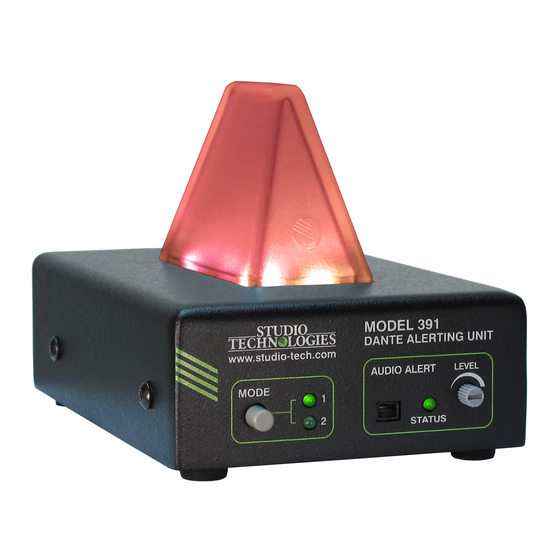
Ethernet connection with Pow- can send and receive compatible call er-over-Ethernet (PoE) capabilities for signals. Figure 1. Model 391 Dante Alerting Unit front and back views Model 391 User Guide Issue 3, December 2021 Studio Technologies, Inc. Page 5... - Page 6 The most-typical application for the Model devices are in the same room or on the 391 is to alert users that a call signal on an opposite sides of a university campus. intercom channel is active. Some techni- The Model 391’s analog line output offers...
- Page 7 Model 391’s two input (Dante receiver) audio channels A unique Model 391 feature is the line can be assigned (routed) from source de- output. Interfaced using a standard 3-pin vices using the Dante Controller software...
-
Page 8: Getting Started
1 (very low power) device. If a Firmware Updating PoE-enabled Ethernet port can’t be pro- vided by the associated Ethernet switch a The Model 391 was designed so that its low-cost PoE midspan power injector can capabilities and performance can be en- be utilized. -
Page 9: Dante Configuration
If the selected midspan power injector is mitter channel(s) on associated equipment 802.3af-compatible it should function cor- are used to supply the Model 391 with the rectly. Midspan units are available from a call signaling tones and, if applicable, the variety of sources, including many online audio signals to be sent to the unit’s line... -
Page 10: Model 391 Configuration
STcontroller be available for con- venient use in a personal computer that’s that it can control. The Model 391 unit or units will appear in the device list. Use the connected to the related LAN. - Page 11 (input) channel 2 to serve as the can disable access to Mode 2. call source. Selecting Tone Detect Ch1 & The active mode section of the Model 391 Ch2 enables tones on either or both Dan- configuration screen within STcontroller te receiver (input) channels to be recog- nized as a call source.
- Page 12 Mode 1 and cator will directly respond to an incoming Mode 2 is High. call signal. So, as an example, a very short Issue 3, December 2021 Model 391 User Guide Page 12 Studio Technologies, Inc.
- Page 13 A rotary control on the ducing a dark gray color. This seemed to front panel of the Model 391 allows the be more reasonable than trying to gen- user to select the desired output level.
-
Page 14: Operation
Model 391 and can re- with care! The default configuration for spond quickly to a visual call indication... - Page 15 The visual indicator, locat- data with another Dante device. The SYNC ed on top of the Model 391’s enclosure, LED will light red when the Model 391 is will light, starting with red then chang- not synchronized with a Dante network. It ing to green and then to blue, “cycling”...
- Page 16 Should a call signal be received by the cate that access to it has been disabled. Model 391 the LED will remain off; adjusting the trim pot will not result in any operating Visual Alert change.
-
Page 17: Technical Notes
Dante Controller software application. In the unfortunate event that a specific Model output. In other cases, audio will be present 391’s IP address is “lost” there are several on the line output only when a call signal is being received. - Page 18 Then connect the Ethernet cable. Upon applica- load a revised file into the MCU’s non- tion of PoE power the Model 391 will first volatile memory by way of a USB interface. go through its normal power-up sequence The Model 391 implements a USB host and then will display the firmware version.
- Page 19 1.2 of the application firmware connector. (m391.bin) is contained within this zip file. 4. Apply power to the Model 391 by con- Once the USB flash drive is inserted into necting to a Power-over-Ethernet (PoE) the USB interface, located on the main Ethernet source.
- Page 20 From STcontroller select mains fully mated with its associated the specific Model 391 that you wish to connectors. restore to the factory default values. Note that if a connected USB flash drive Select the Device tab and then select doesn’t have the correct file (m391.bin)
-
Page 21: Specifications
Ethernet: Neutrik etherCON RJ45 Call Activation – In-Band Tone: USB: type A receptacle (located inside Model Source: receiver channel 1, receiver channel 2, 391’s enclosure and used only for updating receiver channel 1 and 2, selectable firmware) Tone Characteristics: 18-23 kHz, nominal Dimensions (Overall): Minimum Level: –25 dBFS, nominal... -
Page 22: Appendix A-Stcontroller Default Configuration Values
Visual Alert – Action: Fast Flash Visual Alert – Color: Purple Audio Alert – Status: Off Audio Alert – Action: Continuous Audio Alert – On Delay: Follow Call Issue 3, December 2021 Model 391 User Guide Page 22 Studio Technologies, Inc. -
Page 23: Appendix B-Udp Packet Structure
Appendix B–UDP Packet Structure Supported in Application Firmware version 2.1 and later. Table 4. Model 391 Remote Settings Setting ID Setting Name Setting Values 0x19 Alerting State 0x00 - Off 0x01 - On Command Structure (without UDP header): <start> <cmd_system> <settings_len> <setting_id> <setting_val>...
Need help?
Do you have a question about the 391 and is the answer not in the manual?
Questions and answers