Table of Contents
Advertisement
Quick Links
THEORY OF OPERATION AND OPERATING PROCEDURES
OPTEC, Inc.
OPTICAL AND ELECTRONIC PRODUCTS
info@optecinc.com
http://www.optecinc.com
MODEL TCF-S
TEMPERATURE
COMPENSATING
FOCUSER
U.S. Patent No. 6,327,081
TECHNICAL MANUAL FOR
199 Smith St.
Lowell, MI 49331
U.S.A.
(888) 488-0381
Toll-Free
(616) 897-9351
(616) 897-8229
FAX
Advertisement
Table of Contents

Summary of Contents for Opitec TCF-S
- Page 1 MODEL TCF-S TEMPERATURE COMPENSATING FOCUSER U.S. Patent No. 6,327,081 TECHNICAL MANUAL FOR THEORY OF OPERATION AND OPERATING PROCEDURES OPTEC, Inc. OPTICAL AND ELECTRONIC PRODUCTS 199 Smith St. Lowell, MI 49331 U.S.A. (888) 488-0381 Toll-Free (616) 897-9351 info@optecinc.com (616) 897-8229 http://www.optecinc.com...
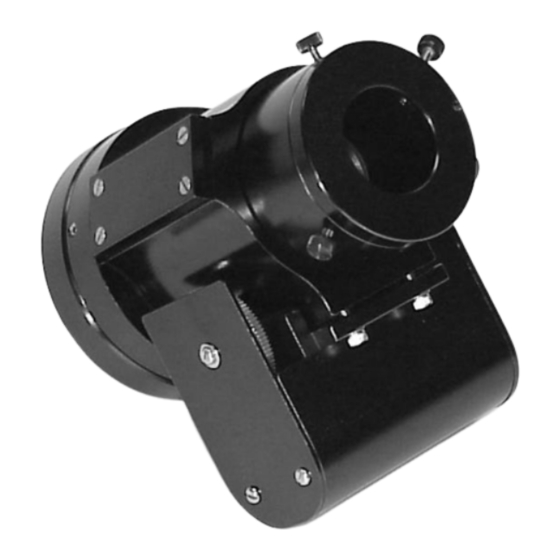
- Page 2 Figure 1-1. Model TCF-S Temperature Compensating Focuser.
-
Page 3: Table Of Contents
5.3.3 TCF-S Commands ......Troubleshooting .......... - Page 4 TCF-S Focuser Function Diagram ....... TCF-S Hand Control Layout ........
-
Page 5: Introduction
At the end of an observing session, the TCF-S focuser remembers the last temperature and position. When the unit is turned back on for a new session, the TCF-S computes a new position using the current tube temperature and moves to that position. Assuming no changes to the optical... -
Page 6: Installation
Attach telescope adapter to telescope securely without the TCF-S focuser connected. Back out the three #8 setscrews around the large diameter so that the TCF-S focuser can slip onto the telescope adapter. After rotating the TCF-S to the proper position, tighten the three setscrews evenly making sure no gap is visible between the TCF-Sand the telescope adapter. - Page 7 A control cable with 8-pin modular connector on one end and a 9-pin sub-D connector on the other is used to connect the TCF-S focuser to the control box. Lengths of cable 6, 12, 25 and 50 feet long are available from Optec. This is the same cable used with the MAXfilter/IFW and can be interchanged.
-
Page 8: Theory Of Operation
TYLE OCUSER The TCF-S focuser uses a classical Crayford design with a 2-inch ID drawtube. The drawtube is supported within in a sturdy cylinder (main body) by four ball bearing rollers and a stainless steel drive shaft mounted 120° apart. With a force of 100 to 200 pounds, the drive shaft pushes the drawtube against the ball bearing rollers, which eliminates all lateral play. -
Page 9: Focus Controller
Power is supplied to the TCF-S controller circuits through an SPDT relay of which the coil is energized by both one pole of the power switch and one of the microcontroller output ports. Thus, when power is switched off, the microcontroller will sense this condition and will keep the relay coil energized until the shutdown procedure is completed. - Page 10 Figure 3-2. TCF-S Focuser Function Diagram. An Analog Devices TMP04 serial digital output thermometer is used in the temperature probe. The modulated signal from this device is processed by the PIC microcontroller and reduced to a Centigrade scale with 0.1°C resolution.
- Page 11 When the drawtube has moved all the way IN focus toward the telescope, a zero (0) reading is shown on the DRO display. Movement of the drawtube in the opposite direction or OUT focus will stop at position 7000, which translates to a total travel distance of 0.60 inches. An integrated BiMOS unipolar driver chip is used to operate the stepper motor.
-
Page 12: Operating Procedures
ECTION OPERATING PROCEDURES Refer to Figure 4-1 for a view of the hand controller front panel. Tables 4-1 through 4-6 below explain the six most typical procedures of the TCF-S. Switch settings, functions, and errors are described. Figure 4-1. TCF-S Hand Control Layout. -
Page 13: Start-Up - Manual Mode
200 steps/sec. ERRORS: If the last position read exceeds 7000, the maximum travel length, the TCF-S controller will go to the mid position or 3500. This could only occur if the EEPROM chip has been replaced or is defective. -
Page 14: Manual Focus Operation
MANUAL FOCUS OPERATION SWITCH SETTINGS: Mode switch is in MANUAL position Learn switch is in RUN position FUNCTION: The drawtube is moved in toward the direction of the telescope when the IN pushbutton is depressed and out toward the camera when the OUT pushbutton is depressed. The LED above the pushbutton will light up when the associated button is depressed. -
Page 15: Auto Focus Operation
AUTO FOCUS OPERATION SWITCH SETTINGS: Mode switch is in AUTO-A or AUTO-B position Learn switch is in RUN position FUNCTION: Normally, focus is obtained in the MANUAL focus mode. Once achieved, the mode slide switch is moved to either AUTO-A or AUTO-B depending on the user's optical configuration. At that instant, the current position and temperature is read and stored. -
Page 16: Learn Operation
LEARN OPERATION SWITCH SETTINGS: Mode switch is in AUTO-A or AUTO-B position Learn switch is in the LEARN position FUNCTION: Step 1. At the start of the LEARN operation the word SET is displayed on the DRO. Using the IN/OUT pushbuttons, focus as in the MANUAL mode. Once exact focus is obtained with either eyepiece or CCD camera, press the PROGRAM pushbutton to store initial position and temperature. -
Page 17: Shutdown
SHUTDOWN SWITCH SETTINGS: Mode switch in any position Learn switch in RUN position FUNCTION: When the power switch is placed in the OFF position, there is a momentary delay as the internal PIC microcontroller writes the current position and temperature to the EEPROM. Once done, the unit will shut down. -
Page 18: Pc Software Control
With both the older TCF and the newer TCF-S, the IN and OUT pushbuttons can be operated remotely through the 6-pin modular interface connector. This mode of operation uses pins 2, 4 and 5 of the 6-pin modular jack on the TCF or TCF-S controller... -
Page 19: Tcf-S Rs-232 Serial Communications
The focuser can then be restarted remotely at a later time. The Advanced TTL Level Control, described in Section 5.2 above, is superceded by the RS-232 serial interface and is not available with the TCF-S without removing the on board jumper wire. -
Page 20: Communications Protocol
The RS-232 implementation used with the TCF-S is a simple 3-line interface using RX, TX, and GND. (Refer to Appendix A for wiring details.) At Optec, we use an older DOS shareware telecommunications program called PROCOMM for focuser control and testing, though any PC communication program should work. -
Page 21: Tcf-S Commands
(Focuser Auto-A Mode) Function: This command puts the TCF-S in the serial mode AUTO-A. This mode is the same as the non-serial mode AUTO-A. It even uses the same “learned” slope value. The only difference between the two is that the serial version displays the current position and temperature on the PC, hence running a little slower. - Page 22 TCF-S cannot physically move past the zero position – 0000. Warning: Entering a value such as 159, as opposed to 0159, will cause the TCF-S to move to an undesired position. Remember to right adjust all position values less than 1000.
- Page 23 However, the TCF-S cannot physically move past position 7000. Warning: Entering a value such as 159, as opposed to 0159, will cause the TCF-S to move to an undesired position. Remember to right adjust all position values less than 1000.
- Page 24 (Focuser Center) Function: This command prompts the TCF-S to move to the center position of its full range, which is 3500. FCENTR can be used to center the focuser at the beginning of any observing session. The programmer might choose to use the FCENTR command and then prompt the telescope user to focus with the coarse telescope focuser.
- Page 25 TCF-S shuts off the power to the stepper motor and to the display, which is the majority of power consumption within the TCF-S. The power LED will blink slowly to inform the user of the restful state that the TCF-S is in.
- Page 26 Command Return FREADA or FREADB “A=0nnn” or “B=0nnn” (Focuser Read Slope Command) Function: This command reads the learned slope values stored in the EEPROM for the AUTO- A or AUTO-B switch settings. Values from 0000 to 0999 can be read. The default value stored in both locations is 086, which is the slope constant for the Meade 10- inch telescope located in the Optec Observatory.
- Page 27 Similar to turning off the unit when in RUN mode (no PC) with the switch in Auto-A or B and then turning the TCF-S back on at a different time and temperature. Intended to be used with FSLEEP, which saves the current temperature and position information, and the FWAKUP command which does not automatically compensate for a change in temperature that may have occurred while in “Sleep”...
- Page 28 (Focuser Free Mode) Function: The user issues this command when the remote controlling session of the TCF-S is over. Upon executing this command the user relinquishes control back to the TCF-S controller and frees it from serial control. This command will only work if the serially controlled TCF-S is in FMMODE.
-
Page 29: Troubleshooting
ECTION TROUBLE SHOOTING A new feature for TCF-S firmware versions 2.10 and later is the reporting of error codes for certain fault conditions. These error messages are displayed on the DRO and are also reported on the serial port. Currently, the following errors are reported: ER=1 Temperature probe not connected or not working. - Page 30 the vertical position. Loads of 6 pounds and less will not slip. Call Optec if slippage is a problem for your application. 5. If the unit acts erratic when in the AUTO mode it could be the result of strong interference upon the temperature probe.
-
Page 31: Specifications
ECTION SPECIFICATIONS for TCF-S FOCUSER Type Crayford Length of focus travel 0.60" Minimum step movement 0.000085" Maximum step rate 200 steps/sec Total Backlash typically 0.0015" (18 steps) Maximum instrument load 10 lbs. Total gear reduction ratio 192:1 Focuser drive gear... -
Page 32: Wiring Diagram
Appendix A WIRING DIAGRAM... -
Page 35: Controller Board Layout
Appendix B CONTROLLER BOARD LAYOUT... -
Page 36: Original Tcf Hand Controller Circuit Board Layout
Original TCF Hand Controller Circuit Board Layout. -
Page 37: Tcf-S Hand Controller Circuit Board Layout
TCF-S Hand Controller Circuit Board Layout. - Page 38 Appendix C CONTROLLER BOARD CIRCUIT...
-
Page 40: Tcf-S Control Using Ccdsoft Version 5
TCF-S implementation. To setup CCDSoft for use with the TCF-S, open the Camera Control window by clicking Setup under the Camera menu. For “Focuser”, select Optec TCF-S. Set the correct communications port... - Page 41 Initially, leave the Automatic Temperature Compensation “Off”. The “Auto-A” and “Auto-B” option selections will place the TCF-S into either A or B mode through software. Do not adjust the slide switch on the hand controller. When you click the “Connect” button the software will send the appropriate command (FMMODE) to the TCF-S through the serial port.
Need help?
Do you have a question about the TCF-S and is the answer not in the manual?
Questions and answers