Advertisement
Quick Links
Advertisement

Related Manuals for Elettronika AUTV/1500LD


Summary of Contents for Elettronika AUTV/1500LD
- Page 1 All manuals and user guides at all-guides.com...
- Page 2 All manuals and user guides at all-guides.com...
- Page 3 All manuals and user guides at all-guides.com Section 1 - Information Contents: 1.1 Description 1.2 Technical characteristics...
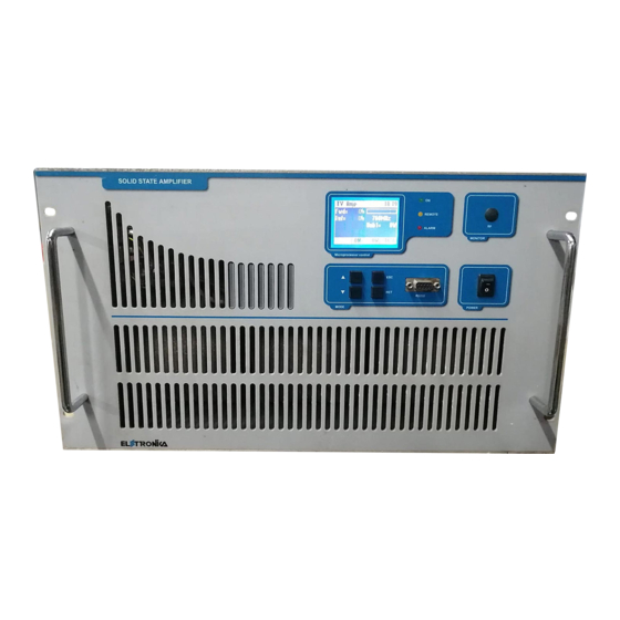
- Page 4 All manuals and user guides at all-guides.com AUTV/1500LD LDMOS - UHF TV AMPLIFIER 1.1 DESCRIPTION...
- Page 5 All manuals and user guides at all-guides.com 1.2 TECHNICAL CHARACTERISTICS GENERAL PROTECTION THR.
- Page 6 All manuals and user guides at all-guides.com...
-
Page 7: Table Of Contents
All manuals and user guides at all-guides.com Section 2 - Installation Contents: 2.1 Operating environment 2.2 Preliminary operations 2.3 Telemeasuring socket connections 2.4 RS232, RS485 and AGC socket connections 2.5 Preventive maintenance - Front panel - Rear panel... -
Page 8: Operating Environment
All manuals and user guides at all-guides.com 2.1 OPERATING ENVIRONMENT 2.2 PRELIMINARY OPERATIONS Monophase cabling Three-Phase cabling WARNING!!! FOR ELECTRICAL SAFETY REASONS AND IN ORDER TO KEEP THE APPARATUS SAFE, THE GROUND TERMINAL OF THE APPARATUS MUST BE CONNECTED TO THE EXISTING GROUND- ING SYSTEM AND NOT BY USING THE SHIELD OF THE OUTPUT COAXIAL CABLE. -
Page 9: Telemeasuring Socket Connections
All manuals and user guides at all-guides.com 2.3 TELEMEASURING SOCKET CONNECTIONS PIN N° SIGNAL TYPE IN / OUT FUNCTION 2.4 RS232, RS485 AND AGC SOCKET CONNECTIONS FUNCTIONS FUNCTIONS... -
Page 10: Preventive Maintenance
All manuals and user guides at all-guides.com PIN N° SIGNAL TYPE IN / OUT FUNCTION 2.5 PREVENTIVE MAINTENANCE... -
Page 11: Front Panel
All manuals and user guides at all-guides.com Front panel DESCRIPTION... -
Page 12: Rear Panel
All manuals and user guides at all-guides.com Rear panel DESCRIPTION... - Page 13 All manuals and user guides at all-guides.com Section 3 - Operation Contents: 3.1 Operation 3.2 Display 3.3 Menus...
- Page 14 All manuals and user guides at all-guides.com 3.1 OPERATION COLOUR MEANING MEANING WHEN BLINKING...
- Page 15 All manuals and user guides at all-guides.com 3.2 DISPLAY 3.3 MENUS...
- Page 16 All manuals and user guides at all-guides.com...
- Page 17 All manuals and user guides at all-guides.com - RF Powers - Power Supply - Log/Alarms...
- Page 18 All manuals and user guides at all-guides.com EVENT DESCRIPTION - Working Timer - Thresholds...
- Page 19 All manuals and user guides at all-guides.com - RMS/Peak - Date/Time - Display...
- Page 20 All manuals and user guides at all-guides.com - Frequency (only for some Amplifiers) - Slave Address - Remote - Interlock...
- Page 21 All manuals and user guides at all-guides.com - Firmware Release - Serial Number...
- Page 22 All manuals and user guides at all-guides.com...
- Page 23 All manuals and user guides at all-guides.com Section 4 - Diagram Contents: - Cable diagram - AUTV/1500LD Component layout - RF Section Block Diagram - MTF0070BR0 Amplifier module - Component list - SCH0192AR0 (200W UHF LDMOS Amplifier module) - SCH0223AR1 (Control board and display)
- Page 24 All manuals and user guides at all-guides.com...
- Page 25 All manuals and user guides at all-guides.com...
- Page 26 All manuals and user guides at all-guides.com...
- Page 27 All manuals and user guides at all-guides.com Component list MTF0070BR0 Amplifier module Part Name Code Description...
- Page 28 All manuals and user guides at all-guides.com...
- Page 29 All manuals and user guides at all-guides.com 200W UHF LDMOS AMPLIFIER MODULE SCH0192AR0 DESCRIPTION TECHNICAL CHARACTERISTICS...
- Page 30 All manuals and user guides at all-guides.com - Curve response graphic CALIBRATION PROCEDURE - Technical characteristics - Adjustment procedure - Adjustment points description...
- Page 31 All manuals and user guides at all-guides.com - Calibration steps Close the input and the output of the module by connecting them to a 50W W W W W dummy load Check the voltages of the polarisation circuits without assembling the transistors first: Check the work of the protections.
- Page 32 All manuals and user guides at all-guides.com...
- Page 33 All manuals and user guides at all-guides.com...
- Page 34 All manuals and user guides at all-guides.com...
- Page 35 All manuals and user guides at all-guides.com COMPONENT LIST SCH0192AR0 REF. DESCRIPTION ELETTRONIKA CODE Page 1/3...
- Page 36 All manuals and user guides at all-guides.com REF. DESCRIPTION ELETTRONIKA CODE Page 2/3 ¸ ¸...
- Page 37 All manuals and user guides at all-guides.com REF. DESCRIPTION ELETTRONIKA CODE Page 3/3...
Need help?
Do you have a question about the AUTV/1500LD and is the answer not in the manual?
Questions and answers