Table of Contents
Advertisement
Quick Links
Ham Radio Solutions
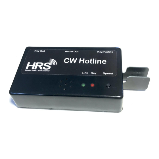
CW Hotline
Assembly Manual
Version 0.5 1-20-2022
The Ham Radio Solutions CW Hotline is a fairly simple construction project that can usually be built in
about two hours. You will need a low wattage pencil-type soldering iron with a small tip, some thin
solder, a pair of diagonal cutters and a Phillips head screwdriver. Desoldering braid may be required
to correct soldering mistakes. Be sure to wear eye protection when soldering and cutting leads.
Most parts, except for a few at the end, should be inserted into the side of the PCB with the jack
silkscreens J1, J2, J6. Unless otherwise indicated, parts should be flush with the PCB. After
inserting, turn the board over and solder the leads to the pads on the other side. It is often helpful to
just solder one lead, then ensure the component is correctly positioned before soldering the
remaining leads. Be sure to only solder the correct pads, and do not let any solder touch any other
pad or trace. Trim any excess leads with diagonal cutters after soldering each batch of components.
The checklist will be useful to ensure all components are properly assembled.
Build slowly and follow the instructions. Use the images to confirm component placement. CW
Hotline may be built with a straight key, Iambic paddles, or neither. It is recommended to drill the
case first, then use the case to aid in placing some components on the PCB.
Schematic
Advertisement
Table of Contents

Related Manuals for HRS CW Hotline

Summary of Contents for HRS CW Hotline
- Page 1 Assembly Manual Version 0.5 1-20-2022 The Ham Radio Solutions CW Hotline is a fairly simple construction project that can usually be built in about two hours. You will need a low wattage pencil-type soldering iron with a small tip, some thin solder, a pair of diagonal cutters and a Phillips head screwdriver.
- Page 2 CW Hotline includes a case, but it must have holes drilled and cut. A drilling template should be printed out at 100% size. Don’t print with “Fit to page”. Case Parts CW Hotline case Printed case drilling / cutting template 4 - M2.6 x 8mm black screws...
- Page 3 PCB Parts PCB - CW Hotline Printed Circuit Board R1, R2, R4 - 680 ohm resistors (blue-grey-brown) R3 - 10K ohm resistor (brown-black-orange) R5 - 330 ohm resistor (orange-orange-brown) C1 - 0.1uf capacitor (marked 104) Q1, Q2 - 2222A NPN transistors J1, J2, J6 - 3.5mm stereo TRS jacks...
- Page 4 Decide if the CW Hotline should be built with a straight key or Iambic paddles and follow the corresponding instructions. If it will be only used with external keys and paddles, both instructions may be disregarded. Straight Key Parts 1 Straight Key PCB arm 1 PCB wrench for #4 nuts 3 #4-40 ⅜”...
- Page 5 Paddle Parts 2 Paddle PCB arms (1 left, 1 right) 2 #4-40 3/16” screws 1 13/32” #4-40 hex standoff (10.3mm long) 1 #4-40 ⅜” screws 1 #6 steel washer (9.8mm x 1.1mm thick) 2 #4 nuts Paddle Assembly Separate the paddle arms from each other and lightly sand or file the edge where they were connected.
Need help?
Do you have a question about the CW Hotline and is the answer not in the manual?
Questions and answers