Advertisement
Quick Links
Advertisement

Summary of Contents for Majella VVCA
- Page 1 All manuals and user guides at all-guides.com VVCA DIY MANUAL Version 1.0...
- Page 2 VVCA Velocity Voltage Controlled Amplifier DIY Manual INTRODUCTION 1. The VVCA The VVCA kit is a small DIY kit. This kit is suitable for DIY’ers who have their basic soldering skills under control. The kit is designed to be as easy as possible.
- Page 3 All manuals and user guides at all-guides.com VVCA Velocity Voltage Controlled Amplifier DIY Manual 22R Resistors (2x) First we start with the 22R restistors. There are two of them (R49, R50). They are placed on the yellow markings in the figure 1.
- Page 4 All manuals and user guides at all-guides.com VVCA Velocity Voltage Controlled Amplifier DIY Manual 1K Resistors (7x) Now that the 22R resistors are soldered we with resistors. There are 7 resistors with a 1K value (R2, R12, R14, R16, R22, R25, R32).
- Page 5 All manuals and user guides at all-guides.com VVCA Velocity Voltage Controlled Amplifier DIY Manual 10K Resistors (16x) The next resistors to solder are the 10K resistors. There are 16 of them that need to be soldered (R4, R5, R6, R7, R13, R15, R18, R19, R23, R24, R27, R28, R33, R34, R37, R38).
- Page 6 All manuals and user guides at all-guides.com VVCA Velocity Voltage Controlled Amplifier DIY Manual 100K Resistors (8x) Now we are going to do the 100K resistors. There are 8 of them. (R3, R8, R17, R20, R26, R29, R36, R39) Figure 4 shows their position (yellow) on the PCB.
- Page 7 All manuals and user guides at all-guides.com VVCA Velocity Voltage Controlled Amplifier DIY Manual 220K Resistors (4x) should getting tired soldering resistors, but we are almost there! Just four of these 220K resistors. (R1, R10, R11, R31). They are yellow marked in figure 5.
- Page 8 All manuals and user guides at all-guides.com VVCA Velocity Voltage Controlled Amplifier DIY Manual 330K Resistors (4x) The last 4 resistors! These are gonna be the 330K (R9, R21, R30, R40). Figure 6 shows where they need to be placed.
- Page 9 All manuals and user guides at all-guides.com VVCA Velocity Voltage Controlled Amplifier DIY Manual IC sockets 16 pin (2x) For the LM13700’s we need to solder 2 IC sockets. There are 2 IC sockets with 16 pins PCB. Check notch...
- Page 10 All manuals and user guides at all-guides.com VVCA Velocity Voltage Controlled Amplifier DIY Manual IC sockets 14 pin (1x) Now we need to solder the 14 pin IC socket for the TL074 opamp. Check the notch for correct orientation! Figure 8:...
- Page 11 All manuals and user guides at all-guides.com VVCA Velocity Voltage Controlled Amplifier DIY Manual 100nF capacitors (6x) The are 6 capacitors on this board. Their placement is marked yellow. Figure 9: 100nF capacitors placem ent (YELLOW ) ©2018 Majella Audio...
- Page 12 All manuals and user guides at all-guides.com VVCA Velocity Voltage Controlled Amplifier DIY Manual NPN transistors 2N3906 (4x) The are 4 yellow marked PNP transistors on the PCB. We now need to solder these. Do not solder these the other way around!! Check the belly for the orientation (figure 10).
- Page 13 All manuals and user guides at all-guides.com VVCA Velocity Voltage Controlled Amplifier DIY Manual Power connector (1x) To connect this module to your eurorack system we will need to solder a 16 pin IDC connector. Notice the orientation of the...
- Page 14 3.5 mm minijack connectors (8x) Solder the 8 minijack connectors on the PCB. We use these so you can include the VVCA in your patch cable spaghetti! The placement of the jacks is marked yellow in firure 12. Figure 12:...
- Page 15 All manuals and user guides at all-guides.com VVCA Velocity Voltage Controlled Amplifier DIY Manual 22uF Capacitors (3x) Almost done! need solder electrolytic capacitors on the PCB. See figure 12 for their placement. Note their orientation, They will explode correctly placed, no...
- Page 16 All manuals and user guides at all-guides.com VVCA Velocity Voltage Controlled Amplifier DIY Manual IC placement You can turn off your soldering iron! You will only need to place the IC’s in their sockets! Note the orientation of the IC’s!.
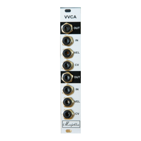
- Page 17 All manuals and user guides at all-guides.com VVCA Velocity Voltage Controlled Amplifier DIY Manual Final check + panel First check if the IC’s and the 22uF capacitors are orientated correctly. Now place the panel on to the jack connectors and put on the Hex nuts, DONE!
- Page 18 All manuals and user guides at all-guides.com VVCA Velocity Voltage Controlled Amplifier DIY Manual Bill of materials: Value Device Parts R4, R5, R6, R7, R13, R15, R18, R19, R23, R24, R27, R28, Resistor R33, R34, R37, R38 Resistor R2, R12, R14, R16, R22, R25, R32 100k Resistor R3, R8, R17, R20, R26, R29, R36, R39 100n Ceramic Capacitor C1, C2, C3, C4, C5, C6 Resistor R49, R50 220k Resistor R1, R10, R11, R31 22uF electrolytic capacitors C7, C9, C10 2N3906 PNP transistor T1, T2, T3, T4...
- Page 19 All manuals and user guides at all-guides.com VVCA Velocity Voltage Controlled Amplifier DIY Manual Thanks for your patience and soldering skills! Enjoy your VVCA! VVCA DIY Manual version 1.0 08-2018 ©2018 https://majella-audio.com support@majella-audio.com ©2018 Majella Audio...
- Page 20 All manuals and user guides at all-guides.com VVCA Velocity Voltage Controlled Amplifier DIY Manual Designed and made in Holland ©2018 Majella Audio...
Need help?
Do you have a question about the VVCA and is the answer not in the manual?
Questions and answers