Table of Contents
Advertisement
Quick Links
Advertisement
Table of Contents

Summary of Contents for Taktomat LFA
- Page 1 Linear transfer system Version 1.0 Assembly instructions 2022-03-01...
-
Page 2: Table Of Contents
Types of transport ....................................16 Assembly ......................................19 Installation position of the linear transfer system ..........................19 Mounting position of the drive unit ..............................20 Assembly of linear transfer system LFA ............................22 Initial start-up ..................................... 23 Operation ......................................24 Operating modes ....................................24 Maintenance .................................... - Page 3 Assembly instructions Troubleshooting....................................36 Disposal ......................................37 Spare and wear parts ..................................38 Annexes ......................................39 11.1 Declaration of Incorporation ................................39 Version 1.0 Linear transfer system LFA 3 / 39...
-
Page 4: About These Instructions
86554 Pöttmes Tel.: +49 (0) 8253-9965-0 Fax: +49 (0) 8253-9965-50 E-mail: info@taktomat.de Internet: http://www.taktomat.de/ Product designation Linear transfer system LFA Type Design Chain link centre distance [mm] Designation ----- Code Direction Drive unit position A = outside, I = inside, O = top, U = bottom... -
Page 5: Symbols
Overall result of the instruction Enumerations Enumerations in no strict order are indicated as follows: • Property A o Detail 1 o Detail 2 • Property B o Detail 1 o Detail 2 Version 1.0 Linear transfer system LFA 5 / 39... -
Page 6: Safety
All the warnings in these instructions have the following structure: Fig. 1: Structure of the warnings Hazard-specific symbol Hazard symbol Signal word Type and source of danger Possible consequences of non-observance Procedure for hazard prevention 6 / 39 Linear transfer system LFA Version 1.0... - Page 7 Do not carry metal parts or clocks No access with cardiac pacemaker or implanted defibrillators No access with metallic implants General warning sign Warning: Electrical voltage Warning: Magnetic field Warning: Suspended load Version 1.0 Linear transfer system LFA 7 / 39...
-
Page 8: Requirements For Personnel
Personal protective equipment is used to protect personnel from impairments to safety and health during work. Personnel must wear the personal protective equipment when performing all of the activities described in these instructions. The required personal protective equipment is indicated in the different chapters of these instructions. 8 / 39 Linear transfer system LFA Version 1.0... -
Page 9: Requirements For Incorporation Into A Complete Machine
• Maintenance work must be carried out in accordance with the maintenance schedule and the operating instructions. • All activities at the linear transfer system may only be performed by trained qualified personnel. Version 1.0 Linear transfer system LFA 9 / 39... -
Page 10: Product Description
All applications deviating from this intended use are not permitted. • Modifications to the linear transfer system must be approved by TAKTOMAT • The linear transfer system may only be operated within the defined operating parameters • The specified load on the chain links must not be exceeded •... - Page 11 [mm] H7 fitting bore [mm] 6 (2x) 6 (2x) 6 (2x) 8 (2x) diameter Thread, WC fastening [mm] M6 (2x) M6 (4x) M6 (4x) M8 (4x) Bore spacing, WC [mm] fastening Version 1.0 Linear transfer system LFA 11 / 39...
- Page 12 Assembly instructions Product description Main dimensions of the linear transfer system LFA - LFA S frame Pos. Designation Unit LFA080 LFA100 LFA125 LFA150 Centre distance [mm] see drawing see drawing see drawing see drawing Length [mm] see drawing see drawing...
-
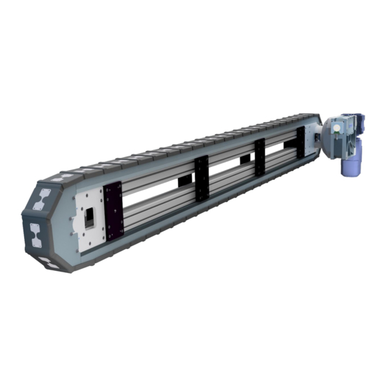
Page 13: Product Overview
Product description Product overview Fig. 3: Linear transfer system LFA without drive unit Fig. 4: Linear transfer system LFA with direct drive unit TQMSI Fig. 5: Linear transfer system driven by rotary indexing table type RT - TT Speed sensor... -
Page 14: Overload Protection (Optional)
(see Figure: Overview of the safety clutch). The limit switch is set and sealed by TAKTOMAT. To monitor the controller, the signal from the limit switch can be processed directly by a controller. When the clutch is engaged, the LED of the limit switch lights up. In the event of an overload situation, the LED goes out. -
Page 15: Transport
• Do not accept the delivery or accept it only with reservations • Note the extent of the damage on the transport documents or on the transport delivery note • Report material damage to the manufacturer immediately Version 1.0 Linear transfer system LFA 15 / 39... -
Page 16: Types Of Transport
Fig. 7: Linear transfer system in vertical position with slings Slings (e.g. chains, straps) Linear transfer system Wooden frame Transport foot Fig. 8: Specification of inclination angle and pick-up points for industrial trucks 16 / 39 Linear transfer system LFA Version 1.0... - Page 17 Only transport with industrial trucks at the marked pick-up points (see figure below). Fig. 9: Linear transfer system with slings Linear transfer system Sling (see table for thread) Slings (e.g. chains, straps, attachment eyes, Wooden frame eyebolts) Version 1.0 Linear transfer system LFA 17 / 39...
- Page 18 VLBG 1.5 t LFA125S LFA150 - < 3000 VLBG 2.5 t LFA150S ≥ 4 LFA150 - > 3000-6000 VLBG 2.5 t LFA150S ≥ 8 LFA150 - > 6000 VLBG 2.5 t LFA150S 18 / 39 Linear transfer system LFA Version 1.0...
-
Page 19: Assembly
NOTICE The installation and mounting positions are specified according to the project planning. They may not be changed without consulting TAKTOMAT • Only install the linear transfer system in the specified position One of the installation positions listed below is specified during project planning. The linear transfer system must be installed in the specified installation position. -
Page 20: Mounting Position Of The Drive Unit
In addition, the drive unit is mounted in one of the mounting positions shown below. Fig. 13: Mounting positions of the vertical linear transfer system Mounting position O (top) Mounting position I (inside) Mounting position U (bottom) Mounting position A (outside) 20 / 39 Linear transfer system LFA Version 1.0... - Page 21 In addition, the drive unit is mounted in one of the mounting positions shown below. Fig. 15: Mounting positions of the vertical linear transfer system Mounting position A (outside) Mounting position I (inside) Mounting position R (right) Mounting position L (left) Version 1.0 Linear transfer system LFA 21 / 39...
-
Page 22: Assembly Of Linear Transfer System Lfa
For installation in a system, TAKTOMAT recommends fastening the LFA linear transfer system with brackets (3). The brackets are firmly attached to the intermediate plates (1) with screws (2). -
Page 23: Initial Start-Up
For attachments / workpiece carriers (WC) on the chain link, observe the following: • Maximum mass moved (according to TAKTOMAT project planning) • Minimum time until positioning (according to TAKTOMAT project planning) • Maximum overhang (tilting moment) (according to TAKTOMAT project planning) •... -
Page 24: Operation
The emergency stop immediately stops the movement of the linear transfer system. The resultant load that is built up puts a strain on the linear transfer system. The emergency stop should therefore only be used in emergency situations. 24 / 39 Linear transfer system LFA Version 1.0... -
Page 25: Maintenance
Spare parts must comply with the technical requirements specified by the manufacturer. This is always ensured if genuine spare parts are used. Environmental protection Remove leaking or excess grease from lubrication points and dispose of it in accordance with the applicable local regulations. Version 1.0 Linear transfer system LFA 25 / 39... - Page 26 After cleaning, check all supply lines to ensure that they do not leak, that no connections have come loose, and that they show no signs of abrasion or damage. Immediately rectify any defects. 26 / 39 Linear transfer system LFA Version 1.0...
-
Page 27: Checking And Adjusting The Chain Tension
5. Turn each deep groove ball bearing (2) (4 per chain link (5)) alternately around the circumference of the deflection wheel. If all deep groove ball bearings can be turned equally tightly, the chain tension is correct. Version 1.0 Linear transfer system LFA 27 / 39... - Page 28 7. Repeat step 4. If the pretension of the deep groove ball bearings (2) is not correct, start again at step 1. 8. Secure the hexagon bolt (1) against turning and tighten the hexagon nut (10). The chain tension is correctly adjusted. 28 / 39 Linear transfer system LFA Version 1.0...
-
Page 29: Referencing The Chain Position
Referencing is carried out by means of reference bores in the drive unit. These bores are located at the top and bottom of the drive side of the linear transfer system. The referencing can be performed at either of the two bores as desired. Fig. 19: Position of the reference bores Version 1.0 Linear transfer system LFA 29 / 39... - Page 30 6. Remove the cylindrical pin with female thread (1) using a suitable tool (slide hammer / pin extractor). The chain is referenced. The linear transfer system is ready for operation. 30 / 39 Linear transfer system LFA Version 1.0...
-
Page 31: Separating And Joining The Chain
Remove the Seeger ring (3), the deep groove ball bearing (6) and the grub screw (4) on the axle (5). 4. Knock out the axle (5) (top and bottom). Catch any chain sections if necessary. Fig. 23: Separating the chain strand Version 1.0 Linear transfer system LFA 31 / 39... - Page 32 5. Release the separation points (7) in the aluminium profile. 6. Pull apart the linear transfer system LFA. 7. Reassemble the components in reverse order. Fig. 24: Chain and linear transfer system LFA separated 32 / 39 Linear transfer system LFA...
-
Page 33: Replacing The Limit Switch (Optional)
In the event of overload, the pressure disc (1) of the clutch (2) shifts in the axial direction to the right (see figure: Detailed view of the drive unit clutch). The clutch (2) disengages and disconnects the drive unit from the linear transfer system. Version 1.0 Linear transfer system LFA 33 / 39... - Page 34 8. Use a torque wrench to tighten the lock nut with a maximum of 6. Nm. 9. Engage the clutch. The LED on the limit switch (3) will then light up. 34 / 39 Linear transfer system LFA Version 1.0...
- Page 35 The high signal of the limit Connect another limit switch of the Limit switch is defective switch continues to come with same type the clutch disengaged Version 1.0 Linear transfer system LFA 35 / 39...
-
Page 36: Troubleshooting
• Remove blockage Sensor transmits no signal actuated • Cable defective • Check cable and replace if necessary • Sensor defective • Replace sensor • No supply voltage • Check voltage 36 / 39 Linear transfer system LFA Version 1.0... -
Page 37: Disposal
1. Disconnect the system from all power supplies and secure it against being switched on again. 2. Wait 15 minutes until all live components are completely discharged. 3. Disassemble and dispose of assemblies and components in accordance with local environmental regulations. Version 1.0 Linear transfer system LFA 37 / 39... -
Page 38: Spare And Wear Parts
• Check spare parts for faults or defects prior to installation Spare and wear parts are always order-specific. A corresponding spare and wear parts list is available from TAKTOMAT on request. When ordering spare parts, always specify the serial number. The serial number is located on the nameplate. -
Page 39: Annexes
Assembly instructions Annexes Annexes 11.1 Declaration of Incorporation Version 1.0 Linear transfer system LFA 39 / 39...
Need help?
Do you have a question about the LFA and is the answer not in the manual?
Questions and answers