Advertisement
Quick Links
Advertisement

Subscribe to Our Youtube Channel
Related Manuals for SRC SRC-PRO V2

Summary of Contents for SRC SRC-PRO V2
- Page 1 ISTRUZIONI DI MONTAGGIO ASSEMBLY INSTRUCTION SRC-PRO V2...
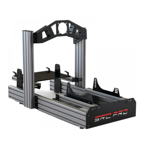
- Page 2 1 – DIMENSIONI DELLA POSTAZIONE 1 – RIG DIMENSION 775mm...
-
Page 3: Contenuto Della Confezione
2 – CONTENUTO DELLA CONFEZIONE 2 – CONTENT OF THE PACK... -
Page 4: Prima Di Iniziare
3 – PRIMA DI INIZIARE 3 – BEFORE STARTING 3.1 STRUMENTI NECESSARI .1 USEFULL TOOLS 3.2 ZONA DI MONTAGGIO E OPERAZIONI 3.2 MOUNTING AREA AND PRELIMINARY PRELIMINARI OPERATIONS Assicurati di avere lo spazio necessario per il montaggio. Il Make sure you have the necessary assembly space. The prodotto deve essere montata su una superficie piana e solida. - Page 5 4 – MONTAGGIO 4 – MOUNTING FASE 1 STEP 1 Assemblare 2 angolari ALL135 come indicato in fig.1. Assicurati Assemble 2 ALL135 angular brackets as shown in pic.1. Make che le viti non escano da tasselli per rendere più semplici i sure the screws do not exit from the sliding dowel to make the passaggi successivi.
- Page 6 FASE 2 STEP 2 Prendere il profilato B e inserire alle estremità 2 angolari ALL 135S Get the B extrusion bar and insert at the ends of it N.2 ALL 135S come indicato in fig.2. Non stringere completamente le viti per angular brackets as shown in pic.2.
- Page 7 FASE 3 STEP 3 Posizionare i 2 profilati A ad una distanza di circa 500 mm. Place the 2 A extrusion bars with a center-to-center of about Inserire il profilato B così come indicato in fig.3 e farlo scorrere 500 mm. Insert the B bar as shown in pic.3 and slide carefully the con attenzione nelle cave.
- Page 8 FASE 4 STEP 4 Istruzioni di montaggio del kit piedini in gomma. Assembly instruction of the Rubber Feet Kit. Posizionare la struttura su un fianco per facilitare il montaggio. Place the structure on its side to facilitate the mounting of the kit.
- Page 9 FASE 5 STEP 5 Posizionare i tasselli come indicato in fig.6 e avvitare i piedini in Place the dowels as indicated in pic 6 and screw the rubber gomma come indicato in fig.7 utilizzando 4 viti M6x25 TR. feet as shown in pic.7 using 4 M6x25 TR screws. Figura 6 Figura 7...
- Page 10 FASE 6 STEP 6 Inserire 2 tasselli 13x13M nella cava superiore del profilato B Insert 2 13x13M dowels in the B bar as shown in pic.8. (fig.8). Figura 8 FASE 7 STEP 7 Assemblare 2 angolari ALL 45S come indicato in fig.7. Assicurati Assemble 2 ALL 45S angular brackets as shown in pic.7.
- Page 11 FASE 8 STEP 8 Inserire 1 angolare ALL 45S per ogni profilato L (fig.10). Insert 1 ALL 45S previously assembled in each L extrusion bar Posizionare i profilati L sulla struttura e fissarli ai tasselli 13x13M (pic.10). Place the L bars on the rig and fix them to the 13x13M precedentemente inseriti utilizzando 2 viti M8x16TS (fig.11).
- Page 12 FASE 10a STEP 10a Istruzioni per il montaggio del kit sedile. Assembly instruction of the Seat Kit. SEDILI CON FISSAGGIO LATERALE FOR LATERAL FIXING SYSTEM SEAT Montare le staffe utilizzando 4 viti M8x20TB e 4 tasselli 13x25S Assemble the seat support using 4 M8x20 TB screws and 4 13x25S (fig.13-A).
- Page 13 FASE 10b STEP 10b Istruzioni per il montaggio del kit sedile. Assembly instruction of the Seat Kit. SEDILI CON FISSAGGIO inferiore FOR LOWER FIXING SYSTEM SEAT Montare le staffe utilizzando 4 viti M8x20TB e 4 tasselli 13x25S Assemble the seat support using 4 M8x20TB screws and 4 13x25S (fig.13-B).
- Page 14 FASE 11 STEP 11 Prendere una piastra e inserire 4 viti M8x16 TS nei fori centrali Take 1 plate and insert 4 M8x16 TS screws in the central holes as come indicato in fig.15. Girare la piastra e inserire 4 tasselli shown in pic.15.
- Page 15 FASE 12 STEP 12 Posizionare la piastra su un piano orizzontale con i tasselli rivolti Place the plate on a horizontale surface with the dowels facing verso l’alto. Far scivolare il profilato D come indicato in fig.17. Slide 1 D extrusion bar on the plate as shown in pic.17. Figura 17...
- Page 16 FASE 13 STEP 13 Posizionare la piastra e il profilato in verticale e stringere le viti Place the plate and the bar in vertical position and tighten the facendo attenzione che la piastra e il profilato siano a contatto screws being carefull that both the plate and bar are in contact con la superfice di appoggio (fig.18).
- Page 17 FASE 14 STEP 14 Inserire 6 viti M8x20 TB nei fori, girare la piastra e inserire 6 tasselli Insert 6 M8x20 TB screws in the holes, turn the plate and place 6 13x25S come indicato in fig.19. 13X25S sliding dowels as shown in pic.19. Figura 19...
- Page 18 FASE 15 STEP 15 Inserire i tasselli della piastra nella cave del profilato A Insert the dowels of the plate in the rails of the A from the front dall’estremità frontale della struttura come indicato in fig.20. Far side of the rig as shown in pic.20. Slide the plate up to 450 mm scivolare la piastra a 450 mm circa come indicato in fig.21.
- Page 19 FASE 16 STEP 16 Ripetere le fasi 11, 12, 13, 14 e 15 per montare l’altro supporto Repeat the steps 11, 12, 13, 14 and 15 to assembly the other verticale (fig.22). vertical support (pic.22). Figura 22...
- Page 20 4 tasselli 13x25S (fig.23). Inserire le 2 piastre nelle cave dowels (pic.23). Insert the 2 plates in the rails of the bars with the dei profilati con il logo SRC rivolto verso l’esterno (fig.24). SRC logo facing outwards (pic.24).
- Page 21 FASE 19 STEP 19 Inserire 2 viti M8x20TR nelle asole di ciascuna piastra montanti Insert 2 M8x20TR screws in the slots of the plates using 2 13x25S utilizzando 2 tasselli 13x25S (fig.27). Inserire i 2 profilati F con la dowels (pic.27). Insert the 2 F bars with the pedals plate facing piastra pedaliera rivolta verso l’esterno (fig.28).
- Page 22 FASE 20 STEP 20 Inserire 4 leve M8x25 nei fori della piastra di appoggio della Insert 4 M8x25 joints in the holes of the pedal base plate using 4 pedaliera utilizzando 4 tasselli 13x25S (fig.29). Far scorrere la 13x25S douwels (pic.29). Slide the plate on the F bars (pic.30) piastra sui profilati F (fig.30) e stringere le viti (fig.31).
- Page 23 FASE 21 STEP 21 Se fosse necessario posizionare la pedaliera più in alto, inserire If you need to place the pedals in a higher position, insert 1 un tassello a molla 13x13M nella cava corrispondente del 13x13M spring dowels in a rail of the D bar, insert the aluminium profilato D, inserire il cilindro in alluminio e fissarlo utilizzando 1 cylinder and fix it using 1 M8x70 screw (pic.33).
- Page 24 FASE 22 STEP 22 Ora puoi montare sulla postazione le tue periferiche e regolare Now you can mount your devices and adjust the rig following la postazione secondo le tue necessità. Quando avrai trovato la your needs. Once you have found your ideal configuration, tua configurazione ideale, potrai inserire i tappi per i profilati e le place the caps on the brackets and on the bars as shown in squadrette come indicato in fig.34.
- Page 25 GRAZIE PER AVER ACQUISTATO UN PRODOTTO SRC! THANK YOU TO PURCHASE A SRC PRODUCT! Per qualsiasi informazione o assistenza scrivi a support@simracecomponents.com. For any information or assistance contact us at support@simracecomponents.com. Seguici su www.simracecomponents.com Follow us...
Need help?
Do you have a question about the SRC-PRO V2 and is the answer not in the manual?
Questions and answers