
Related Manuals for exemys RME1-TC


Summary of Contents for exemys RME1-TC
- Page 1 RME1-TC User’s Manual - Thermocouple Acquisition Module Exemys www.exemys.com Rev. 1 Page 1...
- Page 2 RME1-TC User’s Manual - Thermocouple Acquisition Module Exemys Exemys Products are in constant evolution to meet our customers´ needs. For that reason, specifications and capabilities are subject to change without previous notice. Updated information can be found at www.exemys.com Copyright © Exemys, 2007. All rights reserved Rev.
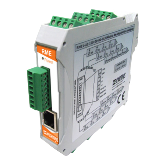
- Page 3 RME1-TC User’s Manual - Thermocouple Acquisition Module Exemys Index INTRODUCTION 1.1 About this manual _______________________________________________________ 6 1.1.1 Purpose of this manual 1.1.2 Conventions, terms and acronyms 1.2 Product General Description________________________________________________ 7 1.3 RME1-TC models codification_______________________________________________ 7 INSTALLATION 2.1 Connectors general diagram _______________________________________________ 9 2.2 Power connection _______________________________________________________ 9...
-
Page 4: Table Of Contents
Figure 7 - Serial cable for configuration serial terminal Figure 8 - Straight-through cable scheme Figure 9 - RJ45 connector Figure 10 - RME1-TC analog inputs in each channel arrangement Figure 11 - A thermocouple connection Figure 12 - Leds indicators Figure 13 - Exemys device locator Figure 15 - Enter the IP address in the Web browser. - Page 5 RME1-TC User’s Manual - Thermocouple Acquisition Module Exemys Figure 18 - Inputs configuration Figure 19 - Alarms configuration Figure 20 - User´s monitor configuration Figure 21 - Advanced options Figure 22 - Csv analog example Figure 23 - SNMP configuration Figure 24 - Administrator’s monitor...
-
Page 6: Table 1 - Acronyms
RME1-TC User’s Manual - Thermocouple Acquisition Module Exemys Chapter Chapter Introduction 2.1 About this manual 2.1.1 Purpose of this manual The purpose of this manual is to provide instructions to install and operate the Thermocouple Acquis ion Module RME1-TC in a quick and easy way. -
Page 7: Figure 1 - Usage General Diagram
An IP address. aaa.bbb.ccc.ddd 2.2 Product General Description The RME1-TC is a complete interface for your thermocouples. It allows monitoring and supervising in a remote way up to 8 thermocouples. The information can be read by any of the four RME1 -TC work modes. -
Page 8: Figure 2 - Models Codification Details
RME1-TC User’s Manual - Thermocouple Acquisition Module Exemys RME1-TC-100-00-80-IA3 RS232 Serial Ports RS485 Serial Ports Rs422 Serial Ports Case Digital Inputs Analog Outputs Digital Outputs Analog Inputs Figure 2 - Models codification details www.exemys.com Rev. 1 Page 8... -
Page 9: Figure 3 - Connectors General Diagram
2.2 Power connection Picture 4 shows the power input connection. It is found in the first two terminals called Vin (+) and GND (-).The RME1-TC power connection has polarity and it accepts the range of 10 to 30 Vdc. www.exemys.com Rev. -
Page 10: Figure 4 - Power Connection Diagram
2.3 RS-232 serial port connection (only for configuration) The RME1-TC has one configuration serial port whose connection terminals are shown in the picture below. The configuration serial port is available for all the RME1-TC models. The same picture also shows where the Ethernet connector is placed. -
Page 11: Figure 6 - Serial Rs-232 Terminal Detail
RxD 2 TxD 3 GND 5 GND 8 Figure 7 - Serial cable for configuration serial terminal 2.4 Ethernet connection The RJ45 connector is for Ethernet connection. This connection is essential for the RME1-TC to work. www.exemys.com Rev. 1 Page 11... -
Page 12: Figure 8 - Straight-Through Cable Scheme
RME1-TC User’s Manual - Thermocouple Acquisition Module Exemys 2.4.1 Hub or Switch connection To connect the RME1-TC to Ethernet through a Hub or Switch, it is necessary to use a straight- through UTP network cable. Rx+ (1) Rx+ (1) Rx- (2) -
Page 13: Figure 10 - Rme1-Tc Analog Inputs In Each Channel Arrangement
Detail of channel no connecting NC ( FRONTAL VIEW NC (no connecting) CH5 CH6 CH7 Figure 10 - RME1-TC analog inputs in each channel arrangement TC0+ Channel 0 TC0- Thermocouples J,K,T,R,N,E,S Figure 11 - A thermocouple connection 2.6 Indicator Leds... -
Page 14: Figure 12 - Leds Indicators
Figure 12 - Leds indicators Table 4 - Indicator Leds Yellow Led Green Led Description RME1-TC is searching for a DHCP server in It is steady on Do not care the network. RME1-TC is starting. It is ½ second on and ½ second off. - Page 15 RME1-TC tries to negotiate an IP address with the DHCP server for a maximum period of 10 seconds. If the DHCP fails to answer in that period, the RME1-TC will show an error code by means of its indicator LEDs (See Table 4) and will try to establish connection with the DHCP server 60 seconds later.
-
Page 16: Figure 13 - Exemys Device Locator
• Select the device in the grid and click on the “Properties” button, or open the “Actions” menu and select the “Properties” command. You will see the Properties dialog box. • All Exemys devices provide a Remote Configuration Password. This password is used by the Web configuration page and remote command Console in the device. - Page 17 . Once the port is opened with the serial 9600,8,N,1 parameters configuration, the RME1-TC must turn on and type ”cfg” with the Hyperterminal before 7 seconds have elapsed from the moment it is turned on. You will get access of the configuration through serial port and will see : www.exemys.com...
-
Page 18: Figure 15 - Enter The Ip Address In The Web Browser
- Telnet console configuration (See Appendix D) - Serial console configuration (See Appendix D) Once the RME1-TC has a valid IP address you may access the web page to configure the rest of the parameters. 1. If your web navigator is configured to search for a Proxy server, disable that option. -
Page 19: Figure 16 - Enter The Host Name In The Web Browser
As it is shown in the figure above, the name of the analog module in the manufacturer’s configuration is NBNS: RME1-TC (last digits from Mac address) , and this name can be changed using the Exemys Device Locator by means of the Host name parameter, in properties. -
Page 20: Figure 17 - Net Configuration
Figure 18 - Inputs configuration 3.2.3 Alarms configuration The RME1-tc has two alarms for each input, a low one and a high one. You will be able to enable, disable and modify the set point for each one. IMPORTANT: Alarms are taken upon temperature values multiplied by 10 www.exemys.com... - Page 21 RME1-TC User’s Manual - Thermocouple Acquisition Module Exemys Figure 19 - Alarms configuration 3.2.4 Monitor In the monitor web page you can configure the user´s monitor page. This configuration consists in selecting the inputs you want to visualize and the name you want to assign to each input.
- Page 22 RME1-TC User’s Manual - Thermocouple Acquisition Module Exemys IMPORTANT: Each name can be formed for up to 16 characters. 3.2.5 Advanced configuration Among the possible advanced configurations you can find: • Change password: It allows changing manufacturer’s default password for another one Note: The name of the user must be “admin”...
- Page 23 - Web page (HTTP) 4.1 TCP Modbus operation In the RME1-TC each one of the thermocouple inputs, matches with one Modbus TCP Holding Register. This way , once the communication has been established, data is moved in a transparent way from the PT100 inputs to the corresponding Modbus TCP address.
-
Page 24: Table 5 - Modbus Registers
If you want to make an automatic data acquisition through other query method under HTTP, the RME1-TC has 3 web pages where you can get, in plain text format delimited by commas, its analog inputs status. he available information in these pages is as follows: •... - Page 25 To make an automatic information acquisition, the RME1-TC has a web page in which all configuration and status information is available in XML format. The name of this page is rme1-tc.xml (this page is within RME1-PT). Any time you access to this page you can get the following updated information from the analog module <RME1-TC>...
- Page 26 RME1-TC User’s Manual - Thermocouple Acquisition Module Exemys <HOSTNAME>RME1-TC-30104B</HOSTNAME> </NETWORK> <AINPUTS> <AINPUTSTABLE> <ENTRY-0> <NUMBER>0</NUMBER> <NAME>Entrada 0</NAME> <AVALUE>000.0</AVALUE> <ATYPE>TC-K</ATYPE> <ALARM>LOW</ALARM> </ENTRY-0> <ENTRY-1> <NUMBER>1</NUMBER> <NAME>Entrada 1</NAME> <AVALUE>000.0</AVALUE> <ATYPE>TC-K</ATYPE> <ALARM>LOW</ALARM> </ENTRY-1> <ENTRY-2> <NUMBER>2</NUMBER> <NAME>Entrada 2</NAME> <AVALUE>000.0</AVALUE> <ATYPE>TC-K</ATYPE> <ALARM>LOW</ALARM> </ENTRY-2> <ENTRY-3> <NUMBER>3</NUMBER> <NAME>Entrada 3</NAME>...
- Page 27 RME1-TC User’s Manual - Thermocouple Acquisition Module Exemys The RME1-TC also includes the file crossdomain.xml. This a reading politics file that allows reading the rme1-tc.xml from any domain in Action Script applications. 4.3 SNMP mode operation 4.3.1 Introduction The RME1-TC supports the SNMP supervision protocol. The RME1-TC works as a SNMP agent, this means that it answers queries under this protocol and it is also able to generate unsolicited messages (Traps) for certain events / alarms notification.
-
Page 28: Table 6 - Oid Values
When an input temperature value reaches an alarm set point configured for that input, it moves its status from normal to alarm. The RME1-TC notifies this event by sending a SNMP trap to the manager’s IP address configured as Manager. -
Page 29: Web Page Operation Mode (Http)
, Type 2 4.4 Web page operation mode (HTTP) The RME1-TC web interface allows two different types of monitor. In the administrator’s monitor it is possible to visualize the assigned name, the temperature value and the alarm status for each input. This page is protected by password. - Page 30 • XML page: RME1-TC has one xml page where you can get information about device’s configuration and status. • User’s manual: This link goes to the RME1-TC user’s manual in the Exemys web site. • Exemys web site: This link goes to the Exemys web site where you can get updated information for this and other Exemys products.
-
Page 31: A Mounting Of The Device On Din Rail
Push the RME1-TC firmly until you hear a click at the moment of fastening the module on the DIN rail. - Page 32 RME1-TC User’s Manual - Thermocouple Acquisition Module Exemys DEVICE LATERAL VIEW DIN Rail DIN Rail Figure 28 - Device Disassembly www.exemys.com Rev. 1 Page 32...
-
Page 33: Original Manufacturer´s Configuration
RME1-TC User’s Manual - Thermocouple Acquisition Module Exemys Appendix Appendix B. ORIGINAL MANUFACTURER´S CONFIGURATION Table 8 - Original manufacturer´s configuration Menu Parameter Value Hostname RME1-TC-XXXXXX (*) Network IP Address 0.0.0.0 (DHCP enable) Netmask 0.0.0.0 Gateway 0.0.0.0 Type of thermocouple Thermocouple Type K... -
Page 34: Technical Specifications
RME1-TC User’s Manual - Thermocouple Acquisition Module Exemys Appendix Appendix C. Technical specifications • Resolution: 0,1°C • Input type and quantity 8 Inputs for thermocouples J, K, T, R, N, E • Protocols: TCP / IP, ICMP, ARP, DHCP, NBNS, HTTP. -
Page 35: Configuration Console
Through TCP/IP Ethernet Port (TELNET) The RME1-TC supplies a command console to allow configuration by TCP in the port 23. The device will only administer one TCP connection in this port, preventing the device to be configured in simultaneous consoles. -
Page 36: Password Command
RME1-TC User’s Manual - Thermocouple Acquisition Module Exemys D.2. Commands All commands can be entered in capital or lower case letters. D.2.1 Password Command The TCP configuration console and Web configuration interface are protected with a password. The device’s administrator can assign a password to the device providing a secure method to access the RME1-TC configuration. -
Page 37: Factreset Command
0.0.0.0 enables DHCP Gateway D.2.4. FACTRESET Command At any time,the RME1-TC administrator can reset the original manufacturer’s configuration. This option can be executed through the command console with the FACTRESET command, this way you will have the original configuration. -
Page 38: Aalarm Command
RME1-TC User’s Manual - Thermocouple Acquisition Module Exemys Table 15 - ALIST command Command Description Lists all the analog inputs status. ALIST D.2.8 AALARM Command With this command you can enable or disable Low and High alarms and configure its set points. -
Page 39: Snmpmanager1 Command
RME1-TC User’s Manual - Thermocouple Acquisition Module Exemys D.2.12 SNMPMANAGER1 command With this command you can configure the SNMP manager 1 IP address. It is possible to enter the 0.0.0.0 IP address and it means that the manager does not exist... -
Page 40: Other Configuration Commands
RME1-TC User’s Manual - Thermocouple Acquisition Module Exemys Table 24 - SNMPTRAPCN command Command Description Configures the SNMP trap community SNMPTRAPCN:com D.2.17. Other Configuration commands The following commands allow asking for help, listing the configuration and saving the configuration in device’s memory. -
Page 41: Table 26 - Telnet Commands
RME1-TC User’s Manual - Thermocouple Acquisition Module Exemys Table 26 - Telnet commands Command: Syntax Description Ends configuration Lists configuration commands HELP Shows configuration values LIST IP configuration NETCONFIG:ip_addr,netmask,gateway Netconfig:0.0.0.0, 0.0.0.0, 0.0.0.0 Enables DHCP service Device’s name HOSTNAME:name Device’s password (XXXXXX is the password to configure) -
Page 42: Arp Method To Configure Ip Address
Exemys E. ARP method to configure IP address In case you want the RME1-TC to have a static IP address (no DHCP service), you can assign it to the device using the ARP method. If RME1-TC receives, within the first 7 seconds after power on, an ICMP packet (ping) it will get that packet destination address.
Need help?
Do you have a question about the RME1-TC and is the answer not in the manual?
Questions and answers