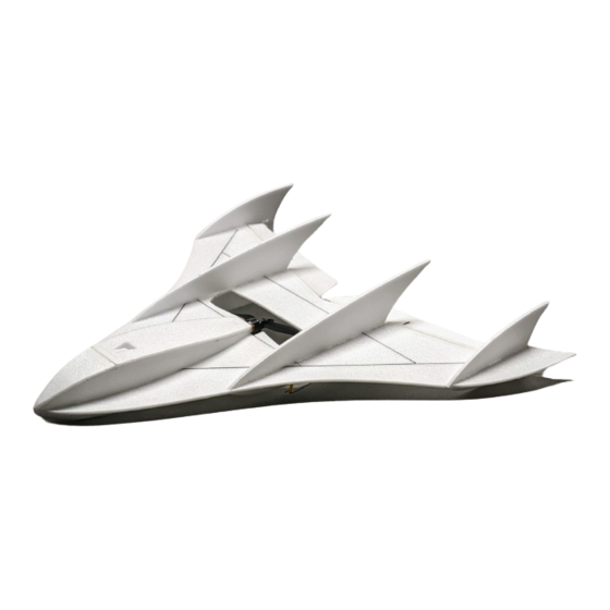

Summary of Contents for Foam-Flite Mini BluFO
- Page 1 Mini BluFO Suggested Gear: 10 gram 2700 to 2900 Kv motor Designed By 4.5 x 4.0 propeller or similar 6 amp ESC Joel Dirnberger 350 mAh 2S lipo 2 to 4 gram Servos (2) Revised: September 2020...
- Page 2 Parts Sheet Layouts There are three parts sheets included in the kit. Inspect the parts for any issues before starting the build. Please contact us with any concerns. Cut the pieces out with a sharp X-acto blade. Only cut the parts as you need them so you do not misplace parts.
- Page 3 Spar Lengths: A = 6.1” B = 10.7” Assemble the wing platform from parts C = 11.2” W1 through W5 and four 3mm x 0.5 mm spars Bevel the leading edges of the elevons (E1) and hinge them to the wing platform...
- Page 4 Attach the dorsal fins (D1) to the top of the wing platform using the tabs and slots for alignment. Gently bend the upper fuselage sides (F1) to match the curved slots in the wing platform. Attach them to the top of the wing platform along with former F2, using F2 to help keep the sides perpendicular to the wing.
- Page 5 Gently bend H1 to fit the curve of the upper fuselage, then attach it to the fuselage using a tape hinge between H1 and F3. Drill an 1/8” hole through H1 and F4 then glue the hatch magnets into the holes. make sure to orient the magnets so they hold the hatch closed.
- Page 6 Gently bend the lower fuselage sides (B1) to match the curved slots in the wing platform. Attach them to the bottom of the wing platform along with former B2, using B2 to help keep the sides perpendicular to the wing. Sand the lower edges of B1 and B2 to square them up in preparation for attachment of B3.
- Page 7 Attach the horizontal tip fins to the vertical tip fins using the tabs and slots for alignment. Trim and sand the rear of the fuselage to provide a flat gluing surface for the firewall. Trim and sand the rear edge of the hatch so that it will clear the firewall Firewall when opening.
- Page 8 To make additional room inside the fuselage for the receiver, ESC & battery, portions of the wing platform may be cut away. Remove as needed Suggested starting CG 7.1” back from the nose. 7.1” Suggested starting throws: (Measured at the control horn) Aileron 0.2"...
Need help?
Do you have a question about the Mini BluFO and is the answer not in the manual?
Questions and answers