Table of Contents
Advertisement
Quick Links
Advertisement
Table of Contents

Related Manuals for CUAV LTE-LINK SE


Summary of Contents for CUAV LTE-LINK SE
- Page 1 LTE-LINK SE User's Guide v2.0.0 CUAV TECH INC.,LTD...
-
Page 2: Table Of Contents
4.2.5 SIM card access and network service connection debugging......13 5 Use and operation........................14 5.1 Preparation before use..................... 14 5.2 Boot interface and system version information............... 14 5.3 CUAV cloud server connection..................15 5.3.1 Effective SIM card insertion detection..............15 5.3.2 Register SIM card network...................15... - Page 3 5.3.3 Connect to the public network................16 5.3.4 Public network connection is successful.............. 16 5.3.5 Synchronize network time to device..............16 5.3.6 Request to connect to CUAV Cloud Server............17 5.3.7 Successfully connected to the server..............17 5.4 Device binding and unbinding..................18 5.4.1 Device binding....................
- Page 4 LTE-LINK SE user's Guide...
-
Page 5: Overview
In terms of system upgrade and update, the product can upgrade the system version of the device to the latest version officially released by CUAV Cloud, allowing users to use the system upgrade to bring more convenient and complete functions, while also being able to experience the latest open source flight control protocol technology. -
Page 6: Main Purpose And Scope Of Application
LTE-LINK SE user's Guide 1.2 Main purpose and scope of application Drone flight control Automatic cruise equipment (such as automatic cruise car, automatic cruise yacht) Unlimited distance camera monitoring equipment 1.3 Safety The device power cord and flight control data transmission line should use the interface line matched by the product to avoid chip damage. -
Page 7: Technical Characteristics
LTE-LINK SE user's Guide 2 Technical characteristics 2.1 The main function Flight control data transmission control Real-time viewing of camera video data Video Taking photos 2.2 The main parameters Form 2- 1 Overall performance parameter list... - Page 8 LTE-LINK SE user's Guide storage Active recording, automatic recording (automatic mode needs to be specified Video recording by the user on the client-side) Form 2- 2 Interface parameter list UART data input HDMI Video input Antenna MMCX interface OLED 128*64 Pixel...
-
Page 9: Product Appearance And Interface Description
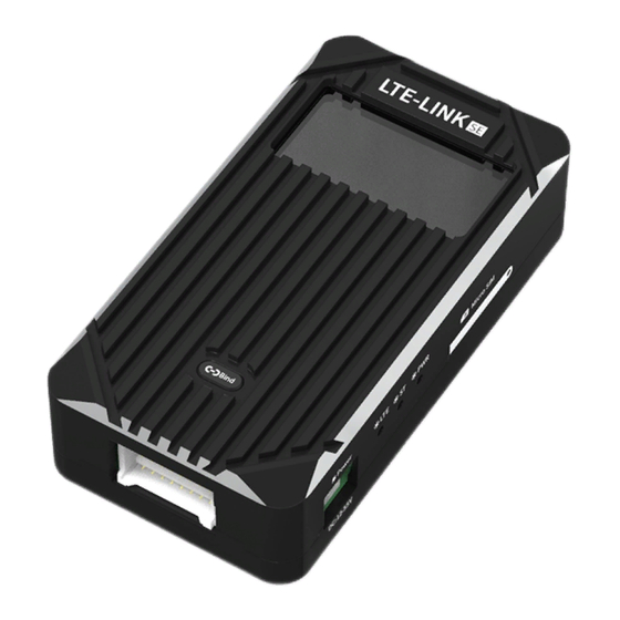
LTE-LINK SE user's Guide 3 Product appearance and interface description 3.1 Product appearance LTE-LINK SE product appearance shown as Figure 3-1. Figure 3- 1 LTE-LINK SE product appearance 3.2 Product hardware and interface description 3.2.1 Hardware interface diagram The product hardware interface is shown in Figure 3-2, Figure 3-3. -
Page 10: Hardware And Interface Description
Figure 3- 3 3.2.2 Hardware and interface description OLED display screen:Display LTE-LINK SE system status information. SIM card slot:Used to access the SIM card. Power status light:Indicates the current power supply situation of the device. If the indicator is found to be off after power-on, it indicates that the power supply of the device is abnormal. -
Page 11: Wiring Instructions
LTE-LINK SE user's Guide Data transmission:Connect to external flight control equipment. HDMI video input:Camera HDMI interface. Fan machine:External fan power supply interface, which can supply power for external cooling fan. Antenna ANT1: The main interface of the network card network signal antenna, which must be connected to the antenna when used. -
Page 12: Hardware Installation And Debugging
OLED screen is not displaying, then check the power indicator status on the LTE-LINK SE. If the power indicator is on but the screen does not display, it is scheduled to be an OLED screen problem. On the contrary, it is the power supply problem of the equipment power supply. -
Page 13: Data Transmission Interface Debugging
Figure 4- 2 Main menu interface 4.2.2 Data transmission interface debugging When the data transmission interface of the LTE-LINK SE device is not connected to the flight control device, it will be indicated by the icon marked as Figure 4-3. When the data... -
Page 14: Hdmi Interface Debugging
Note:The line sequence of the data transmission interface cable connected to the LTE-LINK SE device is fixed and cannot be changed. When connecting the flight control data transmission device, you need to modify it according to the interface line sequence of the connected device. - Page 15 LTE-LINK SE user's Guide Figure 4- 6 HDMI connected to the device status For the HDMI input part, the status information prompt area of the LTE-LINK SE device screen has corresponding status information display. When the screen icon does not change to the HDMI connection status after the HDMI camera device is connected, the user needs to troubleshoot the problem according to the screen status information prompt area displays content.
-
Page 16: Tf Memory Card Interface Debugging
There is a TF memory card access status indicator icon on the main interface of the LTE-LINK SE device screen,shown as Figure 4-9 means the device does not detect the TF memory card access,When it is detected that a TF memory card is connected, the indicator icon will be shown as Figure 4-10. -
Page 17: Sim Card Access And Network Service Connection Debugging
4.2.5 SIM card access and network service connection debugging The LTE-LINK SE device does not support hot swapping of the SIM card, so please insert the SIM card into the SIM card slot and connect two antennas at the same time before powering on the device. -
Page 18: Use And Operation
5.2 Boot interface and system version information When the LTE-LINK SE device is powered on and the screen is normal, it will first display the screen detection interface as shown in Figure 4-1. After the detection interface finish displayed, the product company logo will be displayed shown as Figure 5-1.After the Logo is... -
Page 19: Cuav Cloud Server Connection
LTE-LINK SE user's Guide 5.3 CUAV cloud server connection After the LTE-LINK SE device starts to the main interface, the device will automatically try to connect to the CUAV cloud server. Generally speaking, according to the description in section 4.2.5, after the user inserts the SIM card for debugging, the device can be connected to the CUAV cloud server normally. -
Page 20: Connect To The Public Network
LTE-LINK SE user's Guide 5.3.3 Connect to the public network After the SIM card network registration is successful, the LTE-LINK SE network card device starts to request to connect to the public network, and the status message on the screen interface changes from "sim net register"... -
Page 21: Request To Connect To Cuav Cloud Server
After the device is successfully connected to the CUAV Cloud server, the user can use CUAV cloud's related ground terminal APP to connect to the link device to view the video or control the flight controller.After successfully connecting to the server, the link device screen interface status message information is displayed as "connection eatablish",At the same time, the... -
Page 22: Device Binding And Unbinding
5.4 Device binding and unbinding 5.4.1 Device binding After the LTE-LINK SE device is connected to the CUAV cloud server, the user can bind or unbind the device through the APP software on the CUAV cloud ground terminal. The device... - Page 23 2) The ground terminal APP requests to bind the link device according to the CID code The user enters the corresponding CID code on the binding interface of the CUAV cloud ground terminal APP, and then clicks the "Binding" button to start requesting to bind the terminal link device.
-
Page 24: Device Unbinding
Figure 5- 13 Binding successful 5.4.2 Device unbinding The unbinding of the terminal link LTE-LINK SE device is more simple compared to the binding action. Regardless of whether the link device is online (connected to the CUAV cloud server), the user can complete the device unbinding on the CUAV cloud ground terminal APP Action, please read the relevant APP instructions for details. - Page 25 The LTE-LINK SE terminal link device can transmit the video data on the terminal link device in real time. When the device is connected to the CUAV cloud server and is bound, the user can view video from the terminal link according to the related ground terminal APP of CUAV Cloud.
-
Page 26: Video
LTE-LINK SE user's Guide severely blurred, or it is confirmed that the link device has started to transmit video data, but the ground-side APP has no video images,the fundamental reason is that the current network uplink transmission bandwidth of the SIM cannot reach the bandwidth requirement of the video transmission resolution. -
Page 27: Video Mode
, to start or stop of the recording can be controlled through the on/off button of the CUAV cloud ground terminal APP;Automatic recording is the automatic recording mode set by the user. After the device is powered on next time, it will automatically start recording according to the automatic recording mode set by the user last time. -
Page 28: Several Restrictions On Recording
LTE-LINK SE user's Guide Figure 5- 16 Video record success It should be noted that there is an operational conflict between the active recording mode and the automatic recording mode. For example, the automatic recording mode has allowed the device to start recording, but the user sets the device to start recording on the APP side, and there will be a conflict at this time. -
Page 29: Tf Memory Card Overflow Handling
100MB. 5.8 Taking photos Before using the camera function of the LTE-LINK SE link device, the user needs to debug the HDMI interface and TF memory card of the terminal link device according to chapter 4.2.3 and 4.2.4. -
Page 30: System Version Upgrade
5.9 System version upgrade 5.9.1 Online upgrade After the LTE-LINK SE device is connected to the public network (refer to section 5.3), the device will check the latest version of the current system,when a new version of the system is detected, the device will update the current system to the latest version in the background. -
Page 31: Offline Upgrade
LTE-LINK SE user's Guide kernel upgrade, upgrading device kernel system version. rootfs upgrade, upgrading device root file system version. update fail, this upgrade failed. reboot to update, reset the device to complete this upgrade. When the screen interface status message displays "reboot to update", shown as Figure 5-21, it means that the user can restart the link device to complete the version upgrade. -
Page 32: System Version Configuration Restore
If it is necessary to perform waypoint tasks through link equipment, users should confirm the 4G network coverage on the route before installing LTE-LINK SE equipment; When conditions permit, choose to install the LTE-LINK SE equipment in a location with better heat dissipation;... -
Page 33: Failure Analysis And Troubleshooting
LTE-LINK SE user's Guide 6 Failure analysis and troubleshooting This chapter will list the frequently occurring situations when users use the device and the corresponding solutions. If there are situations not those listed below, please consult relevant technical personnel to solve the problem. Similarly, in the subsequent revision of the document, we will also Supplementary solutions to related problems. - Page 34 LTE-LINK SE user's Guide 4G network signal is poor; Figure 6- 2 Screen interface status message display“lte net disconnect” The LTE network card of the current device is disconnected and the external network service cannot be used. The troubleshooting method is as follows:...
-
Page 35: Status Message Indication Information List
LTE-LINK SE user's Guide Figure 6- 4 6.2 Status message indication information list 6.2.1 Upgrade function message prompt list Form 6- 1 Upgrade function message prompt list Status message on device Introduction uboot upgrade Upgrading device uboot firmware kernel upgrade... -
Page 36: External Device Function Message Prompt List
Status message on device Introduction time sync timeout Network time synchronization timeout/synchronization failure connect to server Request to connect to CUAV cloud server connection eatablish CUAV cloud server successfully connected Network disconnect CUAV cloud server connection is disconnected 6.2.3 External device function message prompt list... -
Page 37: Device Management Control Message Prompt List
LTE-LINK SE user's Guide video record start Video recording starts video record success Video recording success/finish SD error The TF card is not inserted or the inserted TF card is invalid HDMI input error Video input error less 30s failed... -
Page 38: Other Abnormalities
LTE-LINK SE user's Guide 6.3 Other abnormalities When the temperature of the LTE-LINK SE device reaches above 80°C, the performance of the CPU will be greatly reduced, which will cause the entire link system to enter the "overload" state. The user can judge whether the link system has been "overloaded" according to the state of the system status light.
Need help?
Do you have a question about the LTE-LINK SE and is the answer not in the manual?
Questions and answers