Table of Contents

Summary of Contents for Revo C 2PH Series
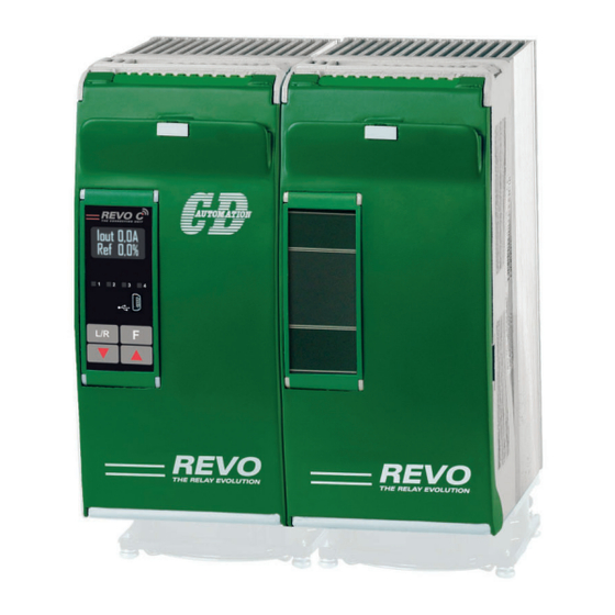
- Page 1 USER’S MANUAL Rev. 02/2022 from 60A to 210A M-RC2-60-210 CD Automation S.r.l. Via Picasso, 34/36 - 20025 Legnano (MI)- Italy Tel. +39 0331 577479 - Fax +39 0331 579479 E-mail: info@cdautomation.com - Web: www.cdautomation.com...
-
Page 3: Declaration Of Conformity
P.I. 08925720156 -Tel. +39 0331 577479 - Fax +39 0331 579479 E-mail: info@cdautomation.com - Web: www.cdautomation.com Declare that the product / Dichiara che il prodotto: Revo C 2Ph 60-210A PRODUCT DESCRIPTION: Electric power control SCOPE OF APPLICATION: Thermal control process DESCRIZIONE DEL PRODOTTO: Unità... -
Page 4: Important Warnings For Safety
User’s manual REVO C 2PH from 60A to 210A Important warnings for safety This chapter contains important information for the safety. The not observance of these instructions may result in serious personal injury or death and can cause serious damages to the Thyristor unit and to the components system included. - Page 5 User’s manual REVO C 2PH from 60A to 210A WARNING! All service including inspection, installation, wiring, maintenance, troubleshooting, fuse or other user serviceable component replacement must be performed only by properly qualified personnel. Service personnel must read this manual before proceeding with work. While service is being performed unqualified personnel should not work on the unit or be allowed in the immediate vicinity.
- Page 6 User’s manual REVO C 2PH from 60A to 210A AVERTISSEMENT! Au moment de relever des mesures de tension ou de courant en direct, utiliser un équipement de protection individuelle approprié pour les tensions et les potentiels d’arc électrique concernés. WARNING! Verify the voltage and current ratings of the power controller are correct for the application.
-
Page 7: Maintenance
User’s manual REVO C 2PH from 60A to 210A Maintenance In order to have a corrected cooling, the user must clean the heat-sink and the protective grill of the fans. The frequency of this servicing depends on environmental pollution. Also check periodically if the screw for the power cables and safety earth are tightened correctly (See Connection Diagram). -
Page 8: Table Of Contents
User’s manual REVO C 2PH from 60A to 210A Summary Declaration of conformity......3 Important warnings for safety . - Page 9 User’s manual REVO C 2PH from 60A to 210A Using the Configurator ......46 10.1 Typical Uses .
-
Page 10: Introduction
User’s manual REVO C 2PH from 60A to 210A Introduction A thyristor unit is semiconductor device which acts as a switch formed by two thyristors in antiparallel. To switch on the alternating current the input signal will be on and the thyristor will switch off at first Zero Crossing voltage with no input signal. -
Page 11: Advantages Compared With Analog Thyristor Unit
Advantages compared with analog thyristor unit Communication RS485 is a standard feature of REVO C this allows the use of many information like: current, power, load state and all the parameters for diagnostic and configuration. Ulterior advantages of the digital system vs the analogical is the flexibility and the possibility of implement special characteristics without change the hardware. -
Page 12: Software Configurator
User’s manual REVO C 2PH from 60A to 210A Software Configurator Thyristor configurator software is free and is possible download it from our site. If the Order Code is in line with requirement, then unit has been already configured in Factory and it’s ready to use. -
Page 13: Quick Start
Attention: this procedure must be carried out by skilled people only. If your REVO C code is in line with what you really need, then the main configuration is already done by Producer and you just need to do the following steps: Verify REVO C current sizing. -
Page 14: Basic Connections And Sizing
User’s manual REVO C 2PH from 60A to 210A Basic Connections and sizing Star wiring with resistive load (control on two phases with REVO C-2PH) 1,73V V = Nominal voltage of the load I = Nominal current of the load... -
Page 15: Identification And Order Code
User’s manual REVO C 2PH from 60A to 210A Identification and Order Code 5.1 Identification of the unit Caution: Before to install, make sure that the Thyristor unit have not damages. If the product has a fault, please contact the dealer from which you purchased the product. -
Page 16: Order Code
User’s manual REVO C 2PH from 60A to 210A 5.2 Order Code REVO C 2PH CURRENT FUSES OPTION description description code description code Fixed Fuses Included No Option Fixed Fuses Included Option code, see code page table 120A Fixed Fuses Included... -
Page 17: Technical Specifications
User’s manual REVO C 2PH from 60A to 210A Technical Specifications 6.1 General features Cover and Socket material: PolymericV2 Utilization Category: AC-51 AC-55b IP Code: Method of Connecting: Load in Delta, Load in Star Auxiliary voltage: Order Code RC2_ _ _-_1 = line voltage 100/120V transformer range 90:135V (8 VA Max) -
Page 18: Environmental Installation Conditions
User’s manual REVO C 2PH from 60A to 210A 6.5 Environmental installation conditions Ambient temperature 0-40°C (32-104°F) at nominal current. Over 40°C-104°F use the derating curve (max 50°C). Storage temperature -25°C to 70°C -13°F to 158°F Installation place Don’t install at direct sun light, where there are conductive dust, corrosive gas, vibration or water and also in salty environmental. -
Page 19: Wi-Fi Transmitter Module
User’s manual REVO C 2PH from 60A to 210A 6.8 Wi-Fi Transmitter Module Models RC_ _ _-_ _ _ _ _-_ _ _ with WiFi option contains a Wi-Fi transmitter module, see model label plate for details on which module is installed. -
Page 20: Installation
User’s manual REVO C 2PH from 60A to 210A Installation Before to install, make sure that the Thyristor unit have not AIR FLOW OUT (V) damages. If the product has a fault, please contact the dealer from which you purchased the product. Verify that the product is the same thing as ordered. -
Page 21: Dimensions And Weight
User’s manual REVO C 2PH from 60A to 210A 7.1 Dimensions and weight REVO C 2PH Size: SR13 SR16 (60A no Fan) (90-210A with Fan) W (mm): D (mm): H (mm): Weight (Kg): 7.2 Fixing holes SR13 (60A no Fan):... -
Page 22: Wiring Instructions
User’s manual REVO C 2PH from 60A to 210A Wiring instructions The Thyristor unit could be susceptible to interferences lost by near equipments or by the power supply, for this reason in accord to the fundamental practices rules is opportune take some precautions: •... - Page 23 User’s manual REVO C 2PH from 60A to 210A Locations of the line power, load, earth ground and control signal connections Cover closed Iout 0.0A Ref. 0.0% 5 4 3 2 1 Ethernet or Profibus port Cover tipped forward...
- Page 24 User’s manual REVO C 2PH from 60A to 210A Suggested wiring mode: connect the cables below, not above. Correct: Maintain adequate distance to avoid obstructing the air flow. See the figure on page 20 Not correct:...
-
Page 25: Control Terminals
User’s manual REVO C 2PH from 60A to 210A 8.3 Control Terminals Warning: Before connecting or disconnecting the unit check that power and control cables are isolated from voltage sources. 8.3.1 Terminal block M1 Terminal Description 0V GND COM I - Common Digital Input DI 2 –... -
Page 26: Schematic
User’s manual REVO C 2PH from 60A to 210A 8.3.4 Terminal block M4 (optional) Terminal connections for Modbus RTU secondary communication option Terminal Description + 24Vdc input. Supplemental power for applications that use communication port (other than Modbus RTU) or FieldBus... - Page 27 2 The auxiliary voltage supply of the REVO C unit must be synchronized with load voltage power supply. If the Auxiliary Voltage (written on the identification label) is different from Supply Voltage (to the load), use an external transformer as designated.
- Page 28 User’s manual REVO C 2PH from 60A to 210A 8.4.1 SSR Control Input schematic For SSR input use follow the schematic below and configure Digital Input 1 as Fast Enable. Analog Input 1 INPUT * SSR Input: 4÷30Vdc 5mA Max (ON >4Vdc / OFF <1Vdc)
-
Page 29: Connection Diagram For 3 Phases (Control On 2 Phases)
User’s manual REVO C 2PH from 60A to 210A 8.5 Connection Diagram for 3 phases (control on 2 phases) Caution: this procedure must be performed only by qualified persons. 131415 16 Analog Inp.1 0-10VDC /4-20mA ANALOG SET POINT Analog Inp.2... -
Page 30: Control Panel
User’s manual REVO C 2PH from 60A to 210A Control Panel The Control Panel is placed on the front of the thyristor unit, on his display you can visualize the alarms, the input and output signals and all the configuration parameters. -
Page 31: Menu Navigation
User’s manual REVO C 2PH from 60A to 210A 9.1 Menu navigation The menus are accessible using the control panel keypad and display. Choose Enter Choose Edit HOME PAGE Menu Password Parameter Parameter Iout0.0A Password Set Point Iout0.0A 100% SP 100% Iout0.0A... -
Page 32: Control Panel Led
User’s manual REVO C 2PH from 60A to 210A 9.2 Control Panel Led The four indicators on the control panel show the general state of the power controller. Flashing Power output set locally or via communications Local/Remote Power output set remotely (via analog input) -
Page 33: Parameter List
User’s manual REVO C 2PH from 60A to 210A 9.4 Parameter list This chapter describes the parameter on the menus accessed via the control panel and Configurator software. To learn how to access the menus described below see “Menu navigation” chapter. - Page 34 User’s manual REVO C 2PH from 60A to 210A 9.4.1 Operator Menu This section describes each item on the operator menu. Use this menu to view the measured values and basic settings of the power controller. The password to access this menu is 0.
- Page 35 User’s manual REVO C 2PH from 60A to 210A 9.4.2 Setup Menu This section describes each item on the setup menu. Use this menu to configure the power controller for the load. The password to access this menu is 2.
- Page 36 User’s manual REVO C 2PH from 60A to 210A 9.4.3 Advanced Setup Menu This section describes each item on the advanced setup menu. Use this menu to configure the power switching, closed loop control of power and adjustable settings for data logging and heater bakeout. The password to access this menu is 10.
- Page 37 User’s manual REVO C 2PH from 60A to 210A Modbus Par. Parameter Name Description Default Range Unit Address Type Set the gain for the main loop. A larger Pb Power Read value yields a larger adjustment for a 0 to 255...
- Page 38 User’s manual REVO C 2PH from 60A to 210A 9.4.4 Hardware Menu This section describes each item on the hardware menu. Use this menu to configure how the inputs and outputs are used in the application. The password to access this menu is 5.
- Page 39 User’s manual REVO C 2PH from 60A to 210A Modbus Par. Parameter Name Description Default Address Type DI1 Functn Choose how the signal detected by digital input 1 Read is used Write Option Description Value Enable Enable power output V Feedback...
- Page 40 User’s manual REVO C 2PH from 60A to 210A Modbus Par. Parameter Name Description Default Address Type Alm Out Fn Choose for which conditions the digital output indicates alarm. The output always indicate an alarm when the heat sink is over temperature. The...
- Page 41 User’s manual REVO C 2PH from 60A to 210A Modbus Par. Parameter Name Description Default Range Address Type Set the value of retransmitted parameter Rtx Scale to be represented by the full scale of the Read 0 to 9999 analog output.
- Page 42 User’s manual REVO C 2PH from 60A to 210A 9.4.5 Communication Menu This section describes each item on the communication menu. Use this menu to configure the communication options. The password to access this menu is 3. Modbus Par. Parameter Name...
- Page 43 User’s manual REVO C 2PH from 60A to 210A Modbus Par. Parameter Name Description Default Range Unit Address Type Set the amount of time to wait for WD Reset Read communication message before 0 to 255 Write triggering the watchdog error...
- Page 44 User’s manual REVO C 2PH from 60A to 210A 9.4.6 Monitoring Menu This section describes each item on the monitoring menu. Use this menu to view the states of digital input, values of analog input and information about the power controller such as serial number and software version.
- Page 45 User’s manual REVO C 2PH from 60A to 210A Modbus Par. Parameter Name Description Range Unit Address Type Analog In1 Indicates the percent of full scale measured Read 0 to 100.0 by analog input 1 Only Analog In2 Indicates the percent of full scale measured Read 0 to 100.0...
-
Page 46: Using The Configurator
User’s manual REVO C 2PH from 60A to 210A Using the Configurator Confi gurator software can be used like an alternative of the power controller’s keypad and set the advanced features not available via the power controller’s onboard user interface. - Page 47 RS485 port so a USB-to-485 converter is required. 3) Launch the Confi gurator software an select REVO C: for single phase REVO C 2PH: for 2 phase power controller REVO C 3PH: for 3 phase power controller...
-
Page 48: Using The Configurator
User’s manual REVO C 2PH from 60A to 210A 10.5 Using the Confi gurator After software has been installed, communication has been set up and model type selected, is possible operate with power controller. 10.5.1 To view or save a power controller’s settings using “Simple”... - Page 49 User’s manual REVO C 2PH from 60A to 210A 10.5.3 To download a recipe fi le into a power controller: 1) Click Simple, if not already on the Simple view 2) Click existing recipe Open 3) Locate and select the recipe fi le and click...
- Page 50 User’s manual REVO C 2PH from 60A to 210A 10.5.8 To reset the power totals: 1) Click Test, if not already on the test view 2) Click Online 3) Click Reset Totals 4) Click 10.5.9 Setting Up and Using Data Logging...
-
Page 51: Software General Information
Instruments selector Select the right instrument to use: HOME: the default view REVO-C: open the Simple and Test views for a single-phase power controller 3PH: access the Simple and Test views for a three-phase power controller REVO-C MSG: opens a serial communication message view Status Bar Indicates information such as time and date, communications port and baud rate. - Page 52 User’s manual REVO C 2PH from 60A to 210A 10.6.2 Simple Section This section is used to create, save, upload and download recipes of parameters settings. Can be used also to see the settings in a controller. Simple page is the default page when select the model using the Model Button, but If not selected is possible access it clicking the Simple tab below the main menu.
- Page 53 User’s manual REVO C 2PH from 60A to 210A 10.6.3 Test Section This section is used to monitor and adjust the operation of the power controller in real time using RS485 or USB communication port. After select the model, is possible access to this section clicking the “TEST”...
- Page 54 User’s manual REVO C 2PH from 60A to 210A Buttons setup options: Firing: view and set the fi ring type and the associated parameters Feedback: view and set feedback type Communication: view and set communication options for ports, protocols and fi eldbus...
- Page 55 User’s manual REVO C 2PH from 60A to 210A 10.6.4. Load Analyzer Load Analyzer is used for monitoring values graphically represent Click on Load Analyzer button on the test page will open Load Analyzer window. Is possible see 3 channels (Ch 1, Ch 2 and Ch 3).
- Page 56 User’s manual REVO C 2PH from 60A to 210A 10.6.5 Data Log Window In the power controller the data log window is used to manage fi les and set up logging parameter like log interval time and date/time in rtc slider: Enable and disable data logging function.
- Page 57 User’s manual REVO C 2PH from 60A to 210A 10.6.7 MSG view Message view display the communication activity between the computer and the power controller. PORT COM: use this view to see when the COM port is accessed and its settings...
-
Page 58: Configurable Inputs And Outputs
2PH from 60A to 210A Configurable Inputs and Outputs The REVO C power controller features two digital inputs, up to two analog inputs and a relay output. Some models also include an analog output for retransmitting a measured value to other automation equipment. -
Page 59: Analog Input 2: Set Point Or Feedback
User’s manual REVO C 2PH from 60A to 210A 11.3 Analog Input 2: Set Point or Feedback What this input does is user-configurable. Connect an analog signal that indicates: • An alternate set point signal • Measured power, voltage or current from an external device used as feedback. -
Page 60: Alarm Description
User’s manual REVO C 2PH from 60A to 210A Alarm description 12.1 Heater Break Alarm This option allows you to diagnose any load breakage. The diagnostics is based on the comparison of the value of the nominal resistance of the load with respect to the resistance measured in real time. The nominal resistance is calculated using the Operative Load Voltage (Nom Line V) and Nominal Current of the load (Nominal I) parameters. -
Page 61: Aux High
User’s manual REVO C 2PH from 60A to 210A 12.2. AUX High This alarm is displayed when the auxiliary supply voltage exceeds the established ranges. If the alarm situation persists for more than 5 seconds, the unit will go into protection. -
Page 62: 13 "Enable" Function In Static Unit
User’s manual REVO C 2PH from 60A to 210A “Enable” Function in static Unit The “Enable” function can work in several ways • from Digital input • from Serial Port • from Digital Input + Serial Port • from FieldBus •... -
Page 63: Using Serial Port Rs485 Only
User’s manual REVO C 2PH from 60A to 210A 13.2 Using Serial Port RS485 only The static unit has an RS485 Modbus RTU serial port always present. By setting the Digital Input as “Not Used” or different from “Enable” it is possible to control the enable from... -
Page 64: Using Fieldbus Only
User’s manual REVO C 2PH from 60A to 210A 13.4 Using FieldBus only The static unit as an option can be ordered with a FieldBus (Ex: profinet). This option continuously writes the values on the unit keeping them up to date. -
Page 65: Using Digital Input + Fieldbus
User’s manual REVO C 2PH from 60A to 210A 13.5 Using Digital Input + FieldBus The static unit as an option can be ordered with a FieldBus (Ex: profinet). This option continuously writes the values on the unit keeping them up to date. -
Page 66: Firing Type
User’s manual REVO C 2PH from 60A to 210A Firing type Choose a correct firing type allows to optimize the thyristor unit for the installed load. The firing type has already configured in line with customer requirements that are defined in the Order Code. -
Page 67: Control Mode (Feed-Back)
User’s manual REVO C 2PH from 60A to 210A Control Mode (feed-back) The Control Mode (feed-back) type has already configured in line with customer requirements that are defined in the Order Code. The Order Code is written on the identification label. -
Page 68: Supply The Electronic Board
2PH from 60A to 210A Supply the electronic board The REVO C thyristor unit, to work, requires a voltage supply for the electronic boards. The Max consumption is 10VA.The voltage supply for the electronic boards is configured in line with customer requirements that are defined in the Order Code. -
Page 69: 24Vdc Input Auxiliary Supplemental Power
User’s manual REVO C 2PH from 60A to 210A 24Vdc input Auxiliary supplemental power (option) The 24Vdc Auxiliary Supply input in Terminal Block M4 (optional), terminals 1 and 2, can be used as an auxiliary power supply when the main network fails. This auxiliary power supply keeps the communication circuits powered allowing data to be transferred to the supervision system –... -
Page 70: Rs485 Serial Port
Terminal M1 Description Command Terminals.. RS485 A+ On this port may be done a network up to 127 REVO C. RS485 B- Fieldbus communication option Other serial communication port are available as option, see Communication Manual for details. Ethernet Configuration... -
Page 71: Internal Fuse
User’s manual REVO C 2PH from 60A to 210A Internal Fuse The thyristor unit have internal fuse extrarapid at low I T for the thyristor protection of against the short-circuits. The Fuses must have I T 20% less than thyristor’s I T. -
Page 72: Fuses Replacement
User’s manual REVO C 2PH from 60A to 210A 20.1 Fuses Replacement Open the cover and remove the screws, then replace it with the correct fuse, use the screws with a proper suggested torque indicated below: Torque Torque Type Screw... - Page 73 CD Automation S.r.l. Via Picasso, 34/36 - 20025 Legnano (MI)- Italy Tel. +39 0331 577479 - Fax +39 0331 579479 E-mail: info@cdautomation.com - Web: www.cdautomation.com...
Need help?
Do you have a question about the C 2PH Series and is the answer not in the manual?
Questions and answers