Table of Contents
Advertisement
Quick Links
INSTALLATION, OPERATION, AND MAINTENANCE MANUAL
Table of Contents
1
INTRODUCTION ....................................................................................................................................................................................................... 3
1.1
................................................................................................................................................................................................................... 3
1.2
......................................................................................................................................................................................................... 3
2
ENVIRONMENTAL, HEALTH, AND SAFETY ........................................................................................................................................................... 3
2.1
2.2
.................................................................................................................................................................................................................... 3
3
PRODUCT DESCRIPTION AND FEATURES ............................................................................................................................................................ 3
4
IDENTIFICATION AND MARKINGS .......................................................................................................................................................................... 4
4.1
......................................................................................................................................................................................................... 4
4.2
V
5
FACTORY AND FIELD APPLIED COATINGS .......................................................................................................................................................... 5
6
UNLOADING AND STORAGE .................................................................................................................................................................................. 5
7
VALVE INSTALLATION ............................................................................................................................................................................................ 6
7.1
7.2
V
7.3
V
7.4
V
7.5
7.6
............................................................................................................................................................................................... 9
8
OPERATION.............................................................................................................................................................................................................. 9
8.1
V
8.2
9
TROUBLESHOOTING ............................................................................................................................................................................................. 10
9.1
V
................................................................................................................................................................................................. 10
9.2
V
10
MAINTENANCE ...................................................................................................................................................................................................... 10
KEROTEST WELDBALL BALL VALVE
INSTALLATION, OPERATION, AND
MAINTENANCE MANUAL
KEROTEST WELDBALL
....................................................................................................................................................................................... 3
) ....................................................................................................................................................................................... 4
V
.............................................................................................................................................. 6
................................................................................................................................................................... 7
........................................................................................................................................................ 8
.................................................................................................................................................................... 8
.................................................................................................................................................................................. 9
............................................................................................................................................................ 9
..................................................................................................................................................................................... 10
.................................................................................................................................................................................. 10
........................................................................................................................................................................ 11
............................................................................................................................................................................. 11
®
BALL VALVE
............................................................................................................................................. 6
........................................................................................................................................ 10
NO.: K-1484
REV.: A
DATE: 03MAR2022
PAGE: 1 OF 17
Advertisement
Table of Contents

Subscribe to Our Youtube Channel
Related Manuals for Kerotest WELDBALL


Summary of Contents for Kerotest WELDBALL
-
Page 1: Table Of Contents
NO.: K-1484 KEROTEST WELDBALL BALL VALVE REV.: A INSTALLATION, OPERATION, AND DATE: 03MAR2022 MAINTENANCE MANUAL PAGE: 1 OF 17 ® KEROTEST WELDBALL BALL VALVE INSTALLATION, OPERATION, AND MAINTENANCE MANUAL Table of Contents INTRODUCTION ........................................3 ........................................... 3 COPE ......................................... 3 EFERENCES ENVIRONMENTAL, HEALTH, AND SAFETY ................................ - Page 2 Figure 11 Do Not Use at the End of a Pipeline .................................. 8 Figure 12 End of Pipeline Pup and Cap..................................... 8 Figure 13 Manual Gear Adjustment ....................................11 Figure 14 Stem Seal.......................................... 12 Figure 15 Operating Square Components ..................................13 Figure 16 Weldball Components ..................................... 14...
-
Page 3: Introduction
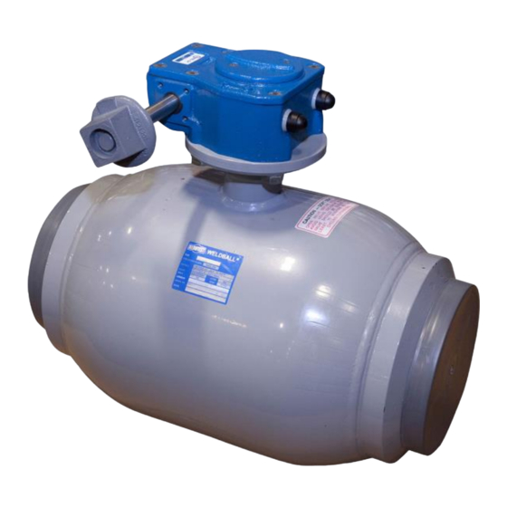
3 PRODUCT DESCRIPTION AND FEATURES Weldball ball valves are welded steel valves used in natural/fuel gas distribution pipelines and are available in NPS 3/4 through NPS 12, Full Port (FP) / Reduced Port (RP), and in ASME/ANSI Pressure Classes 150 and 300, and 500 CWP. -
Page 4: Identification And Markings
Gear Operator option for NPS 6 FP and larger *The Kerotest Ultra-Stop feature is a heavy duty operating square limit stop designed to accommodate applied excessive torque during field operation. It can be identified by a notched plate welded to the valve neck and a pin on the operating square within the notch or as an integral collar and pin. -
Page 5: Factory And Field Applied Coatings
5 FACTORY AND FIELD APPLIED COATINGS The standard factory coating supplied on Weldball is a gray epoxy powder coat not suitable for outdoor or buried service. It is recommended the customer apply an appropriate coating to the entire valve exterior. -
Page 6: Valve Installation
These instructions must be followed carefully when installing the valve. These general instructions do not cover all possible operating scenarios. For more specific guidance on the use of the valve or its suitability for an intended use, please contact Kerotest. •... -
Page 7: Installation Of Valve With Flanges
NO.: K-1484 KEROTEST WELDBALL BALL VALVE REV.: A INSTALLATION, OPERATION, AND DATE: 03MAR2022 MAINTENANCE MANUAL PAGE: 7 OF 17 • The welder must be qualified in accordance with relevant sections of API 1104, section IX of the ASME Boiler and Pressure Vessel Code (ASME BPVC), or company approved and qualified welding standard. -
Page 8: Installation Of Valve With Screwed Ends
Standard end flange facing is 1/16" raised face with phonographic finish. Some valves may be ordered with a flat face finish. Contact Kerotest or your distributor for further information and availability of flat face finished valves. Flat face finished valves are slightly shorter than standard faced valves, as allowed per ASME B16.10. -
Page 9: Pressure Testing
NO.: K-1484 KEROTEST WELDBALL BALL VALVE REV.: A INSTALLATION, OPERATION, AND DATE: 03MAR2022 MAINTENANCE MANUAL PAGE: 9 OF 17 Pressure Testing During installed valve testing, maximum allowable test pressure is 1.1x the marked rating when the valve is closed and 1.5x the marked rating when the valve is open. -
Page 10: Troubleshooting
NOTE: Avoid removing the gear operator from the valve. The gear operator has been adjusted at the factory to ensure that the valve is leak-free. If the gear operator is removed, it may have to be re-adjusted. Kerotest does not accept responsibility for adjustments of customer installed gear operators. Refer to section 10.4 for adjustment instructions. -
Page 11: Gear Operator Reinstallation
NO.: K-1484 KEROTEST WELDBALL BALL VALVE REV.: A INSTALLATION, OPERATION, AND DATE: 03MAR2022 MAINTENANCE MANUAL PAGE: 11 OF 17 10.3 Gear Operator Reinstallation Part numbers mentioned in this section refer to Figure 13. 1. When reinstalling the gear operator onto the valve, check that the gear is in the correct position using the marks made in during removing in section 10.2. -
Page 12: Stem Seal O-Ring Replacement
NO.: K-1484 KEROTEST WELDBALL BALL VALVE REV.: A INSTALLATION, OPERATION, AND DATE: 03MAR2022 MAINTENANCE MANUAL PAGE: 12 OF 17 10.5 Stem Seal O-Ring Replacement Valve must be in closed position if valve will be under pressure during this procedure. Assembly and components may vary by valve size and date of manufacture. -
Page 13: Replacing Operating Square With Gear Operator On Nps 6 Fp / 8 Rp Valves
NO.: K-1484 KEROTEST WELDBALL BALL VALVE REV.: A INSTALLATION, OPERATION, AND DATE: 03MAR2022 MAINTENANCE MANUAL PAGE: 13 OF 17 10.6 Replacing Operating Square with Gear Operator on NPS 6 FP / 8 RP Valves Removing Operating Square 1. Cycle valve to full open position. -
Page 14: Components
MAINTENANCE MANUAL PAGE: 14 OF 17 11 GENERAL COMPONENTS Figure 16 General Weldball Components 1. Body - Carbon steel, all welded, high strength, lightweight design 2. Stem - Stainless steel, blow-out proof design 3. Stem Seals - Buna-N, 2 O-rings provide an effective seal within a temperature range of -20°F to 200°F 4. -
Page 15: Physical Specifications
NO.: K-1484 KEROTEST WELDBALL BALL VALVE REV.: A INSTALLATION, OPERATION, AND DATE: 03MAR2022 MAINTENANCE MANUAL PAGE: 15 OF 17 12 PHYSICAL SPECIFICATIONS Table 3 Valve Dimensions, Weight, and Cv... -
Page 16: Factory Testing
NO.: K-1484 KEROTEST WELDBALL BALL VALVE REV.: A INSTALLATION, OPERATION, AND DATE: 03MAR2022 MAINTENANCE MANUAL PAGE: 16 OF 17 13 FACTORY TESTING To be certain that all valves shipped from the factory are bubble tight, they are subjected to the following tests in accordance with ASME B16.34... -
Page 17: Document Revision History
5500 Second Avenue Pittsburgh, PA 15207 Telephone: (412) 521-4200 www.kerotest.com sales@kerotest.com Prior Document Releases: This procedure was previously distributed as “Kerotest Weldball Valve Operations Manual WB-001”. Description Written By Approval Approval Date Added 6" and 8" short end to end flange end 09-09-1989 dimensions;...
Need help?
Do you have a question about the WELDBALL and is the answer not in the manual?
Questions and answers