Table of Contents
Advertisement
Quick Links
UM11637
FRDMGD3160DCMHB evaluation board
Rev. 2 — 3 February 2022
Document information
Information
Content
Keywords
GD3160, DCM
Abstract
This document describes the operation of the FRDMGD3160DCMHB
evaluation board, compatible with the DCM
™
1000X SiC, high-voltage gate driver, SiC power module
User guide
™
1000X SiC evaluation kit.
Advertisement
Table of Contents

Subscribe to Our Youtube Channel
Summary of Contents for SAFEASSURE FRDMGD3160DCMHB
- Page 1 Rev. 2 — 3 February 2022 User guide Document information Information Content Keywords GD3160, DCM ™ 1000X SiC, high-voltage gate driver, SiC power module Abstract This document describes the operation of the FRDMGD3160DCMHB evaluation board, compatible with the DCM ™ 1000X SiC evaluation kit.
- Page 2 UM11637 NXP Semiconductors FRDMGD3160DCMHB evaluation board Revision history Date Description 20220203 release version Modifications: • Update with latest board images 20210921 initial version UM11637 All information provided in this document is subject to legal disclaimers. © NXP B.V. 2022. All rights reserved.
-
Page 3: Important Notice
UM11637 NXP Semiconductors FRDMGD3160DCMHB evaluation board Important notice IMPORTANT NOTICE For engineering development or evaluation purposes only NXP provides the product under the following conditions: This evaluation kit is for use of ENGINEERING DEVELOPMENT OR EVALUATION PURPOSES ONLY. It is provided as a sample IC pre- soldered to a printed-circuit board to make it easier to access inputs, outputs and supply terminals. -
Page 4: Getting Started
The tool summary page for FRDMGD3160DCMHB is at http://www.nxp.com/ FRDMGD3160DCMHB. The overview tab provides an overview of the device, product features, a description of the kit contents, a list of (and links to) supported devices, a list of (and links to) any related products, and a Get Started section. -
Page 5: System Requirements
Getting to know the hardware 4.1 Overview The FRDMGD3160DCMHB is a half-bridge evaluation kit populated with two GD3160 single channel gate drive devices. The kit includes the Freedom KL25Z microcontroller hardware for interfacing a PC installed with FlexGUI software for communication to the serial peripheral interface (SPI) registers on the GD3160 gate drive devices in either daisy chain or standalone configuration. -
Page 6: Device Features
> 125 kW 4.4 Board description The FRDMGD3160DCMHB is a half-bridge or three-phase evaluation board populated with two GD3160 single channel IGBT or SiC gate drive devices. The board supports connection to an FRDM-KL25Z microcontroller for SPI communication configuration programming and monitoring. -
Page 7: Low-Voltage Logic And Control Connector
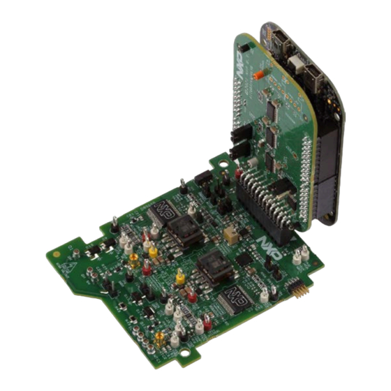
UM11637 NXP Semiconductors FRDMGD3160DCMHB evaluation board Figure 2. Connecting FRDM-KL25Z, GD31xx half-bridge EVB and translator board 4.4.1 Low-voltage logic and control connector Low-voltage domain is 12 V VSUP domain that interfaces with the MCU and GD3160 control registers through the 24-pin connector interface. - Page 8 UM11637 NXP Semiconductors FRDMGD3160DCMHB evaluation board Figure 3. Evaluation board voltage and interface domains Table 2. Low-voltage domain 24-pin connector definitions Name Function AOUTL analog output duty cycle encoded signal (low side) for reading temperature via TSENSEA or DC link voltage via AMUXIN n.c.
-
Page 9: Test Point Definitions
UM11637 NXP Semiconductors FRDMGD3160DCMHB evaluation board Table 2. Low-voltage domain 24-pin connector definitions ...continued Name Function INTAL fault reporting and real time V and VGE monitoring (low side) MOSIH master out slave in (high side) INTAH fault reporting and real time V... - Page 10 UM11637 NXP Semiconductors FRDMGD3160DCMHB evaluation board Table 3. Test point definitions Test point Definition Low-voltage domain VSUP DC voltage source connection point for VSUP power input of GD3160 devices. Supply 12 V DC between this point and GND. grounding points for low-voltage domain...
-
Page 11: Power Supply And Jumper Configuration
UM11637 NXP Semiconductors FRDMGD3160DCMHB evaluation board 4.4.3 Power supply and jumper configuration Figure 5. Power supply and jumper configuration Table 4. Jumper definitions Jumper Position Function PWMHSEL (J11) 1-2 (default) dead time fault protection enabled (high side) dead time fault protection disabled (use for short-circuit testing) -
Page 12: Bottom View
UM11637 NXP Semiconductors FRDMGD3160DCMHB evaluation board Table 4. Jumper definitions ...continued Jumper Position Function PS_EN (J1) MCU control of flyback supply enable 2-3 (default) flyback supply enable tied to VSUP 4.4.4 Bottom view Figure 6. Evaluation board bottom view UM11637 All information provided in this document is subject to legal disclaimers. -
Page 13: Gate Drive Resistors
UM11637 NXP Semiconductors FRDMGD3160DCMHB evaluation board 4.4.5 Gate drive resistors • RGH - gate high resistor in series with the GH pin at the output of the GD3160 gate ™ high driver and DCM 1000X module gate that controls the turn-on current for SiC MOSFET gate. -
Page 14: Kinetis Kl25Z Freedom Board
UM11637 NXP Semiconductors FRDMGD3160DCMHB evaluation board 4.5 Kinetis KL25Z Freedom board The Freedom KL25Z is an ultra low-cost development platform for Kinetis L series MCU built on Arm Cortex-M0+ processor. Figure 8. Freedom development platform UM11637 All information provided in this document is subject to legal disclaimers. -
Page 15: To 5.0 V Translator Board
UM11637 NXP Semiconductors FRDMGD3160DCMHB evaluation board 4.6 3.3 V to 5.0 V translator board KITGD316xTREVB translator enables level shifting of signals from MCU 3.3 V to 5.0 V SPI communication. Figure 9. Translator board Table 5. Translator board jumper definitions Jumper Position... -
Page 16: Configuring The Hardware
NXP Semiconductors FRDMGD3160DCMHB evaluation board Configuring the hardware The FRDMGD3160DCMHB board can be used in half-bridge mode to evaluate a single power module by running double pulse and short-circuit tests. Alternatively, three FRDMGD3160DCMHB boards can be chained together to evaluate ™... -
Page 17: Quick Start
1. Download and install the latest FlexGUI software (see Installing FlexGUI on your computer) 2. Assemble the FRDMGD3160DCMHB with the translator board and KL25Z on the power module as shown in Figure 10 3. Check jumper configuration on the evaluation board before powering up, and ensure that the configuration meets desired use case. -
Page 18: Daisy Chain Spi Configuration
UM11637 NXP Semiconductors FRDMGD3160DCMHB evaluation board Figure 11. Normal mode SPI for half-bridge configuration 5.1.4 Daisy chain SPI configuration To access the GD3160 in daisy chain mode, check the position of the following jumpers: Table 7. Daisy chain SPI jumpers configuration Designator... - Page 19 UM11637 NXP Semiconductors FRDMGD3160DCMHB evaluation board Figure 12. Daisy chain 1 × 2 for half-bridge configuration UM11637 All information provided in this document is subject to legal disclaimers. © NXP B.V. 2022. All rights reserved. User guide Rev. 2 — 3 February 2022...
-
Page 20: Three-Phase Configuration
3 × DCM 1000X SiC power modules, DC link capacitor, cooler plate, and mounting hardware • 3 × FRDMGD3160DCMHB, 1 × KITGD316xTREVB and 1 × FRDM-KL25Z • Rogowski coil high-current probe • High-voltage differential voltage probe • High sample rate digital oscilloscope with probes •... -
Page 21: Quick Start
2. Assemble the DCM 1000X SiC kit: a. Assemble the three FRDMGD3160DCMHB boards together making sure that the board edge connectors J25 and J26 are correctly plugged into each other. The letters U, V, and W identify the boards according to Figure b. - Page 22 UM11637 NXP Semiconductors FRDMGD3160DCMHB evaluation board Figure 14. Daisy chain 1 × 6 for three-phase board configuration UM11637 All information provided in this document is subject to legal disclaimers. © NXP B.V. 2022. All rights reserved. User guide Rev. 2 — 3 February 2022...
-
Page 23: Installation And Use Of Software Tools
FRDMGD3160DCMHB evaluation board Installation and use of software tools Software for FRDMGD3160DCMHB is distributed with the FlexGUI tool (available on NXP.com). Necessary firmware comes pre-installed on the FRDM-KL25Z with the kit. Even if the user intends to test with other software or PWM, it is recommended to install this software as a backup or to help debugging. -
Page 24: Using The Flexgui
The device may not appear as a distinct device to the computer while connected through the KL25Z USB port, this is normal. 8. The FRDM-KL25Z board is now fully set up to work with FRDMGD3160DCMHB and the FlexGUI. a. There is no software stored or present on either the driver or translator boards, only on the FRDM-KL25Z MCU board. - Page 25 UM11637 NXP Semiconductors FRDMGD3160DCMHB evaluation board FlexGUI settings • Access settings by selecting Settings from the File menu Figure 16. GUI settings menu • The Loader and Logs settings are shown below: Figure 17. Loader settings UM11637 All information provided in this document is subject to legal disclaimers.
- Page 26 UM11637 NXP Semiconductors FRDMGD3160DCMHB evaluation board Figure 18. Logs settings • Access settings by selecting Settings from the File menu. • The Register Map and Tabs settings are shown below: Figure 19. Register map settings UM11637 All information provided in this document is subject to legal disclaimers.
- Page 27 UM11637 NXP Semiconductors FRDMGD3160DCMHB evaluation board Figure 20. Tabs settings Command Log window • The Command Log area informs the user about application events. Figure 21. Command Log area UM11637 All information provided in this document is subject to legal disclaimers. © NXP B.V. 2022. All rights reserved.
- Page 28 UM11637 NXP Semiconductors FRDMGD3160DCMHB evaluation board Global workspace controls • Always visible in the lower left corner of the main application window. – GD3160 tab functionality – Switch modes between run and configuration mode – Set SPI frequency Figure 22. Device pins settings and status menus •...
- Page 29 UM11637 NXP Semiconductors FRDMGD3160DCMHB evaluation board • Status tab functionality – Monitors Status 1 and Status 2 fault bits. Bits that are set are shown in red. – Ability to clear all faults and automatically poll status registers. Figure 24. Status tab functionality •...
- Page 30 UM11637 NXP Semiconductors FRDMGD3160DCMHB evaluation board Register map • Registers are grouped according to function; independent lines to read and write the registers • Individual registers can be read by clicking the R button and can be written by using the W button.
- Page 31 UM11637 NXP Semiconductors FRDMGD3160DCMHB evaluation board Gate Drive tab • Allows setting of parameters related to the gate drive; controls are disabled when not in config mode • Provides a more intuitive visual way to set parameters • All settings are automatically synchronized with the register controls.
- Page 32 UM11637 NXP Semiconductors FRDMGD3160DCMHB evaluation board Current Sense tab • Allows setting of parameters related to current sense • Provides a more intuitive visual way to set parameters • All settings are automatically synchronized with the register controls. Figure 28. Current sense tab UM11637 All information provided in this document is subject to legal disclaimers.
- Page 33 UM11637 NXP Semiconductors FRDMGD3160DCMHB evaluation board DESAT & Seg Drive tab • Allows setting of parameters related to desat and segmented drive • Provides a more intuitive visual way to set parameters • All settings are automatically synchronized with the register controls.
- Page 34 UM11637 NXP Semiconductors FRDMGD3160DCMHB evaluation board Overtemperature tab • Allows setting of parameters related to overtemperature and overtemperature warning thresholds • Provides a more intuitive visual way to set parameters • All settings are automatically synchronized with the register controls.
- Page 35 UM11637 NXP Semiconductors FRDMGD3160DCMHB evaluation board Undervoltage and overvoltage threshold tab • Allows setting of parameters related to undervoltage and overvoltage threshold • Provides a more intuitive visual way to set parameters • All settings are automatically synchronized with the register controls.
- Page 36 UM11637 NXP Semiconductors FRDMGD3160DCMHB evaluation board Measurements tab • Allows monitoring and graphing of ADC and temperature values Figure 32. Measurements tab UM11637 All information provided in this document is subject to legal disclaimers. © NXP B.V. 2022. All rights reserved.
- Page 37 UM11637 NXP Semiconductors FRDMGD3160DCMHB evaluation board Status tab • Allows monitoring of Status 1, Status 2, and Status 3 register values • Status 1 and Status 2 faults can be cleared • Status mask registers can be modified when in configuration mode Figure 33. Status tab...
-
Page 38: Troubleshooting
UM11637 NXP Semiconductors FRDMGD3160DCMHB evaluation board 6.4 Troubleshooting Some common issues and troubleshooting procedures are detailed below. This is not an exhaustive list by any means, and additional debug may be needed: Problem Evaluation Explanation Corrective action(s) No PWM output (no fault reported) -
Page 39: Schematics, Board Layout, And Bill Of Materials
The board schematics, board layout, and bill of materials are available at http:// www.nxp.com/FRDMGD3160DCMHB on the Overview tab under Get Started. References Tool summary page for FRDMGD3160DCMHB http://www.nxp.com/FRDMGD3160DCMHB Product summary page for GD3160 device http://www.nxp.com/GD3160 UM11637 All information provided in this document is subject to legal disclaimers. -
Page 40: Legal Information
NXP does not accept any liability in this respect. Danfoss - is a trademark of Danfoss A/S. Kinetis — is a trademark of NXP B.V. SafeAssure — is a trademark of NXP B.V. UM11637 All information provided in this document is subject to legal disclaimers. - Page 41 UM11637 NXP Semiconductors FRDMGD3160DCMHB evaluation board Tables Tab. 1. Device features ..........6 Tab. 5. Translator board jumper definitions ....15 Tab. 2. Low-voltage domain 24-pin connector Tab. 6. Normal mode SPI jumpers configuration ..17 definitions ............8 Tab. 7.
-
Page 42: Table Of Contents
UM11637 NXP Semiconductors FRDMGD3160DCMHB evaluation board Contents Important notice ..........3 FRDMGD3160DCMHB ......... 3 Getting started ............ 4 Kit contents/packing list ........4 Required equipment .......... 4 System requirements .........5 Getting to know the hardware ......5 Overview ............5 Board features ...........
Need help?
Do you have a question about the FRDMGD3160DCMHB and is the answer not in the manual?
Questions and answers