Table of Contents
Advertisement
Quick Links
Advertisement
Table of Contents

Related Manuals for Dwarf Connection DC-LINK ULR1

Summary of Contents for Dwarf Connection DC-LINK ULR1
- Page 1 ULR1 user maNual X.LiNK-L1...
-
Page 2: Table Of Contents
Contents • Introduction • Safety Precautions • Overview • Characteristics • Description Transmitter • Description Receiver • Operation • Antenna Positioning • Features • Maintenance • Troubleshooting • Technical Specifications • Regulatory Information • Notes In all EU member states, operation of 5150-5250MHz is restricted to indoor use only. -
Page 3: Introduction
Congratulations on purchasing the DC-LINK video transmission system! Please read this manual carefully before operating your product. You can also access this through our website: www.dwarfconnection.com Also read the safety information enclosed with your DwarfConnection product, as it contains more detailed information on product and health safety! The technology contained in this product, including the device itself as well as related software and trademarks, is protected by law. -
Page 4: Safety Precautions
Safety Precautions WARNING: READ BEFORE USE TO REDUCE THE RISK OF PERSONAL INJURY OR PROPERTY DAMAGE, INCLUDING DAMAGE TO YOUR TRANSMITTER/RECEIVER AND OTHER POTENTIAL HAZARDS. HANDLING Handle your DC-LINK system with care. You may damage the devices if you disassemble, drop, bend, burn, crush or otherwise subject them to un necessary force. -
Page 5: Overview
PROLONGED HEAT EXPOSURE Your DC-LINK system generates heat during normal operation and complies with applicable surface temperature standards and limits. Avoid prolonged, direct or indirect skin contact when the devices are in use because exposing skin to hot surfaces for a long period of time may cause discomfort or burns. ENVIRONMENTAL RESTRICTIONS To prevent damage to your DC-LINK system, do not use or store the devices or accessories in dusty, smoky, damp, or dirty environments. -
Page 6: Characteristics
Characteristics • Max. transmission range 300m/1000ft line of sight • Rapid and reliable connectivity, no need for complex pairing • Real-time transmission with no latency (< 0.001s) • Uncompressed transmission. 10-bit, 4:2:2 transmissions via 3G-SDI and HDMI without format conversion •... -
Page 7: Description Transmitter
Product Description ULR1 and LR2 Transmitter 1) 1/4“ Tripod Mount 2) Antenna Connection: SMA (male) Connector 3) Menu Button 4) Control Buttons 5) OLED display 6) Power Switch 7) SDI-IN: 3G/HD/SD-SDI Input, (BNC Female Connector) 8) SDI LOOP-OUT: 3G/HD/SD-SDI Output, (BNC Female Connector) 9) HDMI-IN: HDMI Input (Type A Female Connector) 10) DC-IN: 7,2 –... -
Page 8: Description Receiver
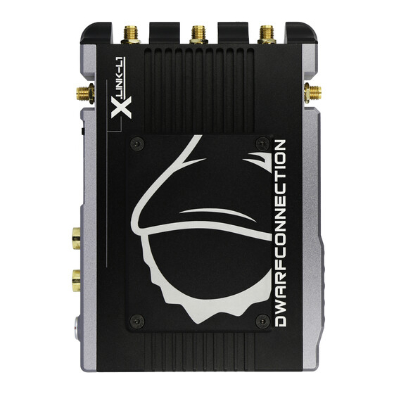
Product Description ULR1, LR2 and X.LINK-L1 Receiver 1) 1/4“ Tripod Mount 2) RSSI Status Display: Signal Strength 3) Menu Button 4) Control Buttons 5) OLED display 6) Power Switch 7) HDMI-OUT: HDMI Output (Type A Female Connector) 8) Dual SDI-OUT: 3G/HD/SD-SDI Output, (BNC Female Connector) 9) DC-IN: 7,2 –... -
Page 9: Operation
Scope of Delivery DC-LINK ULR1, DC-LINK-LR2 DC-X.LINK-L1 1x Transmitter 1x Receiver 1x Receiver 6x External antenna 9x External Antenna 1x D-Tap cable 4pin 2x D-Tap cable 4pin 1x Magic arm with 1/4“ screw 2x Power supply 4pin 1x Hotshoe Mount 1x Magic arm with 1/4“... -
Page 10: Antenna Positioning
Antenna Positioning Position the antennas on transmitter and receiver as shown in the illustration. This ensures the best possible RF performance. Install the transmitter and the receiver as high as possible (at least 2 meters above ground level) to maintain a good line-of-sight. During operation, try to keep the transmitter and the receiver at similar heights. -
Page 11: Features
Features Menu Navigation Use the MENU button to easily navigate through the sub menus of your DC-LINK device. Press several times until the referring indicator is flashing. Then use + and – to change the state and confirm with MENU. OLED Display The OLED Display shows all important information on the transmitter and the receiver. - Page 12 the corresponding section of this manual. Transmitter and receiver have to be set to the same channel to work. If several systems are used at the same time, do not use neighboring channels to avoid interferences. A maximum number of 4 systems can be used simultaneously. Master Channel Selection (for all MKII devices) All receivers on the same channel will react to channel changes of the trans- mitter and follow automatically.
- Page 13 press and hold the - button for 3 seconds. The frequency scanner is only availa- ble on the HDMI output. To leave DC-SCAN press and hold the - button again. When entering DC-SCAN from channel 0, it will also show you the antenna check.
- Page 14 Encryption (for all MKII devices) In encryption mode, the transmitter sends an encoded signal that only linked receivers can read, making it easy to protect confidential content that is not meant for everyone’s eyes. To activate encryption mode, press and hold the MENU button on your device to enter the encryption menu.
-
Page 15: Maintenance
Maintenance Please do not attempt to repair, modify or alter these devices under any circumstances. Clean the devices with a soft, clean, dry and lint-free cloth. Do not open the devices, they contain no user-serviceable parts. Storage The devices can be stored at temperatures between -20°C and 60°C. For long- term storage, please use the original transport case and avoid environmental conditions such as high humidity, dust, or excessively acidic or base surroundings. -
Page 16: Technical Specifications
TechnicalSpecifications Transmitter Receiver 1x SDI Input (BNC female) 2x SDI Output (BNC female) 1x SDI Output (BNC female) Connections 1x HDMI Input (Type A female) 1x HDMI Output (Type A female) 2x Antenna (RP-SMA male) 5x Antenna (RP-SMA male) 1x DC Input (4-pin female) 1x DC Input (4-pin female) Power 7,2 –... -
Page 17: U.s. Regulatory Information
U.S. Regulatory Information Please find regulatory information, certification and compliance marks at the bottom of your DC-LINK product. Regulatory Information: United States FCC Regulatory Compliance Note: This equipment has been tested and found to comply with the limits for a Class B digital device, pursuant to part 15 of the FCC Rules. These limits are designed to provide reasonable protection against harmful interference in a residential installation. - Page 18 Radio Frequency Exposure These devices meet the U.S. Federal Communications Commission‘s (FCC) requirements for exposure to radio waves and are designed and manufactured not to exceed the FCC‘s emission limits for exposure to radio frequency (RF) energy. To comply with FCC RF exposure compliance requirements, a distance of at least 25.5 cm should be maintained between the antennas of these de- vices and persons during device operation.
-
Page 19: Notes
Notes... - Page 20 Notes...
- Page 21 DwarfConnection GmbH & Co KG Münzfeld 51 4810 Gmunden AUSTRIA www.dwarfconnection.com...
Need help?
Do you have a question about the DC-LINK ULR1 and is the answer not in the manual?
Questions and answers