
Summary of Contents for Byond ResPlus C-20A CPAP
- Page 1 BEYOND ResPlus C-20A CPAP User Manual Please read this manual carefully before using this product...
- Page 2 User Manual The following document is the User Manual for the BEYOND ResPlus C-20A CPAP (“C-20A CPAP” or “the device”) manufactured by Hunan Beyond Medical Technology Co., Ltd. (hereafter, called “BEYOND Medical”). All the information contained in this document is the legal property...
-
Page 3: Table Of Contents
Contents 1. Introduction ..................1 1.1 Intended use ................1 1.2 Warnings ................... 1 1.3 Cautions ..................2 1.4 Contraindications ..............3 2. Model ....................4 3. Package Contents ................. 4 4. Device Components ................4 5. Device Symbols ................... 5 6. -
Page 4: Introduction
1. Introduction 1.1 Intended use The BEYOND ResPlus C-20A CPAP is designed for delivery of positive airway pressure to provide non-invasive ventilation for adult patients with respiratory insufficiency or obstructive sleep apnea (OSA) in home or hospital environment. Rx only: Federal law restricts this device to sale by or on the order of a licensed healthcare practitioner. -
Page 5: Cautions
Do not operate this device in the presence of nitrous oxide and oxygen. Keep away from toxic or hazardous steam. Do not use this device if the room temperature is higher than 35℃(95° F). If the ambient temperature of the room is higher than 35℃(95° F), the air flow from the device may rise to exceed 40℃(105°... -
Page 6: Contraindications
Do not immerse the device in liquid of any kind. Do not let any liquid enter into the device or into the filter near the air inlet. The condensate water can damage this device. Make sure that the device returns to room temperature before use. -
Page 7: Model
2. Model MaxPressure Working Model Type Main components (cmH2O) Mode Auto Host Humidifier H10 CPAP C-20A CPAP SpO2 Kit S10(optional) APAP 3. Package Contents Item Articles Quantity Remark Host Standard Humidifier Standard Tubing Standard Mask Standard Adapter Standard User Manual Standard Air Filter Standard... -
Page 8: Device Symbols
Dial Can be rotated in either direction or pressed to select. Mute Pressing this button turns off the voice alarm On/Off Button Pressing this button switches the device On or Off. Air Outlet This is the connection point for the tubing Humidifier Pressing this button separates the humidifier from the Separation Button... -
Page 9: Device Operation
Heat Warning Caution: Federal law restricts this device to sale by or on Rx Only the order of a licensed healthcare practitioner. 6. Device Operation 6.1 First Use 6.1.1 Place the device on a steady flat table where the settings are easy to reach and the information on the display can be clearly seen by the user. -
Page 10: Humidifier
Connect the power supply and the tubing as listed for the first use (see above). Connect the mask and the headgear according to the Mask User Manual (provided separately). 6.2.2 Adjust the Tubing Adjust the tubing to make sure the tubing can move freely when the user is in a deep sleep. -
Page 11: Humidifier Connection & Separation With The Host Unit
Humidifier Cap Key Water Checking Window Air Inlet Humidifier Connector Humidifier Separation Key 7.2 Humidifier Connection & Separation with the Host Unit 7.2.1 Connect with the host unit Fig.7.2.1a Before the connection Fig.7.2.1b After the connection Push the host unit and humidifier together to connect them to each other. A “click” sound will be heard when they are properly connected. -
Page 12: Using The Spo2 Kit
Fig.7.2.3a Fig.7.2.3b (2) Add water through the Air Inlet port on top of the water tank. Make sure the water level does not exceed the Max line. Fig.7.2.3c In winter months, be sure to add warm water, but no hotter than 35℃(95° F). Do not fill the water tank above the Max line. -
Page 13: Parameter Settings
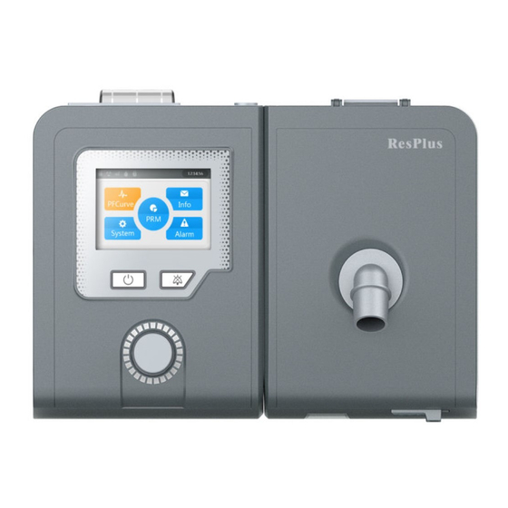
9. Parameter settings 9.1 Main Interface Screens Connect the device properly to mains power supply with power cord and power adapter. The screen displays the Main Interface screen will appear as shown in Fig. 9.1 below. Fig.9.1: C-20A Main Interface Users can set the desired humidifier levels and the Ramp time on the Main Interface;... -
Page 14: Pfcurve Interface
9.2 PFCurve interface Under main interface, rotate the “Dial” button to move the cursor onto the “PFCurve” indicator and press “Dial” button; the PFCurve Interface screen will appear on the display screen, as shown in Fig. 9.2 below. Fig.9.2: C-20A PFCurve Interface Screen 9.3 Parameter Setting Interface Under the main interface, rotate the "Dial"... - Page 15 Fig.9.3.b : Selected Status Screen Fig.9.3c : C-20A Parameter Setting Interface Screen 2 Parameter Range Description When the Auto ON is set to “ON”, the user can wear the mask and take 3 breaths in device’s Standby State. Auto ON ON/OFF The device will then automatically enter into the Working State.
-
Page 16: System Setting Interface
4-20 This setting sets the output pressure for the device. It *Press cmH2O can be set in increments of ± 0.5 cmH2O. CPAP Mode: The initial air pressure for the Ramp Function is equal to or less than the standard air pressure selected by the user. - Page 17 Fig.9.4a : System Setting Interface Screen 1 Fig.9.4b : System Setting Interface Screen 2 Fig.9.4c: System Setting Interface Screen (with Reset Dialogue Box active)
-
Page 18: Information Setting Interface
Parameter Setup range Description This parameter sets the device’s internal clock to track the time. This time will then be used to record Time h-m-s the application information for users. This setting needs to be checked frequently to ensure continued accuracy. -
Page 19: Epworth Interface
Fig.9.5b : C-20A Information Setting Interface 2 Parameter Setup range Description The time period over which the following 1/7/30/90/180/36 UseCycle information items are calculated. Unit is "day". The length of time that the device has been UseTime ------ connected to the power supply. Unit is “hour”. - Page 20 Fig.9.6a : Epworth Interface Screen 1 Fig.9.6b : Epworth Interface Screen 2 Fig.9.6c :Epworth Interface Screen 3...
-
Page 21: Prompt
10. Prompt Prompt Description Message If the power supply is disconnected while the device in the Working State , the device will provide a voice prompt via the Power buzzer for approximately 30 seconds. Pressing the "On/Off " Failure Button or re-powering the device will stop the voice prompts. After power is returned to the device, it will return to the normal state. -
Page 22: Cleaning
11.2 Cleaning 11.2.1 Cleaning the host and tubing To avoid the possibility of electrical shocks and damage to the electrical system, unplug the power cord from the host unit before cleaning the device. Clean the front panel and the outside of the case with a soft cloth that has been moistened with warm water or mild detergent. -
Page 23: Troubleshooting
headgear, tube and air filter should be replaced with new ones. Alternatively, users can also follow the procedures listed in Section 11.3 “Disinfection” 12. Troubleshooting The below table lists some of the common problems the device might have and provides possible solutions to those problems. If these suggestions do not solve these problems, please contact your healthcare provider directly. - Page 24 condense in the tube and towel or blanket over the collect in the mask. tube to maintain the temperature of the output air flow. Nasal, sinus, or ear Stop using the device Inflammation in sinus or pain immediately and contact middle ear.
-
Page 25: Specifications
The tube isn’t connected Reconnect the tubing and The device is properly. The mask or tubing ensure there are no leaks in excessively loud. may also be leaking. the tubing. The pressure can’t Turn off the Ramp feature, The Ramp feature is on. be set. - Page 26 <40℃(104° F) Output air flow temperature: The A-weighted sound pressure level does not exceed 30dBA, the A-weighted sound power level does not exceed 38dBA, when the device is working at the pressure of 10 Pressure Accuracy According to the pressure accuracy of ISO 80601-2-70:2015 standard. Pressure Range: •...
-
Page 27: Traveling With The Device
Not less than 10mg H Humidity output Measured conditions: Max flow, 35℃(95° F), 15% relative humidity. <1cmH O (with the flow rate of 60 Pressure drop caused by humidifier LPM) Leaking under maximum working <25mL/min (Together with the tubing) pressure: <20mL/kPa (Together with the Adaptability tubing) -
Page 28: Service
15. Service The device does not require any routine servicing. If you notice any unexplained changes in the performance of the device, if it is making unusual or harsh sounds, if it has been dropped or mishandled, if the enclosure is broken, or if water has entered the enclosure, you must discontinue use and contact your home healthcare provider. -
Page 29: Emc Requirements
Considering the life of components and safety, medical devices should not be used longer than 5 years. Expired products should be discarded according to corresponding local laws and regulations. DISCLAIMER OF IMPLIED WARRANTIES; LIMITATION OF REMEDIES CUSTOMER’S SOLE AND EXCLUSIVE REMEDY UNDER THIS LIMITED WARRANTY SHALL BE PRODUCT REPAIR OR REPLACEMENT AS PROVIDED HEREIN. - Page 30 Harmonic establishments and those directly connected emissions Class A to the public low-voltage power supply IEC61000-3-2 network that supplies buildings used for domestic purposes Voltage fluctuation Complies /flicker emissions IEC61000-3-3 Guidance and Manufacturer's Declaration - Electromagnetic Immunity This device is intended for use in the electromagnetic environment specified below. The user of the device should make sure that it is used in such an environment.
- Page 31 Power Power frequency magnetic frequency fields should be at levels (50/60Hz) characteristic of a typical 3A/m 3A/m magnetic field location in a typical IEC61000-4- hospital or home environment. Note: U is the a.c. mains voltage prior to application of the test level. Guidance and Manufacturer's Declaration - Electromagnetic Immunity This device is intended for use in the electromagnetic environment specified below.
-
Page 32: Manufacturer
considered. If the measured field strength in the location in which the device is used exceeds the applicable RF compliance level above, the device should be observed to verify normal operation. If abnormal performance is observed, additional measures may be necessary, such as re-orienting or relocating the device. -
Page 33: Agent
U.S Agent: United Source LLC Email: BEYOND@united-source.com Address: 1521 Concord Pike, Suite 301, Wilmington, DE, 19803, USA VersionNo.: U.S./20201218/A1...
Need help?
Do you have a question about the ResPlus C-20A CPAP and is the answer not in the manual?
Questions and answers
How do I change the pressure for a patient's CPAP C-20A
To change the pressure settings on a Byond ResPlus C-20A CPAP machine:
1. Rotate the "Dial" button to move the cursor onto the “Parameters” icon.
2. Press and hold the "Dial" button for 5 seconds to unlock the Parameter Setting Interface.
3. Adjust the *MinPress (minimum pressure) and *MaxPress (maximum pressure) settings in increments of ±0.5 cmH2O.
4. Press the "Dial" button to confirm the changes.
Note: Parameters marked with "*" can only be adjusted while the interface is unlocked.
This answer is automatically generated
Do you ned to have a card to access patient data?
How do you turn off the humidifier
Is the water tank for the humidifier dishwasher safe?