Table of Contents
Advertisement
Advertisement
Table of Contents
Troubleshooting

Summary of Contents for COBHAM AVIATOR 200S
- Page 1 AVIATOR 200S Installation Manual Cobham Public...
- Page 2 AVIATOR 200S System Installation Manual Document number: 98-145168-A Release date: 28 October 2020...
- Page 3 In the event of any discrepancies, the English version shall be the governing text. Thrane & Thrane A/S is trading as Cobham Aerospace & Communication. Manufacturer address COBHAM, 35 Rue de monthéry, 94563 RUNGIS Cedex (FRANCE) Copyright ©...
- Page 4 Record of revisions Rev. Description Release Date Initials Original document 28 October 2020...
-
Page 5: Table Of Contents
About this manual Purpose .............................1-1 Organization .........................1-1 Precautions: Warnings, Cautions and Notes ..........1-2 Chapter 2 Introduction General description ......................2-1 2.1.1 The AVIATOR 200S System ..................2-1 2.1.2 Maintenance interfaces (ACD) ..................2-7 2.1.3 Power supply input ......................2-7 2.1.4 Interface to the SCM ......................2-7 2.1.5 Interface to the HELGA ....................2-7... - Page 6 Recommended cable between the SCM and the CSDU ....... 4-30 Verifying the installation ..................4-30 Activation of airtime services ................4-30 4.6.1 ID numbers for the AVIATOR 200S system ............4-30 Chapter 5 Setup of the system Software upload ........................5-1 5.1.1...
- Page 7 Table of contents Chapter 6 Verification Basic check flow ........................6-1 6.1.1 Check procedures .......................6-1 Pre-Installation Check ....................6-2 Functional Test, on Ground ..................6-3 6.3.1 Before you start ........................6-3 6.3.2 Check list for functional test on ground ..............6-3 Interference Test ......................6-4 6.4.1 Introduction ..........................6-4 6.4.2 Test procedure ........................6-4...
- Page 8 Table of contents SCM-5055 Configuration Module ................A-4 Appendix B System messages BITE error codes .......................B-1 B.1.1 List of BITE error codes ....................B-1 Appendix C DO-160G specifications General DO-160 information ...................C-1 C.1.1 Certifying agency ........................C-1 C.1.2 Environmental Qualification Forms ................C-1 Compact Satellite Data Unit (CSDU) ..............C-2 Configuration Module (SCM) ...................C-5 HLD/Enhanced Low Gain Antenna (HELGA) ..........C-7 Appendix D...
-
Page 9: About This Manual
Chapter 1 About this manual Purpose The purpose of this manual is to provide information for installation of the AVIATOR 200S system. The information, drawings and wiring diagrams contained in this manual are Important intended as a reference for engineering planning only. The drawings and wiring diagrams contained herein do not represent any specific Supplemental Type Certificate (STC). -
Page 10: Precautions: Warnings, Cautions And Notes
LRU mating connectors. CAUTION! Do not use materials that are not equivalent to materials specified by Cobham. Materials that are not equivalent can cause damage to the equipment and can void the warranty. Weights and measurements Weights and measurements are in metric values (SI) with imperial metrics in parentheses. -
Page 11: Introduction
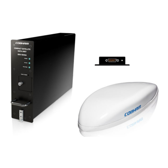
The AVIATOR 200S System System overview The AVIATOR 200S System is an Inmarsat aeronautical SATCOM system, which provides Inmarsat SwiftBroadband services and safety services (Class 4). It delivers secure ACARS services over a robust IP data link together with dual cockpit voice channels. The AVIATOR 200S System is a single-channel system for cockpit use and complies with ARINC Characteristic 781 Mark 3 Aviation Satellite Communication Systems. - Page 12 • SCM-5055 Compact SDU Configuration Module (SCM) • LGA-5005 HLD/Enhanced Low Gain Antenna (HELGA) The CSDU is the master of the AVIATOR 200S System and controls the associated units in the system. The SCM and the antenna are powered by the CSDU.
- Page 13 General description Compact Satellite Data Unit (CSDU) The AVIATOR 200S Compact Satellite Data Unit (CSDU) is a 2 MCU LRU with an ARINC 600 connector. It is a highly secure system with complete aircraft network segregation for the Aircraft Control Domain (ACD) over the Aircraft Information Service Domain (AISD).
- Page 14 1x Discrete input, ARINC 781, for LNA BITE (provisioned) 1x Input from LNA, hardware provisioned 1x Input from antenna, hardware provisioned 1x Cobham antenna control interface, hardware provisioned 1x DLNA interface, hardware provisioned 1x RF TX/RX interface, for HELGA Configuration...
- Page 15 General description Maintenance interfaces System function Interfaces BITE 1x ARINC 429 output for CFDS 1x ARINC 429 input for CFDS 1x Discrete ARINC 781 output, hardware provisioned for System Fail Data Loading 1x Ethernet for Data Loader A615A 1x Discrete input ARINC 781 for Data Loader Link A 1x ARINC 429 output for Data Loader A615 1x ARINC 429 input for Data Loader A615 Support...
- Page 16 • SCDU to display system messages (Information and BITE codes) • Headset connected to the audio control panel to make and answer calls Up to 3 SCDUs can be connected. System status and BITE messages of the AVIATOR 200S system can be displayed in the SCDU display.
-
Page 17: Maintenance Interfaces (Acd)
General description Configuration files for the AVIATOR 200S system The configuration files (Secure ORT and User ORT) for the AVIATOR 200S system are uploaded to the CSDU with an ARINC 615A (Ethernet) or ARINC 615-3 (ARINC 429) compliant data loader. Refer to the ORT Tool User Guide [9]. There are two configuration files: •... -
Page 18: Electrical Interfaces - Overview
3 x Status LED on Front Panel Figure 2-2: Electrical interfaces - overview The interfaces greyed out are disabled or not in use in the AVIATOR 200S Note software. This can be due to interfaces not being supported or reserved for future use. -
Page 19: Part Numbers
Part numbers Part numbers This installation manual is for the AVIATOR 200S system and is applicable to the type and part numbers below: Type number Part number Component name SDU-5045 405045-vvccc Compact Satellite Data Unit (CSDU) SCM-5055 405055-vvccc Compact SDU Configuration Module (SCM), external... -
Page 20: Equipment Drawings
Chapter 3 Equipment drawings This chapter has the following sections. • SDU-5045 Compact Satellite Data Unit • SCM-5055 SDU Configuration Module • LGA-5005 HLD/Enhanced Low Gain Antenna • CSDU tray • CSDU tray connector The following pages show copies of outline drawings of important system units relevant for an installation. -
Page 21: Sdu-5045 Compact Satellite Data Unit
SDU-5045 Compact Satellite Data Unit SDU-5045 Compact Satellite Data Unit Figure 3-1: Outline Drawing: CSDU Chapter 3: Equipment drawings 98-145168-A... -
Page 22: Scm-5055 Sdu Configuration Module
SCM-5055 SDU Configuration Module SCM-5055 SDU Configuration Module Figure 3-2: Outline drawing SCM-5055 (1/2) 98-145168-A Chapter 3: Equipment drawings... - Page 23 SCM-5055 SDU Configuration Module Figure 3-3: Outline drawing SCM-5055 (2/2) Chapter 3: Equipment drawings 98-145168-A...
-
Page 24: Lga-5005 Hld/Enhanced Low Gain Antenna
LGA-5005 HLD/Enhanced Low Gain Antenna LGA-5005 HLD/Enhanced Low Gain Antenna Figure 3-4: Outline Drawing: HELGA (1/2) 98-145168-A Chapter 3: Equipment drawings... - Page 25 LGA-5005 HLD/Enhanced Low Gain Antenna Figure 3-5: Outline Drawing: HELGA (2/2) Chapter 3: Equipment drawings 98-145168-A...
- Page 26 LGA-5005 HLD/Enhanced Low Gain Antenna 98-145168-A Chapter 3: Equipment drawings...
-
Page 27: Csdu Tray
CSDU tray CSDU tray Figure 3-6: Outline drawing: CSDU tray Chapter 3: Equipment drawings 98-145168-A... -
Page 28: Csdu Tray Connector
CSDU tray connector CSDU tray connector Figure 3-7: ARINC 600 tray connector 98-145168-A Chapter 3: Equipment drawings... -
Page 29: General Installation Information
Overview This chapter contains considerations and recommendations for the installation of the AVIATOR 200S System. Interconnect harness wiring and physical mounting must satisfy all applicable regulations. Also see the accompanying LGA-5005 HELGA Installation Manual [8] for the antenna, which is part of the AVIATOR 200S system. -
Page 30: Sdu-5045 Csdu
Power Supply BP5 +115 VAC Line (Hot) Aircraft ARINC 429 IRS/AHRS A429 A, MP06G BP1 +115 VAC Navigation outputs IRS/AHRS A429 B, MP06H Neutral (Cold) BP3 Chassis Ground Figure 4-1: AVIATOR 200S system (minimum, AC powered) Chapter 4: Installation 98-145168-A... - Page 31 Overview For optimum system performance you must follow some guidelines on where to install the components of the AVIATOR 200S system. Installation and placement details are included in this section. For information on requirements to cables refer to the individual sections in Electrical installation and wiring on page 4-6.
-
Page 32: Scm-5055 Scm
Mounting considerations 2. Mount according to Amphenol ARINC 600 Document SL-379-3. 3. Mount ground PIN to MP04G on ARINC 600 Connector Chassis Ground: ARINC 600 pin BP3 Amphenol contact part number: AC-781212-304. Fit to wire AWG12 & AWG14 Total max resistance: 25 mOhm. Shield from fluid drippage To fulfill DO-160G Waterproofness Cat. -
Page 33: Lga-5005 Helga
Place the antenna with unobstructed view to the satellite. The outline drawing is shown in Figure 3-4: Outline Drawing: HELGA (1/2). An AVIATOR 200S System can only be used with the LGA-5005 HELGA. WARNING! Keep a safety distance of minimum 60 cm (2 ft) to the antenna when the system is transmitting, unless the antenna manual or the specific system configuration presents different requirements. -
Page 34: Electrical Installation And Wiring
Electrical installation and wiring Electrical installation and wiring 4.3.1 Wiring symbols Throughout the wiring section these common symbols are used: Coax Shield Ground (fuselage) Twisted Twisted and shielded Each wiring drawing in this chapter only shows the connections referred to in Important that particular section. -
Page 35: Wiring - Overview
Electrical installation and wiring 4.3.2 Wiring – overview CSDU SDU-5045 Ethernet 1 from CSDU to EFB 1 TX+ Data from MCDU 1 MP01A A-429 input (A) TP03A (+TX) Ethernet 1 from CSDU to EFB 1 TX- Data from MCDU 1 A-429 input (B) MP01B TP04B (-TX) -
Page 36: To Wire The Csdu With Ac Input
Electrical installation and wiring 4.3.3 To wire the CSDU with AC input ARINC-781 compliant. The aircraft power bus provides the electric power required to operate the CSDU, and a chassis connection to the aircraft chassis and the installation tray. The +115 VAC power wire must include a circuit breaker capable of carrying the required current continuously under the required environmental conditions. - Page 37 Electrical installation and wiring Description of the CSDU power supply +115 VAC Power (BP1, BP5) The target line impedance should be as low as possible; 1 Ohm preferred maximum; should not exceed 4 Ohms. Required current capability for the Circuit Breaker: 99 W @ 90 VAC which equals 1.1 A at the required environmental conditions.
-
Page 38: To Wire The Scm
Electrical installation and wiring 4.3.4 To wire the SCM Wiring diagram The following drawing shows the wiring of the SCM to the CSDU. The SCM connector pin- out is compliant with ARINC-781. 10 meter Interconnecting Cable: Carlisle (Tensolite) P/N NF24Q100-01 100Base-T Ethernet Cable. 100ohm ±10%, 13pF/ft, AVG24 DB15 FEMALE (Rear view) -
Page 39: To Wire The Scdu 1, 2 And 3
4.2.4 for the maximum loss requirement at 1.6 GHz. Wiring diagram See Figure 4-1: AVIATOR 200S system (minimum, AC powered) for the wiring for an AVIATOR 200S System with the LGA-5005 HELGA For the requirements to RF cable see Recommended RF cables on page 4-29. -
Page 40: To Wire Cockpit Audio 1 And 2
Electrical installation and wiring Wiring diagram See Wiring – overview on page 4-7. Pins for CMU 1 and 2 CSDU pin Description MP07J Data to CMU 1 and 2. A. (A429 output) MP07K Data to CMU 1 and 2. B. (A429 output) MP03A Data from CMU 1. -
Page 41: To Wire Irs/Gnss
Electrical installation and wiring 4.3.9 To wire IRS/GNSS Wiring diagram See Wiring – overview on page 4-7. Pins for IRS/GNSS CSDU pin Description MP02A Data from primary IRS/GNSS A MP02B Data from primary IRS/GNSS B MP02J Data from secondary IRS A MP02K Data from secondary IRS B MP06J... -
Page 42: To Wire Airborne Data Loader
Electrical installation and wiring CSDU Pin Description MP06C Spare discrete input #3 MP07C Spare discrete input #4 MP07D WOW input1 MP08E Data loader link A. Discrete input MP08F TX mute input. Discrete input Description Various discrete interfaces are available, as listed here. 4.3.11 To wire airborne data loader ARINC-781 compliant. -
Page 43: To Wire Ethernet 1 (Aisd#1 Or Efb 1)
Electrical installation and wiring CSDU pin Description MP08J Data to CFDS A MP08K Data to CFDS B Description of the fault/health reporting The CSDU communicates Built-In Test Equipment (BITE) reporting to the aircraft Centralized Fault Display System (CFDS) or Central Maintenance Computer (CMC). 4.3.13 To wire Ethernet 1 (AISD#1 or EFB 1) ARINC-781 compliant. -
Page 44: To Wire Ethernet 3 (Adl In Acd)
Electrical installation and wiring Pins for Ethernet 11 (AISD#2 or EFB 2) CSDU pin Description TP03J Ethernet 11 from CSDU to User + (AISD#2) TP03K Ethernet 11 from User to CSDU + (AISD#2) TP04K Ethernet 11 from CSDU to User - (AISD#2) TP04J Ethernet 11 from User to CSDU - (AISD#2) Description of Ethernet 11 (AISD#2 or EFB 2) -
Page 45: To Wire Ethernet 5 (Acd #2)
Electrical installation and wiring CSDU pin Description MP 2T 4 Ethernet 4 from User to CSDU - Description of Ethernet 4 (ACD#1) This interface is software disabled and reserved for future use. • Ethernet Port Definition: Cockpit Priority Data 1 •... - Page 46 Electrical installation and wiring Micro USB Maintenance CSDU ID – Not used Figure 4-5: Wiring Maintenance PC via Micro USB Figure 4-6: Micro USB maintenance connector of the CSDU, face view of engaging end The following list shows the pins used for the Micro USB interface (Front connector on the CSDU).
- Page 47 Electrical installation and wiring maintenance interface on the front of the CSDU or via the AISD 1 / EFB 1 Ethernet interface). Figure 4-7: SDU-5045 Front plate The front panel status LEDs will display the following: • Steady red: A fault, which may degrade the system operation, is present in the CSDU. •...
-
Page 48: Csdu Arinc 600 Connector Block
Electrical installation and wiring 4.3.19 CSDU ARINC 600 connector block ARINC 600 connector drawing - overview Size 2 Shell receptacle Top Plug (TP): Pin 71 Insert arrangement 08 Receptacles A B C D E F G H J K 1 Size 1 Coax cavity 50 Size 22 sockets •... - Page 49 Electrical installation and wiring ARINC 600 connector drawings with functions The following drawing shows the top plug, middle plug and bottom plug of the SDU rear receptacle with pin functions. For wiring details of this connector see Electrical installation and wiring on page 4-6. The pins named No Connect are not connected to any electrical circuit inside the Note CSDU.
- Page 50 Electrical installation and wiring Call Call Data from Data from Ext. Reset Data from Data from Place/End SCM Power Place/End MCDU 1 MCDU 1 No Connect No Connect Discrete MCDU 2 MCDU 2 Discrete 15 V Discrete Input Input 1 Input 2 Data from Data from...
- Page 51 Electrical installation and wiring 115V COLD No Connect No Connect No Connect No Connect Chassis GROUND No Connect 115v No No Connect Connect Figure 4-11: CSDU Bottom Plug in rear receptacle with pin functions 98-145168-A Chapter 4: Installation 4-23...
- Page 52 Electrical installation and wiring Pin-out for CSDU rear receptacle (top plug) Pin name Pin name TP04F No Connect TP71 RF TX or RX/TX, to HELGA/HLD TP04G No Connect TP01A No connect TP04H Empty Cavity TP01B No connect TP04J Ethernet 11 from User to CSDU- (AISD#2) TP01C ATE pin 3 (Spare GND) TP04K...
- Page 53 Electrical installation and wiring Pin-out for CSDU rear receptacle (middle plug) Pin name and description Pin name and description MP04B Cockpit audio input 1 Low MP01A Data from MCDU 1 A MP04C Cockpit Voice Go Ahead Chime Reset MP01B Data from MCDU 1 B MP04D SDU Data to SCM B MP01C...
- Page 54 Electrical installation and wiring Pin name and description Pin name and description MP10D No Connect MP07A AES ID input A MP10E No Connect MP07B AES ID input B MP10F No Connect MP07C Spare discrete input #4 MP10G No Connect MP07D WOW input 1 MP10H No Connect...
- Page 55 Electrical installation and wiring Pin-out for CSDU rear receptacle (bottom plug) Pin name and description 115 V COLD. 115 VAC power return 28 V HOT. 28 VDC power (No Connect - Provision only) Chassis Ground 28 V GND. 28 VDC power return (No Connect - Provision only) 115V HOT.
-
Page 56: Recommended Cables
Recommended cables Recommended cables 4.4.1 Introduction This section lists recommended cables and allowed cable lengths for the cables in the AVIATOR 200S system. For specific cable requirements see the applicable section in 4.3 Electrical Important installation and wiring. 4.4.2 Allowed cable lengths for power cables... -
Page 57: Recommended Power Cables
Recommended cables 4.4.3 Recommended power cables The cable types must meet the following standards: • M27500 for shielded wire. • M22759 for single wire. AC Power: Single unshielded wire 18 AWG (Hot) & 12 AWG (Cold) Manufacturer: Carlisle (Thermax) MIL-DTL-22759/86-18 Manufacturer: Carlisle (Thermax) MIL-DTL-22759/86-12 4.4.4 Recommended RF cables... -
Page 58: Recommended Cable Between The Scm And The Csdu
Verifying the installation You must perform certain check procedures during and after installation of the AVIATOR 200S system. The first check procedures are performed after wiring, but before inserting LRUs.For information on the required and recommended check procedures, refer to Verification on page 6-1. - Page 59 Activation of airtime services SwiftBroadband USIM cards The AVIATOR 200S system is delivered with four USIM cards permanently installed in the SCM. The USIM cards are pre-authenticated by Inmarsat and identified by their unique IMSI (International Mobile Subscriber Identity) number. The length of the IMSI is 15 digits.
- Page 60 Activation of airtime services 4-32 Chapter 4: Installation 98-145168-A...
-
Page 61: Setup Of The System
Chapter 5 Setup of the system This chapter has the following sections: • Software upload • SATCOM system ready for use Line of sight Note You can configure the system while the aircraft is in the hangar. Note that you cannot typically check the satellite communication while the aircraft is still in the hangar. -
Page 62: Uploading Software
2. Upload the files using a compliant data loader, see the data loader’s instruction manual. SATCOM system ready for use Having installed the AVIATOR 200S system and loaded the necessary software, verify that the system is fully operational. Line of sight during operation! -
Page 63: Chapter 6 Verification
4. Interference Test. After the functional test, make an interference test. This test is to verify that transmission from the AVIATOR 200S system has no effect on the avionics of the aircraft, particularly navigation equipment. Refer to Interference Test on page 6-4. -
Page 64: Pre-Installation Check
Pre-Installation Check Pre-Installation Check It is recommended to check the installation before inserting LRUs. The following list provides some of the most important issues, but other additional checks may be relevant for the specific installation. Reference Value/ Item Description of Check Section Comment Mounting trays... -
Page 65: Functional Test, On Ground
Check that the Fail/Pass LED is green Check that the Logon LED is green MCDU Make an aircraft to ground call AVIATOR 200S headsets #1 to User Manual Make a ground to aircraft call AVIATOR 200S User Manual Ethernet... -
Page 66: Interference Test
It is recommended to do an interference test to ensure that transmission from the AVIATOR 200S system does not influence any of the primary avionics on the aircraft. This test is not a replacement for any EMC tests in connection with e.g. an Important STC (Supplemental Type Certificate), TC (Type Certificate) or Field Approval. -
Page 67: Functional Test, Airborne
Item Description of Check Reference Comment MCDU Make an air to ground call and AVIATOR 200S headsets #1 keep it up during a 360 turn. User Manual to #2 Make a ground to air call AVIATOR 200S User Manual... -
Page 68: Chapter 7 Maintenance And Troubleshooting
Maintenance requirements and instructions for continued airworthiness of the Cobham SATCOM units in the AVIATOR 200S System are defined here. The AVIATOR 200S System (CSDU, SCM and HELGA) requires no periodic scheduled servicing tasks. When replacing the CSDU, it is important to leave the SCM installed in the aircraft, Note because the SCM contains the aircraft-specific configuration data. -
Page 69: Maintenance Instructions
7.1.2 Maintenance instructions Documentation Maintenance information for the AVIATOR 200S System is contained in this manual. Place the wiring diagram information in this manual in the aircraft operator's appropriate aircraft wiring diagram manuals. Inoperative units If a system component is inoperative, remove or replace the unit. - Page 70 Continued Airworthiness None required HELGA None required Table 7-1: Periodic scheduled maintenance tasks The recommended periodic scheduled inspection tasks to be added to the aircraft operator's appropriate aircraft maintenance program are as follows: CSDU None required None required HELGA None required Table 7-2: Periodic scheduled inspection tasks The recommended periodic scheduled preventative maintenance tasks to be added to the aircraft operator's appropriate aircraft maintenance program are as follows:...
-
Page 71: Helpdesk
Helpdesk Helpdesk If this manual does not provide the remedies to solve your problem, you may want to contact your Airtime Provider or your local distributor. 7.2.1 System support If you need assistance with problems caused by the CSDU, SCM or HELGA, call a distributor in your area. -
Page 72: Software Update
See Software upload in chapter 5. To exchange an LRU This document describes the procedures for removal and re-installation of the AVIATOR 200S LRUs: • CSDU (405045-vvccc). • SCM (405055-vvccc) For the procedure of removal and re-installation of the HELGA (LGA-5005) see the HELGA installation manual [8]. -
Page 73: Removal And Re-Installation Of The Scm (Scm-5055)
To exchange an LRU 7.4.5 Removal and re-installation of the SCM (SCM-5055) 1. Ensure that power is removed from the SATCOM system before removing the SCM. 2. Release the screw-locks on the D-sub connector and remove the 15 pin D-sub connector from the SCM. -
Page 74: Troubleshooting
CSDU. Also, during operation a Continuous Monitoring BITE function is performed. Each LRU in the AVIATOR 200S system has its own BITE function but they are all controlled and monitored by the CSDU in the system. -
Page 75: Status Signalling With Leds
Troubleshooting 7.5.2 Status signalling with LEDs LEDs on CSDU During the power-up procedure all LEDs on the front plate are orange. If all 3 LEDs on the front stay orange after power up, check the AC supply of the CSDU. If the wiring is good, the CSDU software may be corrupted. -
Page 76: Initial Troubleshooting
7.5.3 Initial troubleshooting Overview This section describes an initial check of the primary functions of the AVIATOR 200S System, and provides some guidelines for troubleshooting, if one of the checks should fail. Means available for troubleshooting The following means are available for troubleshooting: •... -
Page 77: Returning Units For Repair
Should you need to send the product for repair, please read the below information before packing the product. The shipping carton has been carefully designed to protect the AVIATOR 200S and its accessories during shipment. This carton and its associated packing material should be used when repacking for shipment. -
Page 78: Disposal Of Electrical And Electronic Equipment
Disposal of electrical and electronic equipment Disposal of electrical and electronic equipment Old electrical and electronic equipment marked with this symbol can contain substances hazardous to human beings and the environment. Never dispose these items together with unsorted municipal waste (household waste). In order to protect the environment and ensure the correct recycling of old equipment as well as the re-utilization of individual components, use either public collection or private collection by the local distributor of old electrical and electronic... -
Page 79: Appendix A Equipment Specifications
Appendix A Equipment specifications Introduction This appendix has the following sections: • SDU-5045 Compact Satellite Data Unit • SCM-5055 Configuration Module Important note! The information, drawings, and wiring diagrams contained in this manual are intended as a reference for engineering planning only. It is the installer’s responsibility to compose installation drawings specific to the aircraft. - Page 80 Power provided for HELGA: 51 W (AVIATOR 200S) Power provided for SCM: 4.5 W Power consumption as Class 4 AC: <100 W system AVIATOR 200S including SCM and HELGA Maximum heat dissipation <50 W Connectors Rear: ARINC 600 Attachment 11 Front: micro USB (for maintenance).
- Page 81 SDU-5045 Compact Satellite Data Unit Characteristics Specification Ground survival temperature -55° to +85° C Shelf life Max. 7 years at max. 35° C Maximum resistance, AC input < 1.0 Ohm Altitude For installation in non-pressurized locations: Max. 55000 ft (Cat-F2) Decompression For installation in pressurized locations: 55000 ft (Cat.
-
Page 82: Scm-5055 Configuration Module
SCM-5055 Configuration Module SCM-5055 Configuration Module Characteristics Specification Dimensions (L x W x H) 114.00 mm x 101.60 mm x 25.40 mm (4.49" x 4.00" x 1.00") Weight 200 ± 30 g • Non-controlled temperature locations with Mounting convection airflow cooling •... -
Page 83: Appendix B System Messages
System messages This appendix has the following sections: • BITE error codes The AVIATOR 200S system shows system messages in connected display units (e.g. MCDU) or in the security and system log files of the CSDU when extracted in maintenance-allowed mode. - Page 84 BITE error codes Fault Fault message FDCE type Failure cause Consequences on the system message subject code MCDU1 SATCOM system receives an ARINC MCDU1 is unusable for Loss of (2CA1) 429 message from MCDU1 with a control/status of the SATCOM SSM set to NCD/FW/FT system.
- Page 85 BITE error codes Fault Fault message FDCE type Failure cause Consequences on the system message subject code MCDU2(2CA2 SATCOM system receives an ARINC MCDU2 is unusable for Loss of )/SDU1(5RV1) 429 message from MCDU2 with a control/status of the SATCOM /WRG SSM set to Silent system...
- Page 86 BITE error codes Fault Fault message FDCE type Failure cause Consequences on the system message subject code RMP1(3RN1)/ SATCOM system receives an ARINC RMP1 is unusable for control/status Loss of SDU1(5RV1)/ 429 message from RMP1 with a SSM of the SATCOM system set to Silent RMP2(3RN2)/ SATCOM system receives an ARINC...
- Page 87 BITE error codes Fault Fault message FDCE type Failure cause Consequences on the system message subject code ANTENNA- The HELGA is overheated Probable loss of communications SATCOM LOW GAIN Fault (46RV1)/ OVER TEMPERA WRG: CONFIG Configuration HPP Parity error, Probable loss of communications SATCOM Configuration HPP combination not Fault...
- Page 88 BITE error codes Fault Fault message FDCE type Failure cause Consequences on the system message subject code SDU1(5RV1)/ Discrete Output failure No light indication of incomming No light call on channel 2 or No light indication indication of incomming call on channel 1 incoming call on...
-
Page 89: General Do-160 Information
C.1.1 Certifying agency Approval of the installation of the AVIATOR 200S system is not authorized by this installation manual. Acceptance for the installation and use of the AVIATOR 200S system and its associated components must be obtained through the appropriate offices of the FAA or other certifying agency. - Page 90 Compact Satellite Data Unit (CSDU) Compact Satellite Data Unit (CSDU) Part Number: SDU-5045 DO160 G section Category and Environmental variable requirements (Unless otherwise specified) Temperature and Altitude [(A2F2)Z] Ground Survival Low Temperature Test - 4.5.1 55°C Short-Time Operating Low Temperature 4.5.1 Test -40°C Operating Low Temperature Test -40°C...
- Page 91 Compact Satellite Data Unit (CSDU) DO160 G section Category and Environmental variable requirements (Unless otherwise specified) High-Level, Short Duration Vibration H(R) Explosion Atmosphere Waterproofness Fluids Susceptibility Sand & Dust Fungus Resistance Salt Fog Magnetic Effect Power Input A(WF)HLPI Voltage Spike Audio Frequency Conducted Susceptibility AC Power 18.3.2...
- Page 92 Compact Satellite Data Unit (CSDU) DO160 G section Category and Environmental variable requirements (Unless otherwise specified) Icing Electrostatic Discharge Fire, Flammability Federal Aviation Regulation FAR 25.853(a) & Appendix F, part I, §(a)(1)(ii) FAR 25.853(a) & Appendix F, part I, §(a)(1)(v) FAR 25.869 (a)(1) &...
- Page 93 Configuration Module (SCM) Configuration Module (SCM) Part Number: SCM-5055 DO160 G section Category and Environmental variable requirements (Unless otherwise specified) Temperature and Altitude Ground Survival Low Temperature Test - 4.5.1 55°C Short-Time Operating Low Temperature 4.5.1 Test -40°C Operating Low Temperature Test -40°C 4.5.2 Ground Survival High Temperature Test 4.5.3...
- Page 94 Configuration Module (SCM) DO160 G section Category and Environmental variable requirements (Unless otherwise specified) Bench Handling Shocks MIL-STD 810G, Method 516.6, Proc. VI Vibration Standard Random Vibration S(B3) High-Level, Short Duration Vibration H(R) Explosion Atmosphere Waterproofness Fluids Susceptibility Sand & Dust Fungus Resistance Salt Fog Magnetic Effect...
-
Page 95: Hld/Enhanced Low Gain Antenna (Helga
HLD/Enhanced Low Gain Antenna (HELGA) DO160 G section Category and Environmental variable requirements (Unless otherwise specified) Fire, Flammability (DO-160) Federal Aviation Regulation FAR 25.853(a) & Appendix F, part I, §(a)(1){ii) FAR 25.853(a) & Appendix F, part I, §(a)(1)(v) FAR 25.869 (a)(1) & Appendix F part I Table C-2: Common environmental conditions and tests (DO160G) for SCM (Continued) a. -
Page 96: Appendix D References
ARINC 429P1-19 Digital Information Transfer System (DITS), Part 1, Functional Description, Electrical Interfaces, Label Assignments and Word Formats, January 22, 2019 Other references AVIATOR 200S User Manual (98-158752). LGA-5005 HELGA Installation Manual (98-152675) ORT Tool User Guide (99-168498) [10] AVIATOR Operational User Guidance (99-157303) -
Page 97: Glossary
Glossary Glossary Aeronautical Administrative Communications ACARS Aircraft Communications Addressing And Reporting System ACAS Aircraft Collision Avoidance System.. Aircraft Control Domain Audio Control Panel Automatic Direction Finder. A navigation receiver based on the AM radio band. A very simple device which literally points towards the station that is tuned in. Airborne Data Loader ADS-C Automatic Dependent Surveillance - Contract... - Page 98 Glossary ICAO International Civil Aviation Organization Instrument Landing System. A system of tightly focused transmitters located at the end of a runway that provides flight guidance information to flight crews. IMSI International Mobile Subscriber Identity IPSEC Internet Protocol Security Low Gain Antenna Line Replaceable Unit.
-
Page 99: Index
Index Index contact , -ii address , 1-1 about this manual , 7-4 contact information activation , 6-1, 7-1 Continued Airworthiness , 4-31 SIM card address , -ii manufacturer , 7-2 , 4-30 defect units airtime services , 6-1, 7-1 discrete signals Airworthiness, Continued , 4-29... - Page 100 Index location SCM cable , 4-4 , 4-30 SDU temperature controlled data to and from CSDU , 4-30 Logon LED power source, power return , 7-8 , 4-30 on SDU recommended , C-2 DO-160 form , C-2 Environmental Qualification Form Maintenance connector , 4-4 location in aircraft...
- Page 101 98-145168-A www.cobham.com/satcom Cobham Public...
Need help?
Do you have a question about the AVIATOR 200S and is the answer not in the manual?
Questions and answers