
Related Manuals for SimCom SIM7022-EVB


Summary of Contents for SimCom SIM7022-EVB
- Page 1 SIM7022-EVB User Guide NB Module SIMCom Wireless Solutions Limited. SIMCom Headquarters Building, Building 3, No. 289 Linhong Road Changning District, Shanghai P.R.China Tel: 86-21-31575100 support@simcom.com www.simcom.com...
- Page 2 PATENT , A UTILITY MODEL OR DESIGN. ALL SPECIFICATION SUPPLIED HEREIN ARE SUBJECT TO CHANGE WITHOUT NOTICE AT ANY TIME. SIMCom Wireless Solutions Limited SIMCom Headquarters Building, Building 3, No. 289 Linhong Road, Changning District, Shanghai P.R. China Tel: +86 21 31575100 Email: simcom@simcom.com...
- Page 3 SIM7022-EVB User Guide V1.00 Version History Date Version Description of change Author 2021.07.21 1.00 Released Yanping Yang 3 / 33 www.simcom.com...
-
Page 4: Table Of Contents
SIM7022-EVB User Guide V1.00 Contents Introduction..............................7 1.1 Features Overview............................7 1.2 SIM7022 EVB Top and Bottom View......................8 1.3 SIM7022 Evaluation Kit..........................10 Interface Introduction..........................12 2.1 Power Supply..............................12 2.1.1 Power Supply..........................12 2.1.2 Separate Power Supply....................... 13 2.2 (U)SIM card Interface............................ 15 2.3 UART Interface............................... - Page 5 SIM7022-EVB User Guide V1.00 Table Index Table 1:Main features ..............................7 Table 2: Label information description......................... 9 Table 3: EVB Kit................................11 Table 4: EVB Kit................................11 Table 5: Interface introduction............................. 12 Table 6: (U)SIM card interface pin definition (J102)....................17 Table 7: micro USB interface pin definition (J103)....................18 Table 8: Status indicator light description........................19...
- Page 6 SIM7022-EVB User Guide V1.00 Figure Index Feature 1 : SIM7022 EVB top view..........................8 Feature 2 :SIM7022 EVB bottom view ........................9 Feature 3 : SIM7022 Evaluation kit..........................10 Feature 4 : EVBPower supply block diagram......................13 Feature 5 : EVB power interface..........................13 Feature 6 : Module power supply reference design....................
-
Page 7: Introduction
1 Introduction The purpose of this article is to introduce the interface and usage of the development kit. Based on the SIMCom development kit, developers will quickly become familiar with and verify the software functions of the module. 1.1 Features Overview The main features of SIM7022 EVB are shown in the table below. -
Page 8: Sim7022 Evb Top And Bottom View
SIM7022-EVB User Guide V1.00 1.2 SIM7022 EVB Top and Bottom View Feature 1: SIM7022 EVB top view 8 / 33 www.simcom.com... - Page 9 SIM7022-EVB User Guide V1.00 Feature 2:SIM7022 EVB bottom view Table 2: Label information description Label information Description SIM7022 Module Main serial port, used for AT commands and firmware upgrade DBG serial port, used for software LOG capture Power supply switch...
-
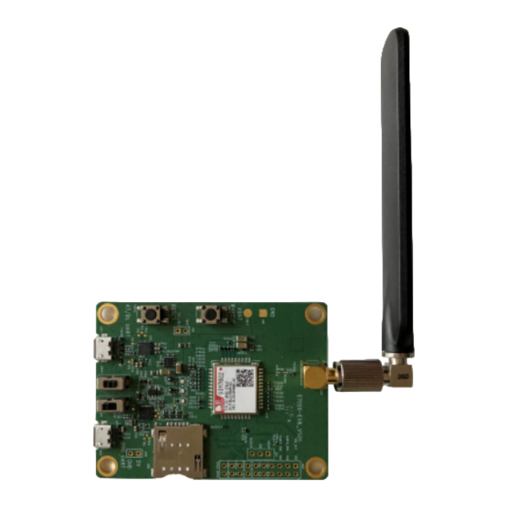
Page 10: Sim7022 Evaluation Kit
SIM7022-EVB User Guide V1.00 ※ Note 1. The SIM card of the SIM7022 EVB is shown as the position "J" in the rendering. The module does not support the hot-swappable function. Please insert the SIM card before turning on the module, otherwise the SIM card will not be recognized successfully. - Page 11 SIM7022-EVB User Guide V1.00 Table 3: EVB Kit EVB Kit Description quantity SIM7022 EVB EVB board GSM\WCDMA \LTE antenna GSM\WCDMA \LTE antenna MICRO USB data cable MICRO USB data cable To ensure that the module can be used normally, it is recommended to use the correct kit model. The part numbers of SIM7022 EVB kit are shown in the table below.
-
Page 12: Interface Introduction
SIM7022-EVB User Guide V1.00 2 Interface Introduction The interface of SIM7022 EVB is shown in the table below. Table 5: Interface introduction Function Reference number Description (U)SIM J102 (U)SIM card interface J103 is used for AT command communication, J103 data transmission and firmware upgrade... -
Page 13: Separate Power Supply
SIM7022-EVB User Guide V1.00 Feature 4: EVBPower supply block diagram Feature 5: EVB power interface 2.1.2Separate Power Supply The module power supply reference design is shown in the figure below. 13 / 33 www.simcom.com... - Page 14 SIM7022-EVB User Guide V1.00 Feature 6: Module power supply reference design The test points of VBAT and GND of the module are shown in the figure below. If the module needs to be powered separately, the resistance of R112 should be removed first, and then the VBAT and GND test points should be externally supplied with power.
-
Page 15: U)Sim Card Interface
SIM7022-EVB User Guide V1.00 Feature 7: Module power supply separately (VBAT GND) ※ Note 1. The power supply range of the module is 2.2~4.2V, and the recommended power supply voltage is 3.3V. When the power supply voltage is lower than 3V, the radio frequency can work and the performance of a single index may not meet the 3GPP standard. - Page 16 SIM7022-EVB User Guide V1.00 Featue 9: (U)SIM card interface pin definition (J102) 16 / 33 www.simcom.com...
-
Page 17: Uart Interface
SIM7022-EVB User Guide V1.00 Table 6: (U)SIM card interface pin definition (J102) Pin number Pin name Describe (U)SIM power supply (U)SIM reset signal (U)SIM clock signal (U)SIM detect signal Float (U)SIM duplex data line 2.3 UART Interface SIM7022 EVB provides two UART interfaces (J103, J104) by USB to UART. J103 is used as the main serial port for AT commands, data transmission and firmware upgrade, and J104 is used as DEBUG debugging serial port for software DEBUG debugging. -
Page 18: Status Indicator Light
SIM7022-EVB User Guide V1.00 Feature 10: USB to UART reference design The pin definition of the Micro USB interface is shown in the figure below. Feature 11: micro USB interface pin definition (J103) Table 7: micro USB interface pin definition (J103) -
Page 19: Switches And Buttons
SIM7022-EVB User Guide V1.00 Feature 12: LED status indicator light (LED101、LED102、LED103) Table 8: Status indicator light description LEDs number LEDs colour Description LED101 Blue Module network status indicator light LED102 VBAT power supply indicator light LED103 Blue Module power-on status indicator light 2.5 Switches and Buttons...
Need help?
Do you have a question about the SIM7022-EVB and is the answer not in the manual?
Questions and answers