
Summary of Contents for Braun Group ES-SVC Series
- Page 1 ES-SVC SERIES THREE PHASE SERVO MOTOR TYPE AUTOMATIC VOLTAGE REGULATOR USERS MANUAL (Version 1.0) Please read this manual carefully before installing or using this machine!
-
Page 2: Table Of Contents
Content 1. SAFETY INSTRUCTIONS 1.1 Human Safety.................1 1.2 Installation and Operation...............1 1.3 When Input Comes from Generator ..........1 2. SPECIFICATION 2.1 Schematic of Voltage regulator ............2 2.2 Features..................3 2.3 MAIN Specification .................3 3. FAMILIAR WITH THE REGULATOR 3.1 Exterior View ..................5 3.2 Display Panel .................6 3.3 Internal View...................7 4 PRODUCT EXAMINATION... -
Page 3: Safety Instructions
1. SAFETY INSTRUCTIONS The following instructions are related to human safety, please read them carefully! 1.1 Human Safety There is high voltage inside the running voltage regulator, in order to avoid electric shock, do not open the voltage regulator or take off the input wires and output wires. The connection wires must be laid reasonable. -
Page 4: Specification
2. SPECIFICATION 2.1 Schematic of Voltage Regulator (SVC-10K, SVC-15K, SVC-20K, SVC-30K) (SVC-45K, SVC-60K, SVC-80K, SVC-100K) QF: AIR BREAKER QS:MANUAL BYPASS SWITCH F: SURGE PROTECTION DEVICE KM: CONTACTOR T1J2.T3: SERIES TRANSFORMER TP1, TP2, TP3: VARIABLEAUTOTRANSFORMER M1, M2, M3: SERVO MOTOR TA1JA2.TA3: CURRENT TRANSFORMER... -
Page 5: Features
2.2 Features High Efficiency Using high purity oxygen-free copper wire for the windings, and high magnetic density silicon-steel plate for the cores, the transformer has very low idle power consumption, and the temperature rise is slow. 100% Unbalanced Loading Capability Between Three Phases Using the independent regulating for each phase, so that it can handle the 0-100% unbalanced loads between three phases. - Page 6 PROTECTION AND ALARM Output Under Voltage Output cutoff by contactor + "L" in display + Buzzer beeping Output Over Voltage Output cutoff by contactor + "H" in display + Buzzer beeping Overload Output cutoff by contactor + "F" in display + Buzzer beeping Over Temperature Output cutoff by contactor + "C"...
-
Page 7: Familiar With The Regulator
3. FAMILIAR WITH THE VOLTAGE REGULATOR 3.1 External View DISPLAY PANEL LOCK AIR BREAKER CASTER COOLING HOLE COOLING FAN... -
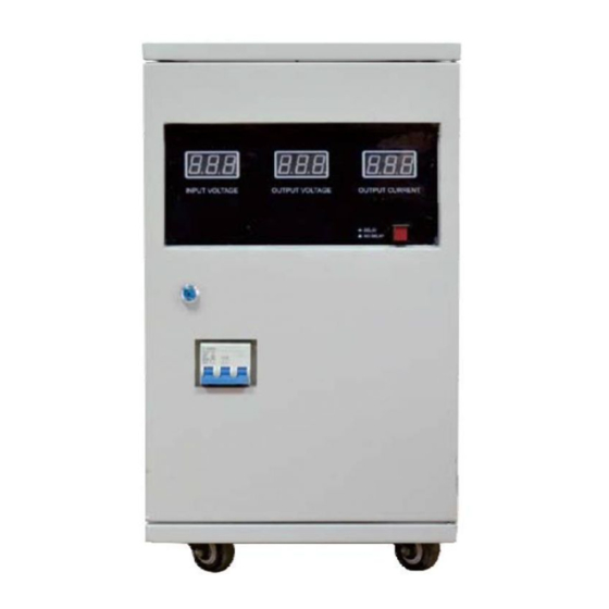
Page 8: Display Panel
3.2 Display Panel DISPLAY OF PHASE A (AB) DISPLAY OF PHASE B (BC) DISPLAY OF PHASE C (CA) "INPUT VOLTAGE" INDICATOR "OUTPUT VOLTAGE" INDICATOR "OUTPUT CURRENT" INDICATOR SWITCH BUTTON OF "INPUT AND OUTPUT VOLTAGE" "PHASE VOLTAGE" INDICATOR "LINE VOLTAGE" INDICATOR SWITCH BUTTON OF "PHASE AND LINE VOLTAGE"... -
Page 9: Internal View
3.3 Internal View MAIN BOARD MANUAL BYPASS SWITCH INPUT AIR BREAKER (MAINS SWITCH) REPLACEABLE SPD (OPTIONAL) CONTACTOR INPUTTERMINAL BLOCK OUTPUT TERMINAL BLOCK EARTH CABLE TERMINAL CABLE HOLDER... -
Page 10: Product Examination
4. PRODUCT EXAMINATION The voltage regulator is 100% tested before shipment. Check if it has been damaged after unpacking it, according to the follow steps: 4.1 Packing Contents Delivered pack includes: Voltage Regulator 1 set User's Manual 1 piece Warranty Card 1 piece 1 pair 4.2 Visual Observation... -
Page 11: Wiring Connection
• Place voltage regulator in a • Operation temperature • Keep away from well ventilated place, keep away -5°C - +45°C, humidity 0-90%, corrosive at least 10cm from the wall. non-condensing gas or fluid 6. WIRING CONNECTION 6.1 Wiring Precautions Please obey the laws, regulations of electrical safety in your country/area when choosing the wires and doing the wiring connection. -
Page 12: Operation
7. OPERATION 7.1 Switch On The Voltage Re g ul a t o r Make sure all the loads connected to the voltage regulator are switched off. Make sure the MANUAL BYPASS SWITCH is on the "AVR" (or "II") position. Put the INPUT AIR BREAKER to "ON"... -
Page 13: Alarm And Protection
8. ALARM AND PROTECTION 8.1. Overload Protection When load is <120%, the voltage regulator won't give alarm and protection. Once the load is over 120%, the buzzer will beep once per 2 seconds, in the same time, the countdown time for output cutoff will be shown in the display. Once the countdown is finished, the output will be cut off by contactor, in the same time, symbol "F"... -
Page 14: Maintenance
9. MAINTENANCE The voltage regulator is basically maintenance free! But regular check and maintenance can extend its life span. 9.1. Preventive Method. Do not put any liquid on top of the voltage regulator. Try to install the voltage regulator in a clean place, avoid much dust, sandy area. 9.2. -
Page 15: Annex I: Troubleshooting
ANNEX I: TROUBLESHOOTING Faulty Reason/How to Check What to do Input air breaker Heavily overloaded. Reduce the load to its rated capacity. trips off. The load is short circuit. Remove the load. Air breaker is faulty. Contact authorized dealer or manufacturer. Contactor trips off.
Need help?
Do you have a question about the ES-SVC Series and is the answer not in the manual?
Questions and answers