Table of Contents
Advertisement
Quick Links
Advertisement
Table of Contents

Subscribe to Our Youtube Channel
Related Manuals for LEM IST ULTRASTAB

Summary of Contents for LEM IST ULTRASTAB
- Page 1 IST ULTRASTAB USER GUIDE N° 99.92.98.000.0 5October2021/Version 8 Page 1 /14...
-
Page 2: Table Of Contents
FIGURE 7: Status/Interlock port wiring ....................... 11 FIGURE 8: Pinout for 15-pin status connector .................... 12 FIGURE 9: IST ULTRASTAB in a typical 3-channel current output application ......... 13 LIST OF TABLES TABLE 1: IT/ITN/IN ULTRASTAB compatibility chart................... 6 TABLE 2: Shielded connection cables ...................... -
Page 3: Introduction
1 INTRODUCTION Congratulations with your purchase of LEM IST ULTRASTAB. The IST ULTRASTAB unit serves as power supply and signal processing unit for up to 6 individual LEM high precision current transducers. It ensures that the extremely high precision and low noise offered by the transducers is preserved and made available in a convenient and user-friendly unit. -
Page 4: Warranty Statement
3 WARRANTY STATEMENT 5October2021/Version 8 Page 4 /14... -
Page 5: Technical Specifications
4 TECHNICAL SPECIFICATIONS Electrical Data – MAINS INPUT Mains Input 100 ... 240 V RMS, 50/60 Hz IEC-type dual-fused inlet socket Fuses 2.5 At / 240 V RMS Power consumption All channels driven at max. 1 A RMS < 150 W secondary output current Electrical data –... -
Page 6: System Description
Depending on the transducer’s type and applied primary current (DC or AC), the IST ULTRASTAB can drive up to 6 channels at a total consumption of maximum 125 W. -
Page 7: Front Panel
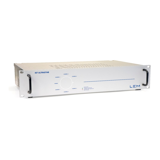
5.1 FRONT PANEL The front panel includes indicators for each transducer channel. FIGURE 1: An overview of the front panel, with a close-up of the indicator panel 5.2 INDICATOR PANEL The illuminated indicator panel has seven fields that are lit in the following modes: POWER: Green light - Mains power is applied. -
Page 8: Back Panel
5.3 BACK PANEL The IST ULTRASTAB unit provides 9-pin D-Sub female connector for up to six transducers and the measured secondary current from each transducer is looped to a set of output jacks (4 mm standard “banana” terminals) for the current output version. -
Page 9: Connecting The Transducers
5.5 CONNECTING THE TRANSDUCERS The IST ULTRASTAB rack provides 6 9-pin D-Sub connectors on the back panel for connecting to 6 individual transducers. Each 9-pin D-Sub connector is used to connect the supply voltage to the DC power input of the transducer. -
Page 10: Output Port
To prevent any malfunction that may occur due to the cable/wire voltage drop (i.e., its length and the wire resistance inside the cable) between the IST ULTRASTAB rack and the transducer, a cable with at least 7 wires, each having a cross section AWG 22, AWG 23 or ≥ 0.25 mm², must be used. -
Page 11: Status / Interlock
All LEM current transducers generate a status signal, which contains information about the operational status of the unit. This signal is routed through the IST ULTRASTAB and available in one 15-pin D-Sub male connector for each channel. The pinout is shown in figure 8. -
Page 12: Figure 8: Pinout For 15-Pin Status Connector
In the diagram A, the active low output signal U switches to GND when the corresponding transducer is OK (Normal operation and Green LED is lit). In the same manner, the transistor is switched off (No current from collector to emitter) to indicate that the corresponding transducer is not OK. -
Page 13: Installation
IMPORTANT: The IST ULTRASTAB is passively cooled by airflow entering the perforated areas in top, sides, and bottom of the cabinet. Make sure that these holes are not blocked as this will severely affect the performance of the unit. -
Page 14: Operating Instructions
IMPORTANT: In order to avoid excessive saturation of the iron core in the transducer head, the IST ULTRASTAB unit should ALWAYS be switched on before the actual primary current source is applied to any of the attached transducers.
Need help?
Do you have a question about the IST ULTRASTAB and is the answer not in the manual?
Questions and answers