Table of Contents
Advertisement
Advertisement
Table of Contents

Related Manuals for TYAN GT62D-B7106

Summary of Contents for TYAN GT62D-B7106
- Page 1 GT62D-B7106 Service Engineer’s Manual http://www.tyan.com...
- Page 2 http://www.tyan.com...
- Page 3 TECHNOLOGY CORPORATION and has been reviewed for accuracy and reliability prior to printing. MITAC assumes no liability whatsoever, and disclaims any express ® or implied warranty, relating to sale and/or use of TYAN products including liability or warranties relating to fitness for a particular purpose or merchantability. MITAC retains the right to make changes to produce descriptions and/or specifications at any time, without notice.
- Page 4 This Class A digital apparatus complies with Canadian ICES-003. Cet appareil numérique de la Classe A est conforme à la norme NMB-003 du Canada. Notice for Europe (CE Mark) ● This product is in conformity with the Council Directive 2014/30/EU and 2014/35/EU. http://www.tyan.com...
- Page 5 Replace only with the same or equivalent type recommended by manufacturer. Dispose of used battery according to manufacturer instructions and in accordance with your local regulations. VCCI-A ● この装置は、クラスA機器です。この装置を住宅環境で使用すると電波妨害を引き 起こすことがあります。この場合には使用者が適切な対策を講ずるよう要求される VCCI-A ことがあります。 Safety: IEC/EN 60950-1 ● This equipment is compliant with CB/LVD of Safety: IEC/EN 60950-1. http://www.tyan.com...
- Page 6 How this guide is organized This guide contains the following parts: Chapter 1: Overview This chapter provides an introduction to the TYAN GT62D-B7106 barebones and standard parts list, describes the external components, gives an overview of the product from different angles.
- Page 7 Safety and Compliance Information Before installing and using TYAN GT62D-B7106, take note of the following precautions: ·Read all instructions carefully. ·Do not place the unit on an unstable surface, cart, or stand. ·Do not block the slots and opening on the unit, which are provided for ventilation.
- Page 8 You must become familiar with the safety information in this guide before you install, operate, or service TYAN products. Symbols on Equipment Caution. This symbol indicates a potential hazard.
- Page 9 · Make sure racks are coupled together if it is a multiple-rack installation. · Make sure the rack is level and stable before installing an appliance in the rack. · Make sure the leveling jacks are extended to the floor. http://www.tyan.com...
- Page 10 · In all European electrical environments, you must ground the Green/Yellow tab on the power cord. If you do not ground the Green/Yellow tab, it can cause an electrical shock due to high leakage currents. http://www.tyan.com...
- Page 11 TYAN, your authorized TYAN partner, or their agents. Equipment Modifications · Do not make mechanical modifications to the system. TYAN is not responsible for the regulatory compliance of TYAN equipment that has been modified.
- Page 12 – The product does not operate normally when you follow the operating instructions. · Retain all screws or other fasteners when removing access cover(s). Upon completion of accessing inside the product, refasten access cover with original screws or fasteners. http://www.tyan.com...
-
Page 13: Table Of Contents
Table of Contents Chapter 1: Overview............... 15 About the TYAN GT62D-B7106 ..........15 Product SKU ................15 Features .................. 16 Standard Parts List ..............19 1.4.1 Box Contents and Accessories........19 About the Product ..............20 ... - Page 14 Appendix I: Cable Connection Tables .......... 55 Appendix II: Fan and Temp Sensors ..........57 Appendix III: FRU Parts Table ............61 Appendix IV: Technical Support ........... 63 http://www.tyan.com...
-
Page 15: Chapter 1: Overview
32 and 64-bit computing, high bandwidth memory design, and lightning-fast PCI-E bus implementation. The GT62D-B7106 not only empowers your company in nowadays IT demand but also offers a smooth path for future application usage. -
Page 16: Features
Features TYAN GT62D-B7106 (B7106G62DV5H-CGN) Form Factor 1U Rackmount Chassis Model GT62D Dimension (D x W x 24.6" x 17.2" x 1.72" (625.4 x 436 x 43.6mm) System Motherboard Name S7106GMR-CGN Gross Weight 15 kg (44 lbs) Net weight 10.5kg (23.5 lbs) - Page 17 Please refer to our TPM supported TPM (Optional) TPM Support list. Chipset Aspeed AST2500 Monitors temperature for CPU & Temperature memory & system environment System Monitoring Monitors voltage for CPU, memory, Voltage chipset & power supply Over temperature warning indicator, Fan fail LED indicator http://www.tyan.com...
- Page 18 10° C ~ 35° C (50° F~ 95° F) Non-operating Temp. - 40° C ~ 70° C (-40° F ~ 158° F) Operating Environment In/Non-operating 90%, non-condensing at 35° C Humidity RoHS RoHS 6/6 Compliant Package Contains Barebone (1) GT62D-B7106 Barebone http://www.tyan.com...
-
Page 19: Standard Parts List
Standard Parts List This section describes GT62D-B7106 package contents and accessories. Open the box carefully and ensure that all components are present and undamaged. The product should arrive packaged as illustrated below. 1.4.1 Box Contents and Accessories If any items are missing or appear damaged, contact your retailer or browse to TYAN’s website for service:... -
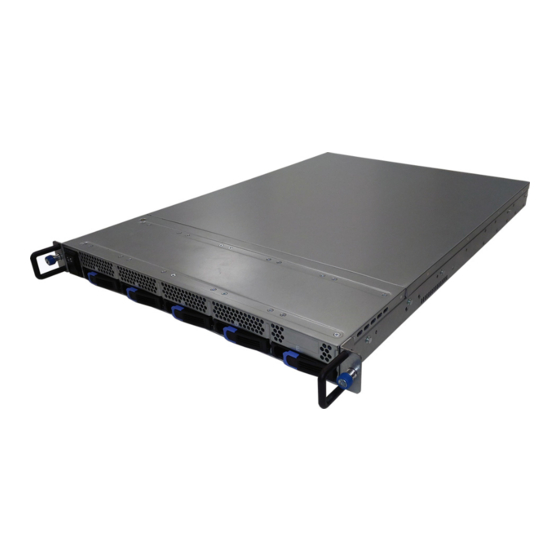
Page 20: About The Product
System Front View M1716G75-FPB I/O and LED Indication Power/ID LED LAN2 LED LAN1 LED Warning (IPMI) LED HDD LED Power Button ID Button (UID) Reset Button NOTE: HDD form factor and capacity size support: 2.5” Enterprise 15mm SATA & SAS SSD/HDD http://www.tyan.com... -
Page 21: Led Definitions
Press once the ID (UID) on the Front Panel, the blue ID LED on the rear panel ID(UID) Button will light up. The Power LED on the front panel will turn blue. Power up and power down the system Power On/Off Button (Use a pin) http://www.tyan.com... -
Page 22: System Rear View
RJ45 LAN Link/Activity LED Scheme Left LED Right LED (Link/Activity) (Speed) No Link Link Green 10 Mbps Active Blinking Green Link Green Solid Green 100 Mbps Active Blinking Green Solid Green Link Green Solid Yellow 1000 Mbps Active Blinking Green Solid Yellow http://www.tyan.com... - Page 23 ID LED will light blue if the system is identified. Users from remote sites can also activate the ID LED by entering a few commands in IPMI. For detailed software support, please visit http://www.tyan.com for the latest AST2500 user guide.
-
Page 24: System Top View
1.5.4 System Top View HDD Bays (M1716G75-FPB pre-installed) System Fans Riser Card Bracket (M2096-6E pre-installed) Power Supply NOTE: The system is pre-installed with S7106 mainboard. http://www.tyan.com... -
Page 25: Board Image
1.5.5 Board Image S7106 This picture is representative of the latest board revision available at the time of publishing. The board you receive may not look exactly like the above picture. http://www.tyan.com... -
Page 26: Block Diagram
1.5.6 Block Diagram S7106 Block Diagram NOTE: Please refer to Tyan S7106 User Guide for more MB details. http://www.tyan.com... -
Page 27: Chapter 2: Setting Up
Caution! To avoid damaging the motherboard and associated components, use torque force within the range kgf/cm (4.35 ~ 6.09 lb/in) on each mounting screw for motherboard installation. Do not apply power to the board if it has been damaged. http://www.tyan.com... -
Page 28: Precautions
Working on a system that is connected to a power supply can be extremely dangerous. Follow the guidelines below to avoid damage to GT62D-B7106 or injury to yourself. Ground yourself properly before removing the top cover of the system. -
Page 29: Installing Motherboard Components
CPUs, memory modules, HDD and PCI-E cards. 2.1.1 Removing the Chassis Cover Follow these instructions to remove the GT62D-B7106 chassis cover. Loosen the thumb screw on the back side. Slide the top cover out. Take off the top cover. http://www.tyan.com... -
Page 30: Replacing The Chassis Cover
2.1.2 Replacing the Chassis Cover Follow these instructions to replace the GT62D-B7106 chassis cover. Place the top cover onto the chassis and slide the top cover into place. Secure the thumb screw. NOTE: The thumbscrew should be tightened with a screwdriver after the top chassis is closed. -
Page 31: Installing The Cpu And Heatsink
A new heatsink comes with pre-applied thermal grease. Once the heatsink has been removed from the processor, you need to clean the processor and heatsink using an alcohol solvent. Then apply new thermal grease before reinstalling the heatsink. Take out the protection cap. http://www.tyan.com... - Page 32 Align the heatsink on the CPU socket by the guide pins and make sure the gold arrow is located in the correct direction. Then place the heatsink onto the top of the CPU socket. http://www.tyan.com...
- Page 33 To secure the heatsink, use a T30 Security Torx to tighten the screws in a sequential order (1 2 3 4). When disassembling the heatsink, loosen the screws in reverse order (4 3 2 1). http://www.tyan.com...
-
Page 34: Installing The Memory
Press the memory slot locking levers in the direction of the arrows as shown in the following illustration. Align the memory module with the slot. When inserted properly, the memory slot locking levers lock automatically onto the indentations at the ends of the module. http://www.tyan.com... - Page 35 S7106 Memory Location http://www.tyan.com...
- Page 36 - Use the same # of ranks per DIMM 4. Dual-rank DIMMs are recommended over single-rank DIMMs. 5. Un-buffered DIMM can offer slightly better performance than registerd DIMM if populating only a single DIMM per channel. 6. Always install with CPU0 Socket and DIMM_0 Slot first. http://www.tyan.com...
- Page 37 - Use the same # of ranks per DIMM 4. Dual-rank DIMMs are recommended over single-rank DIMMs. 5. Un-buffered DIMM can offer slightly better performance than registerd DIMM if populating only a single DIMM per channel. 6. Always install with CPU0 Socket and DIMM_0 Slot first. http://www.tyan.com...
-
Page 38: Installing Hard Drives
2.1.5 Installing Hard Drives The GT62D-B7106 supports (5) 2.5” SSD or HDD. Follow these instructions to install a hard drive. Press the locking lever latch to pull the locking lever open. Slide the HDD tray out. http://www.tyan.com... - Page 39 Remove the 4 screws. Place a hard drive into the drive tray. Use 4 screws to secure the HDD. Reinsert the HDD tray into the chassis and press the locking lever to secure the tray. http://www.tyan.com...
-
Page 40: Rack Mounting
2.2.1 Installing the Server in a Rack NOTE: Before mounting the TYAN GT62D-B7106 in a rack, ensure that all internal components have been installed and that the unit has been fully tested. 2.2.2 Installing the inner Rails to the Chassis Follow these instructions to install the inner rails to the chassis. - Page 41 Install the inner rail to the chassis. Push the inner rail backwards to lock the rail in place. http://www.tyan.com...
-
Page 42: Installing The Outer Rails To The Rack
Installing the Outer Rails to the Rack NOTE: Before mounting the TYAN GT62D-B7106 in a rack, ensure that all internal components have been installed and that the unit has been fully tested. However, to make the installation easier, we suggest that you remove all HDD trays before you insert the chassis to the rack. - Page 43 http://www.tyan.com...
- Page 44 Draw out the outer rails. Align the inner rails with the outer rails. Push the blue locking tab on both sides simultaneously to slide the chassis back into the rack. http://www.tyan.com...
- Page 45 Secure the chassis to the rack using 2 thumb screws. The installation is now complete. http://www.tyan.com...
-
Page 46: Removing The Server From A Rack
2.2.4 Removing the Server from a Rack Follow these instructions to remove the TYAN GT62D-B7106 from an industry standard 19” rack. Unscrew the chassis from the rack. Slide the chassis forwards. Press the locking tab on both sides simultaneously to slide the chassis out from the rack. -
Page 47: Chapter 3: Replacing Pre-Installed Components
Chapter 3: Replacing Pre-Installed Components 3.0.1 Introduction This chapter explains how to replace the pre-installed components, including the S7106 Motherboard, M2096-6E Riser Board, System Fan and Power Supply Unit etc. 3.0.2 Disassembly Flowchart The following flowchart outlines the disassembly procedures. http://www.tyan.com... -
Page 48: Removing The Cover
Removing the Cover Before replacing any parts you must remove the chassis cover. Follow Section 2.1.1 Removing the Chassis Cover to remove the cover of the GT62D-B7106. Replacing the Riser Card Follow these instructions to replace the M2096-6E Riser card. -
Page 49: Riser Card Features
3.2.1 Riser card Features Front View Rear View M2096-6E Riser Card PCB Dimensions: 12.2x2.8cm, thickness 1.6mm Layer: 6 layers 2 OCuLink Connectors, can support up to 4 I/O Port NVME SSDs http://www.tyan.com... -
Page 50: Replacing The System Fans
Replacing the System Fans Follow these instructions to replace the system fans. Disconnect the fan cable of the failed fan from the mainboard. Take out the failed fan. Pull the front rubber screws out. http://www.tyan.com... - Page 51 Pull the rear rubber screws out. After replacing the new fan, follow the steps described earlier in reverse order to reinstall the fan into the chassis. http://www.tyan.com...
-
Page 52: Replacing The Power Supply
Please unplug the power cord before you follow these instructions to replace the power supply units. Unscrew the power supply module. Disconnect the power cable. After replacing a new power supply unit, follow the procedures in reverse order to reinstall the power supply back into the chassis. http://www.tyan.com... -
Page 53: Removing Motherboard Procedures
Removing Motherboard Procedures Follow these instructions to replace the motherboard. 3.5.1 Disconnecting All Motherboard Cables First unscrew the Riser Card Bracket and then disconnect the NVME cable to lift up the Riser Card Bracket. Disconnect all cables connected to the motherboard. http://www.tyan.com... -
Page 54: Removing The Motherboard
After removing all of the aforementioned cables, follow the instructions below to remove the motherboard from the chassis. Remove the air duct, processor and heatsink if installed. Remove nine screws securing the motherboard to the chassis. Carefully lift the motherboard from the chassis. http://www.tyan.com... -
Page 55: Appendix I: Cable Connection Tables
2. 8X Oculink to (2)SFF8639 Cable M2096-4E to NVME Device Cable M2096-6E Connect to NVME 8X Oculink to NVME1/ (2)SFF8639 NVME 45 → NVME2 Cable 3. FP Control Cable Front Panel Board (FPB) to S7106 (MB) M1716G75-FPB Connect to S7106GMR-CGN Control Cable FPIO_1 → http://www.tyan.com... - Page 56 4. Power Cable Power Supply to S7106 (MB) DPS-500AB-22 M Connect to S7106GMR-CGN PWR1 2x12P Cable → 2x4P Cable → 2x4P Cable → 8X OCulink B4P Cable → Cable → PSMI Cable PSMI_HD1 http://www.tyan.com...
-
Page 57: Appendix Ii: Fan And Temp Sensors
This section aims to help readers identify the locations of some specific FAN and Temp Sensors on the motherboard. A table of BIOS Temp sensor name explanation is also included for readers’ reference. NOTE: The red mark indicates the sensor. http://www.tyan.com... - Page 58 Fan and Temp Sensor Location: Fan Sensor: It is located in the third pin of the fan connector, which detects the fan speed (rpm) Temp Sensor: Temp. Temp sensor detects the system temperature around. BIOS Temp Sensor Name Explanation: http://www.tyan.com...
- Page 59 Interface (PECI) PCH_Area_Temp Temperature of the PCH Area SAS_Area_Temp Temperature of the SAS Area (reserved for TYAN OCP SAS Card) LAN_Area_Temp Temperature of the LAN Area (reserved for TYAN OCP LAN Card) SYS_Inlet_Temp Temperature of the Air Inlet Area (reserved for TYAN FPB)
- Page 60 Temperature of CPU1 DIMM D0 Slot CPU1_DIMM_D1 Temperature of CPU1 DIMM D1 Slot SYS_FAN_1 Fan Speed of SYS_FAN_1 SYS_FAN_2 Fan Speed of SYS_FAN_2 SYS_FAN_3 Fan Speed of SYS_FAN_3 SYS_FAN_4 Fan Speed of SYS_FAN_4 SYS_FAN_5 Fan Speed of SYS_FAN_5 SYS_FAN_6 Fan Speed of SYS_FAN_6 http://www.tyan.com...
-
Page 61: Appendix Iii: Fru Parts Table
Appendix III: FRU Parts Table GT62D-B7106 FRU Parts Model Item Part Number Picture Description Number TF-POWER SUPPLY;SBU,500 Power 471100000403 W,DELTA,DPS-500AB-22 M,(S1F),1U Supply MODULE,REV.S1F 336210000047 22000RPM,60.5dBA,60g,40*40*28mm,4PIN 411T59900007 M2096-6E Riser card , R01 PCBA 411T56500159 S7106GMR-CGN/MB,R03 Rack Mounting 452T56500007 Slide Rail Kit Parts OCuLink 8X 80P+B4P(F),P5.08/SFF-8639 68P... - Page 62 NOTE http://www.tyan.com...
-
Page 63: Appendix Iv: Technical Support
MITAC serves multiple market segments with the industry’s most competitive services to support them. Please feel free to contact us directly for this service at tech-support@tyan.com Help Resources: 1. See the beep codes section of this manual. - Page 64 (RMA) number. The RMA number should be prominently displayed on the outside of the shipping carton and the package should be mailed prepaid. TYAN will pay to have the board shipped back to you. TYAN® GT62D-B7106 Service Engineer’s Manual V1.0a Document No.:...
Need help?
Do you have a question about the GT62D-B7106 and is the answer not in the manual?
Questions and answers