Table of Contents
Advertisement
Quick Links
Advertisement
Table of Contents

Related Manuals for Recent RS-918SSB

Summary of Contents for Recent RS-918SSB
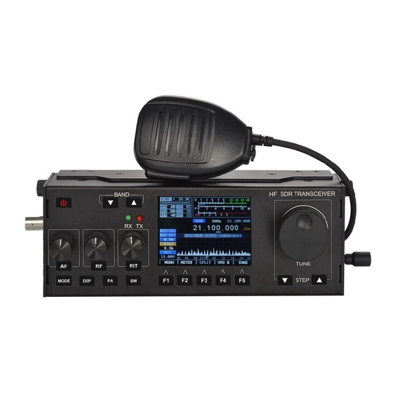
- Page 1 RS-918SSB HF SDR Transceiver FEBRUARY 15, 2018...
-
Page 2: Table Of Contents
Table of Contents mcHF UI Element Naming Convention..................4 mcHF Basic Screen Layout ......................4 LCD Touchscreen Functions ......................5 Key Press Map ........................... 8 UHSDR Quick Operating Guide ....................17 Menu Entries Explained ........................19 How to Operate the Menu ........................19 Menu Overview (Automatically Generated) .................. - Page 3 Frequency Calibration ........................76 TX calibration approach [from firmware 1.5.8] ..............76 RX calibration approach [from firmware 1.5.8] ..............76 CW TUNE HELPER ..........................78 how to use it ............................ 78 How does the frequency snap mode work? ................. 78 Details for programmers ........................
- Page 4 Provided functionalities ........................96 Enabling/Disabling USB CAT/AUDIO..................... 97 Programs known to work ......................... 97 Programs for controlling the rig ....................97 Programs used to receive/transmit digital modes ..............97 Programs used to receive/transmit CW ..................98 SDR Programs for use with IQ Data ................... 98 Installation on Windows XP - 8.1 ....................
-
Page 5: Mchf Ui Element Naming Convention
Operating Manual There is another project which provides operating manual on gitbook started by Marc, EA3HZZ. You can access this project here. Contributors / collaborators are welcome as in github, too :) If not mentioned otherwise, the information below applies to the newest daily build. So sometimes there may be some differences if you use older firmware releases. -
Page 6: Lcd Touchscreen Functions
Filter Box Shows the name of the currently selected RX (!) audio filter. Top line is the upper frequency, lower line the characteristic parameter: BPF -> ~300 - upper frequency • LPF -> 0 - upper frequency • otherwise width (300/500 -> for narrow CW filters) or center frequency (for •... - Page 7 Where Short Press Long Press Comment Works "<" Waterfall/Scope also in big Waterfall/Scop magnification size mode e bar reduced with no bar shown Works ">" Waterfall/Scope also in big Waterfall/Scop magnification size mode e bar increased with no bar shown Toggle Works Left side...
- Page 8 Where Short Press Long Press Comment Short MODE Button Toggle Menu Mode Press Label Button F1 Audio Signal Next audio source Encoder 3 & M3 Short TX Power Box Next TX power level Press Button G3 Use if you have "twin Restart Codec I2S DSP Box peaks...
-
Page 9: Key Press Map
Extra Touch Actions You can get a preview how it looks if mcHF selects new bands provided by future expansion PCBs if you touch "40" of S-Meter (rf-bands-mod) or "60" of S-Meter (vhf/uhf-bands-mod) on touchscreen when you are in hardware-menu (touching toggles pcb present or not "hard-coded"). - Page 10 Name of When Short Press Long Press Comment Key(s) Select Encoder 1 Value long press: toggle Select Encoder No Menu between Noise 2 Value Blanker & AGC mode Select Encoder long press: 2 Value (no toggle Menu change via between Noise Mode Encoder 2 Blanker &...
- Page 11 Name of When Short Press Long Press Comment Key(s) Changes DSP DSP Off Modes Switches Power Levels Switches Enables Filter Predefined Selection by Filters Encoder 3 Encoder 3 Disables Filter Encoder 3 Filter Selection Selection Active Toggles Menu Save Config to Mode EEPROM Change Meter...
- Page 12 Name of When Short Press Long Press Comment Key(s) Next Menu Last Menu Menu Page Page Copy active No Menu Toggle VFO A/B VFO Freq to inactive VFO Reset Menu Menu Item Value to Mode Default Disable/Enable Start/Stop Tune Temporarily Decrease STEP- Enable Smaller...
- Page 13 Name of When Short Press Long Press Comment Key(s) Splash Ask for Reset to F1+F3+F5 screen Default Config Splash Ask for Reset to F2+F4 screen VFOs to default Button and Splash Any Button Touchscreen screen Test Splash Touchscreen Touchscreen screen Calibration Encoder 1 &...
- Page 14 M2 is used to select the following settings/values with a short press. Change these values using Encoder 2. The actively controlled value is typically indicated using a yellow box background. In Menu Mode Encoder 2 is used to select items or sub menus. Use Encoder 3 to change or hide/show sub menus.
- Page 15 Label Name When Comment RX frequency deviation (20Hz steps) Microphone Microphone jack Signal TX Left Line L>L Line IN jack, left channel IN Signal TX Right Line L>R Line IN jack, right channel IN Signal TX USB Audio USB Speaker, 48kHz stereo, but only left Signal channel is used 48Khz IQ Baseband Signal e.g.
- Page 16 A long press toggles to the alternative mode for the currently selected mode (Mode1 -> Mode2 and Mode2 -> Mode1): Mode1 Mode2 Mode3 Mode4 SAM-L SAM-U SAM-L SAM-U CW-L CW-U DI-L DI-U FM-W FM-N Color and Blink Codes of the LEDs Explained Green State Red Led...
- Page 17 Frequency Display Explained The frequency display operates in two modes, normal mode and split mode. Color Codes of the Main Display Digit Meaning Color White Normal operation, device tuned to frequency Outside specifications of the local oscillator chip Si570, but still usable Yellow frequency Non-tunable frequency, transmit disabled, LO operates at last valid...
-
Page 18: Uhsdr Quick Operating Guide
UHSDR Quick Operating Guide This document is useful if you are looking for a very simple guide how to operate the mcHF: The Chinese translate at here Also available as and SVG. The SVG is the source document and is maintained using Inkscape. - Page 19 Each release will contain the matching document in its zip/tar source code archive (from version 1.5.5). See the releases.
-
Page 20: Menu Entries Explained
Menu Overview (Automatically Generated) Since Xmas 2016 there is an automatic generated manual regarding menu items. Because of it may change recently please follow this link: Here you'll find the most recent menu item overview for the last daily build... -
Page 21: Uhsdr Firmware V
uhsdr firmware v.. - UI Menu Overview generated at 2018-02-10T09:41:57 by "./ui_menu_structure_mdtable.py" Standard Menu ( MENU_BASE LABEL (NR) DESCRIPTION If enabled, the appropriate LSB/USB Auto sideband mode for SSB and Select (MENU_SSB_AUTO_MODE_SELECT) FreeDV is chosen as default for each band by its frequency. Disable appearance of digital Digital Modes (MENU_DIGI_DISABLE) modes when pressing Mode... - Page 22 LABEL (NR) DESCRIPTION stability and transient response of the PLL. Larger values give faster lock even if you are off tune, but PLL is also more sensitive. Bandwidth of the PLL loop = OmegaN in Hz: smaller bandwidth = more stable lock. FAST LOCK SAM PLL - set Step SAM PLL bandwidth in response and PLL bandwidth to...
- Page 23 LABEL (NR) DESCRIPTION Enable detection of CTCSS tones FM Sub Tone during FM receive. RX is muted Dot (MENU_FM_DET_SUBAUDIBLE_TONE) unless tone is detected. Enabled sending of short tone at beginning of each FM FM Tone transmission. Used to open Burst (MENU_FM_TONE_BURST_MODE) repeaters.
- Page 24 LABEL (NR) DESCRIPTION band noise for every particular RX situation to allow for optimal AGC action. The blue AGC box indicates when AGC action takes place and helps in adjusting this threshold. Enable/Disable Hang AGC function: If enabled: after the signal has decreased, the gain of AGC WDSP Hang the AGC is held constant for a...
- Page 25 LABEL (NR) DESCRIPTION Sets the Codec IQ signal gain. Higher values represent higher RX Codec Gain (MENU_CODEC_GAIN_MODE) gain. If set to AUTO the mcHF controls the gain so that the best dynamic range is used. Controls offset of the receiver IQ signal base frequency from the dial frequency.
- Page 26 LABEL (NR) DESCRIPTION predefined value of selected compression level. If Audio Compressor Config is set to CUSTOM, sets the value of TX ALC Input the ALC Input Gain. Otherwise Gain (MENU_ALC_POSTFILT_GAIN) shows predefined value of selected compression level. Set the Noise Blanker strength. Higher values mean more RX NB aggressive blanking.
-
Page 27: Configuration Menu (Menu_Conf)
LABEL (NR) DESCRIPTION Backup your I2C Configuration to flash. If you don't have suitable Backup Config ( MENU_BACKUP_CONFIG) I2C EEPROM installed this function is not available. Shutdown automatically when Low Voltage Shutdown ( supply voltage is below MENU_LOW_POWER_SHUTDOWN) threshold for 60 seconds (only in RX). - Page 28 LABEL (NR) DESCRIPTION frequency is out of the official ham bands. DO NOT USE WITH CONNECTED ANTENNA! Use a dummy load! Disable all transmissions unconditionally. In CW you will Transmit Disable (CONFIG_TX_DISABLE) be able to hear a side tone but no transmission is made.
- Page 29 LABEL (NR) DESCRIPTION otherwise. You may switch this signal off here. When switching from RX to TX the audio and HF output will be muted for roughly VALUE ms. There are now several minimum times for muting defined in the firmware: Input from Mic: 40ms...
- Page 30 LABEL (NR) DESCRIPTION potential source of noise if Mic is input! You need to increase the delay or change switches! Set maximum speaker Max Volume (CONFIG_MAX_VOLUME) headphone volume. Set the constant gain level for Lineout Gain (CONFIG_LINEOUT_GAIN) the analog lineout jack If ON each keypress will Key Beep (CONFIG_BEEP_ENABLE)
- Page 31 LABEL (NR) DESCRIPTION selected frequencies. Select which frequency is reported via CAT Interface to the connected PC in Digital IQ Mode. If ON, it reports the CAT-DIQ-FREQ-XLAT (CONFIG_CAT_XLAT) displayed frequency. If OFF, it reports the center frequency, which is more useful with SDR programs.
- Page 32 LABEL (NR) DESCRIPTION the XVERTER Offset to the LO Frequency of it. The mcHF frequency is multiplied by this factor before the offset is added, so anything but 1 will result in each Hz in the mcHF being displayed as 2 to 10 Hz change on display.
- Page 33 LABEL (NR) DESCRIPTION Step+ and vice versa. If ON, Band- behaves like Band+/- Button Swap (CONFIG_BAND_BUTTON_SWAP) Band+ and vice versa. Start using the RTC and use the modified button layout. Will reboot your mcHF. Please use only if you completed the RTC mod otherwise you RTC Start (CONFIG_RTC_START)
- Page 34 LABEL (NR) DESCRIPTION Sets the Real Time Clock RTC Min (CONFIG_RTC_MIN) Minutes. Needs Modifications. Sets the Real Time Clock RTC Seconds (CONFIG_RTC_SEC) Seconds. Needs Modifications. Full Reset of STM32 RTC. Can be used to RTC Reset (CONFIG_RTC_RESET) simulate first start with RTC mod completed Sets the Real Time Clock...
- Page 35 LABEL (NR) DESCRIPTION voltage warning colors and auto shutdown. Adjust the frequency correction of the local oscillator. Measure TX frequency and adjust until both Freq. Calibrate (CONFIG_FREQUENCY_CALIBRATE) match. Or use receive a known reference signal and zero-beat it and then adjust. More information in the Wiki.
- Page 36 LABEL (NR) DESCRIPTION when Disp. Pwr (mW), is enabled. Needs SWR meter hardware modification to work. See Wiki Adjustment and Calibration. Exchange the assignment of the Power/SWR FWD and REV SWR/PWR Meter FWD/REV measurement Swap (CONFIG_FWD_REV_SENSE_SWAP) ADC. Use if your power meter does not show anything during...
- Page 37 LABEL (NR) DESCRIPTION Sets speed of the I2C2 bus (Audio Codec and I2C EEPROM). Higher speeds provide quicker RX/TX switching, configuration save and power I2C2 Bus Speed (CONFIG_I2C2_SPEED) off. Speeds above 200 kHz are not recommended for unmodified mcHF. Many modified mcHF seem to run with 300kHz...
- Page 38 LABEL (NR) DESCRIPTION algorithm achieves up to 60dB mirror rejection. See Wiki Adjustments and Calibration. IQ Balance Adjust for all receive if frequency translation is NOT OFF. RX IQ Balance (80m) (CONFIG_80M_RX_IQ_GAIN_BAL) Requires USB/LSB/CW mode to be changeable. See Wiki Adjustments and Calibration.
- Page 39 LABEL (NR) DESCRIPTION IQ Balance Adjust for all receive if frequency translation is NOT OFF. RX IQ Balance (10m) (CONFIG_10M_RX_IQ_GAIN_BAL) Requires USB/LSB/CW mode to be changeable. See Wiki Adjustments and Calibration. IQ Phase Adjust for all receive if frequency translation is NOT OFF.
- Page 40 LABEL (NR) DESCRIPTION Wiki Adjustments and Calibration. IQ Phase Adjust for all transmission if frequency translation is NOT OFF. TX IQ Phase (80m) (CONFIG_80M_TX_IQ_PHASE_BAL) Requires USB or LSB mode to be changeable. See Wiki Adjustments and Calibration. IQ Phase Adjust for all transmission if frequency...
- Page 41 LABEL (NR) DESCRIPTION Requires USB or LSB mode to be changeable. See Wiki Adjustments and Calibration. IQ Balance Adjust for CW transmissions (and all TX IQ Balance (80m, transmission if CW) (CONFIG_80M_TX_IQ_GAIN_BAL_TRANS_OFF) frequency translation is OFF). See Wiki Adjustments and Calibration. IQ Phase Adjust for CW transmissions...
- Page 42 LABEL (NR) DESCRIPTION OFF). See Wiki Adjustments and Calibration. IQ Phase Adjust for CW transmissions (and all TX IQ Phase (10m, transmission if CW) (CONFIG_10M_TX_IQ_PHASE_BAL_TRANS_OFF) frequency translation is OFF). See Wiki Adjustments and Calibration. DSP LMS noise reduction: length of the audio buffer that is used for simulation of a...
- Page 43 LABEL (NR) DESCRIPTION (and larger FIR filter) uses more MCU resources. DSP LMS noise reduction: Number of taps in the DSP noise reduction FIR filter. The larger the number of DSP NR FIR NumTaps (CONFIG_DSP_NR_FFT_NUMTAPS) taps in the filter, the better the performance, but the slower performance of...
- Page 44 LABEL (NR) DESCRIPTION DSP LMS automatic notch filter: length of the audio buffer that is used for simulation of a reference for the LMS algorithm. The longer the buffer, the DSP Notch better -and the BufLen(CONFIG_DSP_NOTCH_DECORRELATOR_BUFFER_LENGT slower- the performance, but this buffer length must always be larger than the...
- Page 45 LABEL (NR) DESCRIPTION but the slower performance of the filter and the mcHF. DSP LMS DSP Notch automatic notch ConvRate (CONFIG_DSP_NOTCH_CONVERGE_RATE) filter: DSP LMS automatic notch filter: length of the audio buffer that is used for simulation of a reference for the LMS algorithm.
-
Page 46: Display Menu (Menu_Display)
LABEL (NR) DESCRIPTION DSP LMS automatic notch filter: Number of taps in the DSP automatic notch FIR filter. The larger the number of taps DSP Notch FIRNumTap (CONFIG_DSP_NOTCH_FFT_NUMTAPS) in the filter, the better the performance, but the slower performance of the filter and the mcHF. - Page 47 LABEL (NR) DESCRIPTION consumption is decreased and RX hum is decreased, too. LCD operation starts when using any button or the touchscreen. If enabled, you'll see a line Step Size under the digit which is Marker (CONFIG_FREQ_STEP_MARKER_LINE) currently representing the selected tuning step size Filter BW Color of the horizontal Filter...
- Page 48 LABEL (NR) DESCRIPTION to represent data. LIGHT is a little less resource intensive. Lower Values: Higher Scope 1/Speed (MENU_SCOPE_SPEED) refresh rate. Set to 0 to disable scope. Adjusting of scope / Scope AGC Adj. (MENU_SCOPE_AGC_ADJUST) waterfall AGC for fitting graphs to screen Scope Trace Set color of scope Colour (MENU_SCOPE_TRACE_COLOUR)
- Page 49 LABEL (NR) DESCRIPTION Adjust to fit your personal input level range to Wfall Contrast (MENU_WFALL_CONTRAST) displayable color range for waterfall Set the color of the scale of Upper Meter Colour (MENU_METER_COLOUR_UP) combined S/Power-Meter Set the color of the scale of Lower Meter combined SWR/AUD/ALC- Colour (MENU_METER_COLOUR_DOWN)
-
Page 50: Cw Mode Settings (Menu_Cw)
LABEL (NR) DESCRIPTION Inverts Enc2/Enc3 behavior in menu up/down and Menu Inverse show/hide UI scrolling Scrolling (MENU_UI_INVERSE_SCROLLING) actions, used for side- mounted encoder dials. CW Mode Settings ( MENU_CW LABEL (NR) DESCRIPTION Select how the mcHF interprets the connected keyer signals. Supported CW Keyer Mode (MENU_KEYER_MODE) modes: Iambic A and B Keyer (IAM A/B), Straight Key... - Page 51 LABEL (NR) DESCRIPTION Sidetone Frequency (also CW Side/Offset Offset frequency, see CW Freq (MENU_SIDETONE_FREQUENCY) Freq. Offset below) Dit is Dah and Dah is Dit. Use CW Paddle Reverse (MENU_PADDLE_REVERSE) if your keyer needs reverse meaning of the paddles. How long to stay in CW TX CW TX->RX Delay (MENU_CW_TX_RX_DELAY) mode after stop sending a signal.
-
Page 52: Filter Selection (Menu_Filter)
LABEL (NR) DESCRIPTION graphical tune helper: adjust frequency until yellow vertical Tune line is in center of green box - helper (MENU_CW_DECODER_SNAP_ENABLE) -> right on CW carrier frequency How many samples are taken Blocksize for for the signal detection with Goertzel (MENU_CW_DECODER_BLOCKSIZE) the Goertzel algorithm? Noise... - Page 53 LABEL (NR) DESCRIPTION Filter bandwidth #3 when toggling with SSB Filter 3 (MENU_FP_SSB_03) filter select button in LSB or USB. Filter bandwidth #4 when toggling with SSB Filter 4 (MENU_FP_SSB_04) filter select button in LSB or USB. Filter bandwidth #1 when toggling with CW Filter 1 (MENU_FP_CW_01) filter select button in CW.
-
Page 54: Pa Configuration (Menu_Pow)
LABEL (NR) DESCRIPTION Select if SSB-TX signal is filtered SSB TX Audio (strongly recommended to agree to Filter2 (CONFIG_SSB_TX_FILTER) regulations) PA Configuration ( MENU_POW LABEL (NR) DESCRIPTION Select the power level for TUNE operation. May be Tune Power Level (CONFIG_TUNE_POWER_LEVEL) set using the selected power level or have a fixed power level. - Page 55 LABEL (NR) DESCRIPTION If set frequencies above 8Mhz (30m or higher) require higher power adjust Reduce Power on High values (four times). This Bands (CONFIG_REDUCE_POWER_ON_HIGH_BANDS) permits better control of generated power on these frequencies. Defines the BIAS value of the PA. See Adjustment and PA Bias (CONFIG_PA_BIAS) Calibration for more information.
- Page 56 LABEL (NR) DESCRIPTION Defines the internal power adjustment factor to achieve 5W power on this 80m 5W PWR Adjust (CONFIG_80M_5W_ADJUST) band. See Adjustment and Calibration for more information. Defines the internal power adjustment factor to achieve 5W power on this 60m 5W PWR Adjust (CONFIG_60M_5W_ADJUST) band.
- Page 57 LABEL (NR) DESCRIPTION Defines the internal power adjustment factor to achieve 5W power on this 17m 5W PWR Adjust (CONFIG_17M_5W_ADJUST) band. See Adjustment and Calibration for more information. Defines the internal power adjustment factor to achieve 5W power on this 15m 5W PWR Adjust (CONFIG_15M_5W_ADJUST) band.
- Page 58 LABEL (NR) DESCRIPTION Defines the internal power adjustment factor to achieve 5W power on this 4m 5W PWR Adjust (CONFIG_4M_5W_ADJUST) band. See Adjustment and Calibration for more information. Defines the internal power adjustment factor to achieve 5W power on this 2m 5W PWR Adjust (CONFIG_2M_5W_ADJUST) band.
- Page 59 LABEL (NR) DESCRIPTION and Calibration for more information. Defines the internal power adjustment factor to achieve full power on this 630m Full PWR band. Check the output Adjust (CONFIG_630M_FULL_POWER_ADJUST) signal when adjusting for full power! See Adjustment and Calibration for more information.
- Page 60 LABEL (NR) DESCRIPTION and Calibration for more information. Defines the internal power adjustment factor to achieve full power on this 40m Full PWR band. Check the output Adjust (CONFIG_40M_FULL_POWER_ADJUST) signal when adjusting for full power! See Adjustment and Calibration for more information.
- Page 61 LABEL (NR) DESCRIPTION and Calibration for more information. Defines the internal power adjustment factor to achieve full power on this 15m Full PWR band. Check the output Adjust (CONFIG_15M_FULL_POWER_ADJUST) signal when adjusting for full power! See Adjustment and Calibration for more information.
- Page 62 LABEL (NR) DESCRIPTION and Calibration for more information. Defines the internal power adjustment factor to achieve full power on this 4m Full PWR band. Check the output Adjust (CONFIG_4M_FULL_POWER_ADJUST) signal when adjusting for full power! See Adjustment and Calibration for more information.
- Page 63 LABEL (NR) DESCRIPTION and Calibration for more information. Power Meter Adjustment 2200m Coupling factor for the 2200m band Adj. (CONFIG_FWD_REV_COUPLING_2200M_ADJ) power values. See Wiki. Power Adjustment factor 630m Coupling for the 630m band power Adj. (CONFIG_FWD_REV_COUPLING_630M_ADJ) values. See Wiki. Power Meter Adjustment 160m Coupling factor for the 160m band Adj.
-
Page 64: System Info (Menu_Sysinfo)
LABEL (NR) DESCRIPTION Power Meter Adjustment 6m Coupling factor for the 6m band Adj. (CONFIG_FWD_REV_COUPLING_6M_ADJ) power values. See Wiki. Power Meter Adjustment 2m Coupling factor for the 2m band Adj. (CONFIG_FWD_REV_COUPLING_2M_ADJ) power values. See Wiki. Power Meter Adjustment 70cm Coupling factor for the 70cm band Adj. - Page 65 LABEL (NR) DESCRIPTION CPU (INFO_CPU) identification of fitted MCU Flash Size (kB) (INFO_FLASH) flash size of MCU RAM Size (kB) (INFO_RAM) RAM size of MCU Firmware (INFO_FW_VERSION) firmware version Build (INFO_BUILD) firmware: timestamp of building Bootloader (INFO_BL_VERSION) bootloader version RF Bands Mod (INFO_RFMOD) RF bands expansion PCB present? V/UHF VHF/UHF bands expansion PCB present?
-
Page 66: Debug/Exper. Settings (Menu_Debug)
Debug/Exper. Settings ( MENU_DEBUG LABEL (NR) DESCRIPTION Enable debug outputs on LCD for testing purposes (touch screen Enable Debug Info coordinates, load) and Display (MENU_DEBUG_ENABLE_INFO) audio interrupt duration indication via green led Enable automatic sidetone correction for CW OFFSET MODE = SHIFT. - Page 67 LABEL (NR) DESCRIPTION time constant beta for NR beta (MENU_DEBUG_NR_BETA) spectral noise reduction, leave at 0.85 NR asnr (MENU_DEBUG_NR_ASNR) Devel 2 NR: asnr Devel 2 NR: width of NR smooth gain smoothing wd. (MENU_DEBUG_NR_GAIN_SMOOTH_WIDTH) window NR smooth Devel 2 NR: threshold thr.
-
Page 68: Essential Calibration And Setup Steps
Essential Calibration and Setup Steps Once you finished the assembly and loading the firmware, you should run through a number of important setup steps and calibrations. There are plenty more things to configure, but the ones listed here should be done initially. And in most cases, you will not have to touch these again unless you modify the hardware or the firmware improves and you are asked to re-calibrate. -
Page 69: Pa Power Calibration
meter in software. Go to the "Configuration" menu and set "SWR/PWR Meter FWD/REV Swap" to "ON". PA Power Calibration What you will need: 1. Operational PTT switch connected to the microphone/ptt connector or CW paddles connected to the CW keyer port 2. -
Page 70: Tx: Rf Power Adjustment
10. The measured current at this point is the "start mark", write it down. Be sure to have the PA Bias set to the lowest possible value. 11. Now adjust bias so that measure current is 500mA higher than this "start mark". E.g. - Page 71 2. Set "PA Configuration Menu", "Tune Tone" to "Single". 3. Set "PA Configuration Menu", "Tune Power Level" to either "5W" or to "as TX PWR" and change TX power to "5W" 4. Enter "PA Configuration Menu", "xxm 5W PWR Adjust" (replace xx with your bands 10, 12, ...
-
Page 72: Tx: Fm And Digital Modes
TX: Adjustment RF Power Meter The RF Power Meter should be calibrated to show proper values. Calibration needs to be done for some but not all bands, the software calculates the values for other bands. 1. Choose mode LSB or USB. 2. - Page 73 You will need a SSB receiver for 80m and 10m, or a spectrum analyzer for this frequency range. The instructions are given for a frequency translation of -12khz. If you want to use a different translation frequency, it is recommended to run the procedure in the desired translation mode.
-
Page 74: Rx Iq Adjustments [Valid From 1.5.2]
You simply repeat all steps for the 80m band. Only this time in the 10m band and using the TX IQ Balance/Phase 10m settings. The initial USB frequency should be 28.124.000 Mhz (Receive for monitoring original TX signal is LSB: 28.125.500, USB: 28.124.000). The second receiver's LSB (!!) frequency for calibration purposes is 28.100.000 khz. -
Page 75: Swr/Power Meter Calibration
2. Connect signal generator to mcHF (maybe via attenuator regarding output of signal generator) or make sure you can receive your transmitter with sufficient but not too high signal level. 3. The mcHF is used to receive the original signal in USB mode, the secondary signal in LSB mode ! 4. -
Page 76: Calibrate Zero Power Offset
In order to have the SWR/Power meter to be more accurate, you may want to run the calibrations below. Default values are often good enough to start with but the mcHF can be fairly accurate if calibrated properly. Calibrate Zero Power Offset Preparation: You have to make the resistor-change modification to the SWR hardware circuitry. -
Page 77: Frequency Calibration
Frequency Calibration The Si570 is fairly well calibrated, yet even 10ppm accuracy mean 100 Hz @ 10Mhz and almost 300Hz at 28Mhz. The mcHF firmware permits to fine tune the calibration. Equipment needed: Either an as exact and as high as possible reference frequency signal (single •... - Page 78 3. Wait until the SAM demodulator has captured the carrier and the carrier frequency is displayed in the small frequency display and the small frequency display is stable 4. Go into Configuration menu to "Frequency Calib." Adjust the PPM value until the small frequency display shows exactly xxxxxx.000 Hz 5.
-
Page 79: Cw Tune Helper
Automatic Carrier Frequency Tuning CW TUNE HELPER & SNAP MODE CW TUNE HELPER This works as a graphical helper to match your CW RX frequency to the frequency of your QSO partner. It matches your CW offset to your sidetone frequency and graphically shows you the difference between the two. - Page 80 there and does not consume additional computing resources). The values of the complex FFT are magnitude values of signal strength for 256bins across the whole spectrum of 48000Hz. That means, one calculated value for one bin holds the average magnitude for a bin bandwidth (binBW) of 187.5Hz = 48000Hz / 256. A bin bandwidth of 187.5Hz is of course not accurate enough for precision tuning, as necessary for DSB or StereoAM listening.
-
Page 81: Details For Programmers
• take the bins from the display FFT and search in the bins that are in the filter passband (which is usually quite narrow in CW) for the loudest signal (do averaging over several FFT loops). Note the number of that bin •... - Page 82 calculate LBin and Ubin from magnify mode & frequency conversion & • filterpassband rearrange data in sd.FFT_Samples (the buffer with the lowpass-filtered, scaled • complex magnitudes from the FFT) jump into UiSpectrum_CalculateSnap (Lbin, Ubin, posbin, bin_BW) • search for max magnitude value inside the passband (between Lbin and Ubin) •...
-
Page 83: Wdsp Agc
Automatic Gain Control (AGC) WDSP AGC We use this AGC by Warren Pratt which is part of the WDSP library. It was implemented for the UHSDR because it has some more features that might potentially be useful in very specific RX situations. QUICK USER GUIDE FOR THE AGC: 1. -
Page 84: Agc Wdsp Switch
Figure 1: Relationship between input and output signal level WITH (A-->D-->F) and WITHOUT (A-->B-->C) an automatic gain control (AGC) with an indication of some of the WDSP AGC parameters that can be controlled by the user. Inspired by a paper by Phil Harman: “A discussion on the AGC requirements of the SDR1000”... -
Page 85: Agc Wdsp Mode
AGC WDSP Mode choose between predefined parameter sets for the AGC. AGC DECAY is the time needed until the AGC recovers from a strong signal to achieve higher gain for a low signal. AGC threshold this is the most important WDSP AGC parameter. It determines the input signal level where the AGC knee is situated (see figure 1). -
Page 86: Agc Hang Enable
good sounding effect can be adjusted with settings between 3 and 10dB, but that is very dependent on the hearing habits and the personal preference of the user. Experiment with this, until you achieve a pleasant and non-tiring result. AGC Hang enable Enable the Hang AGC which works like this: Hang is enabled when the signal level exceeds the AGC hang time threshold. -
Page 87: Agc Attack
if the AGC WDSP Mode is “OFF”, the user-adjusted figure for “AGC threshold” is taken as the “Fixed gain” in dB. Be very careful, with large signals without AGC, it can be very very loud! AGC Attack This cannot be adjusted by the user and is a constant of 1 millisecond. This is desirable, because when a large signal appears, it is nice to have the AGC react very fast (1ms) in reducing the gain in order to save your ears from damage. -
Page 88: Freedv (Rx & Tx)
Digimodes The UHSDR software supports three digimodes (FreeDV, RTTY, and CW) at the moment. Work is underway to implement some more modes. Common for all digital modes (except for CW decoding, see below): Once only: enable "Digital Modes" in Standard Menu •... -
Page 89: Rtty (Rx & Tx)
decisions for implementation of FreeDV into the UHSDR software. More details here: http://freedv.org/tiki-index.php?page=FreeDV+Specification RTTY (RX & TX) How to operate select digital mode "RTTY" as described above • set AGC speed to very long (very slow) or (best) switch it off completely •... -
Page 90: Rtty Tx (Experimental)
50 bauds • signals at 915 and 1365 Hz • try 4581.865 kHz, 7644.860 kHz, 10099.660 kHz, 11037.860 kHz or 14466.160 kHz • RTTY TX (Experimental) Using CW Keyer Input Switch CW Keyer Mode (CW menu) to Iambic or Ultimate •... -
Page 91: Cw Decoder
Details of the RTTY demodulation chain: filter the incoming audio baseband signal with two 2nd order IIR bandpass filters. • The bandpass frequency for mark and space are adjusted according to the shift used for the specified RTTY mode the result is two narrowband signals which are now separately multiplied to •... -
Page 92: Adjustments
et al. 2016 and the "Machine Learning Challenge" in 2014: http://ag1le.blogspot.de/2014/09/morse-learning-machine-challenge.html). So, for the moment, there seems to be no better CW decoder available than your ears and brain working together (which is somehow appeasing and alarming at the same time ;-)). -
Page 93: Theory
Spike cancel OFF/SPIKE/SHORT yet another spike cancelling algorithm, which helps the decoder to ignore short • noise impulses. Has three options: OFF/SPIKE cancelling/SHORT spikes cancelling Use 3 Goertzels may come in the future, there is nothing to choose here yet •... -
Page 94: Psk
the characters and the inter-character-spaces are then sent to the printer routine • which prints them out on the display One very important addition is an error correction routine which -in the case of a • sequence of dits and dahs that can not be assigned to a character in the look-up- table- tries out several possibilities to eliminate single dots in order to finally match the dit/dah sequence to existing characters in the look out table. -
Page 95: Keyer Functionality
macro as described below, switch back to PSK mode and use TXRX to transmit. Long press TXRX switches from/to buffered/unbuffered mode. In buffered mode it returns to rx after finishing the message unless you keep typing. In unbuffered switch to rx manually. - Page 96 how FlDigi does it HERE why you need a slow or no AGC for RTTY decoding HERE Fldigi source code: CW and RTTY decoding HERE FREEDV http://freedv.org/tiki-index.php Machine recognition of hand sent Morse code incl. C source, by Loftur, GNU GPL3 HERE GUENTHER, J.A.
-
Page 97: Provided Functionalities
USB CAT and AUDIO Mode The provided USB CAT functions (Computer Aided Tuning) in combination with the integrated USB Audio Interface enable you to: Use standard HAM software to control many aspects of the receiver (tuning, • modes, PTT). This is enabled by an emulated serial COM port using the well- documented protocol of Yaseu FT-817 receivers. -
Page 98: Enabling/Disabling Usb Cat/Audio
Enabling/Disabling USB CAT/AUDIO. USB CAT and USB AUDIO is always enabled in current firmware (2.0.0 or newer). You just need to connect PC and mcHF. Connect your PC to the mini-USB port. • Linux machines will now automatically detect both the virtual com port as •... -
Page 99: Programs Used To Receive/Transmit Cw
• Programs used to receive/transmit CW Recent firmware got a special support for PC based CW operation if CW mode is selected on mcHF. Use FT-817 CAT for reading and setting frequencies, in CW modes you may also use the DTR signal of the CAT serial port (same port!) to send CW from the PC via mcHF (PTT has to be handled via CAT protocol). -
Page 100: Installation On Windows Xp - 8.1
You can configure the mcHF to stream IQ data to the PC instead of processed audio (default) using the DIG IQ setting in menu 060 TX AUDIO Source. This will also automatically switch the stream from PC to mcHF to use I/Q Data. Technical parameters of the delivered/accepted IQ stream is 48khz sample rate, left channel I, right channel Q. -
Page 101: I Can See The Speaker/Microphone Device But No Sound Is Coming From/Going To The Mchf. I Have Used An Experimental Firmware With Usb Audio Before
I can see the Speaker/Microphone device but no sound is coming from/going to the mcHF. I have used an experimental firmware with USB Audio before. This might be caused by the sample rate change. You have to tell Windows to switch to the right sample rate (16bit stereo, 48000 Hz). -
Page 102: When I Use Cw-L And Cat, Every Frequency Change Via Cat Switches To Cw-U. Why
Audio Tx is named plughw: card=interface DEV=0 Audio RX is named plughw: card=interface DEV=1 When I use CW-L and CAT, every frequency change via CAT switches to CW-U. Why? That is a consequence of the used FT817 CAT protocol emulation. The FT817 CAT protocol know two CW modes, CW and CW-R. - Page 103 Hip-hop Tips and Tricks Snap to a Frequency Step Grid: When using SNAP to a frequency you can end up on a decimated frequency. You can return to a current frequency step grid by quick turning the frequency knob (dynamic tuning enabled).
-
Page 104: Product Description
Product Description: - HF QRP Transceiver, attach battery 12v and ANT and QSO. - DC IN: 9-13V Max:3A - Output POWER:10W (44dbm) MAX:15W - Transmit: 160, 80, 60, 40, 30, 20, 17, 15, 12 and 10-meter amateur bands. - Receive: 3.5-30 MHz nominal including general coverage, 0.8-32 MHz at reduced specifications. - MODE: CW, LSB, USB, AM, FM (N, W), SAM, FreeDV - Bandwidth:300Hz-10Khz Adj - SWR: Display 1:1 to 5:1 calibrated... - Page 105 There are several options for color "palettes" that range from simple grayscale to "cold-hot" to "rainbow" to represent weak to strong signals.
- Page 106 Frequency stability: +/- 30 Hz at 14 MHz over the range of 10 to 35 C, ambient with the transceiver in the case or better with the TCXO active. (It can be much better than this.) Available TX/RX modes: CW, USB, LSB, AM (full-carrier, double-sideband), SAM (double side band reception) and FM.
- Page 107 DSP Filtering Capability: Noise reduction and Automatic Notch Filter with adjustable parameters. Notch filtering is disabled in CW mode for (obvious reasons!) or when using a "wide" receive bandwidth. (Devel-branch: Because NR activation leads to instability of mcHF it is disabled by default. If you want to use it (and risk instabilities in various scenarios) you can activate NR in config menu "last item."...
- Page 108 1.Receive: Unmodified, approx. 410 mA on 40 meters and below at 13.0 volts, approx. 440 mA on 10 meters, minimum volume, maximum display brightness. The selection of minimum display brightness can reduce this by 40-60mA. The modification to the PA drivers to switch off bias when not in TX mode can reduce this by a further 30-60 mA.
Need help?
Do you have a question about the RS-918SSB and is the answer not in the manual?
Questions and answers