Table of Contents
Advertisement
Quick Links
Advertisement
Table of Contents

Summary of Contents for HD Electric Company NoMAX 900 Series
- Page 1 Gridco, Inc. v. Varentec, Inc. IPR2017-01135 GRIDCO 1008 - 1/22...
- Page 2 Gridco, Inc. v. Varentec, Inc. IPR2017-01135 GRIDCO 1008 - 2/22...
- Page 3 ® HD ELECTRIC COMPANY 1 4 7 5 L A K E S I D E D R I V E • WA U K E G A N , I L L I N O I S 6 0 0 8 5 U . S . A .
- Page 4 Gridco, Inc. v. Varentec, Inc. IPR2017-01135 GRIDCO 1008 - 4/22...
-
Page 5: Table Of Contents
TABLE of CONTENTS Overview ......4 Ordering Information ... . . 5-6 Installation . -
Page 6: Overview
OVERVIEW The NoMax 900 Series switched bank capacitor controls utilize user selectable ® functions and parameters to control switched capacitor banks in the following operating modes: Control Mode NoMax 900T NoMax NoMax ® ® ® Voltage Time Time/Volt Temp Temp/Volt Time/Temp Voltage –... -
Page 7: Ordering Information
ORDERING INFORMATION This catalog number matrix provides the necessary information to create the appropriate desired capacitor control product: NMC 900T 1 4RNN ex mple: SERIES 900T Time functions only Time with voltage override functions Time with temperature and voltage override function VOLTAGE OPTION 120V, 60Hz 240V, 60Hz... -
Page 8: Installation
Line Neutral Open Close Figure 1 – Wiring diagram for a standard 4-stab, 4-lead meter socket INSTALLATION The NoMax 900 Series Controls can be supplied ready for 4 jaw meter ® socket mounting or direct pole mounting. Installing into a Meter Socket – Socket mounted controls are supplied ready for either ringed or ringless meter sockets. -
Page 9: Control Set Up
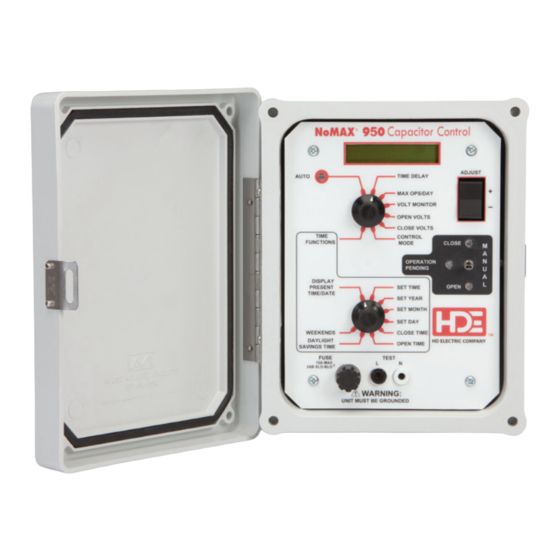
CONTROL SET UP The following section describes the switch positions used to set up the NoMax ® 900 Series Controls. Please refer to Figures 2, 3 & 4. NoMax 900T, 950 NoMAX 900T Unit Figure 2 – ® and 900 Functions 1) Auto This places the control in automatic operation... - Page 10 4) Time Functions – When the upper rotary switch is placed in this position the lower rotary switch becomes active. 5) Display Present Time/Date – The present time and date of the control clock will be displayed. 6) Set Time – Adjusts the time of the control clock. The time is incremented in 5- minute intervals and the rate of change will increase if the adjust switch is held for several seconds.
- Page 11 NoMax 900 Functions 18) OPEN TEMP - The temperature setting threshold for opening the capacitor bank. The minimum value is 5 degrees. The maximum value is 125 degrees (The NoMAX 900 prevents the OPEN TEMP setting from being closer than 5 ®...
-
Page 12: Display Messages
DISPLAY MESSAGES The following describes the messages the user can expect to see on the Liquid Crystal Display. • “Total Ops xxxxxx” The total number of Close operations since installation • “24Hr Auto Ops xx” The number of Automatic Close operations today •... -
Page 13: Fusing
DISPLAY MESSAGES continued • “Wkend = xxxxxxxx” Weekend Enabled/Disabled • “Volt Sensor Err.” The control has determined the Voltage Sensor has failed (NoMax ® 900 and 950) • “Temp. Sensor Err.” The control has determined the Temperature Sensor has failed (NoMax 900 only) ®... -
Page 14: Operation
OPERATION The following settings and features are common to all control modes: Time Delay – Sets the operation time delay period. Using the Adjust switch, select the desired time delay, in seconds, from 3 to 600. This will delay both Open and Close operations in both Manual and Automatic operation mode by the time selected. -
Page 15: Led Indicators
LED INDICATORS Auto – Indicates the Control is in Automatic mode and is using the operator settings to control the Capacitor Bank state. Operation Pending – Flashes to warn the operator an operation is about to occur. In Automatic mode, the LCD displays the type of operation about to occur (i.e. Close or Open), and the amount of time before it occurs. -
Page 16: Automatic Operations
WARNING: The Control will revert to Automatic operation after 10 minutes following a Manual Maintenance Operation. The control will then automatically Open or Close the capacitor bank based upon the Automatic Operation programmed settings. AUTOMATIC ® Figure 5 – NoMAX 900 Unit heck your control for specific functions OPERATIONS... - Page 17 Volts. Similarly, if the next open operation would cause the control voltage to be below the close voltage set point, the operation is not performed until the voltage rises above the close voltage set point plus Delta Volts. Upon power on, Delta Volts is preset to 0.5 volts.
- Page 18 While in Automatic Voltage Control Mode, the control will cycle through several different status messages. The messages include the Total Operations counter, the number of 24 hour Auto operations, the Line Voltage, the Present Time and either the Delta Volts or any activated timer (i.e. the “Close Inhibit” timer, or the Manual Open/Close maintenance timer).
- Page 19 Automatic Temperature Operation – Automatic Temperature Control Mode is active for the NoMAX 900 ® when the Control Mode is set to “Temp. Only” and the rotary switch position is set to AUTO. The AUTO LED will also light. When Automatic Temperature Control Mode is active, the control tests the ambient temperature against the programmed OPEN TEMP and CLOSE TEMP settings.
-
Page 20: Specifications
Automatic Temperature With Voltage Override Operation Automatic Temperature with Voltage Override Control Mode is active for the NoMax ® 900 when the Control Mode is set to “Temp/Volt” and the rotary switch position is set to AUTO. The AUTO LED will also light. When this mode is active, the control will operate as described for Automatic Temperature Operation as long as the sensed voltage is in the “non-Voltage Control Range”... -
Page 21: Limitation Of Warranty & Liability
PRODUCT, OR AT THE ELECTION OF HD ELECTRIC COMPANY OR SELLER, THE REPLACEMENT OF THE PRODUCT. HD Electric Company must have prompt notice of any claim for damage or injury so that an immediate product inspection and investigation of the incident can be made. - Page 22 HD Electric Company is committed to ongoing review and improvement of its product lines, and thus reserves the right to modify product design and specifications without notice. HD Electric Company products are available through HD sales representatives worldwide. Printed in U.S.A.
Need help?
Do you have a question about the NoMAX 900 Series and is the answer not in the manual?
Questions and answers