
Related Manuals for ITech IT-M3800 Series

Summary of Contents for ITech IT-M3800 Series
- Page 1 Regenerative DC Electronic Load IT-M3800 Series User Manual Model: IT-M3800 Series Version: V1.0/01,2022...
- Page 2 CAUTION sign until the in- pose. ITECH shall not be held liable Manual Part Number dicated conditions are for errors or for incidental or indirect fully understood and met.
-
Page 3: Warranty
Warranty ITECH warrants that the product will be free from defects in material and work- manship under normal use for a period of one (1) year from the date of delivery (except those described in the Limitation of Warranty below). -
Page 4: Safety Symbols
Failure to comply with these precautions or specific warn- ings elsewhere in this manual will constitute a default under safety standards of design, manufacture and intended use of the instrument. ITECH assumes no li- ability for the customer’s failure to comply with these precautions. - Page 5 This instrument is used for industrial purposes, do not apply this product to IT power supply system. • Never use the instrument with a life-support system or any other equipment subject to safety requirements. Copyright © Itech Electronic Co., Ltd.
-
Page 6: Environmental Conditions
Make sure the vent hole is always unblocked. Environmental Conditions The instrument is designed for indoor use and an area with low condensation. The table below shows the general environmental requirements for the instrument. Copyright © Itech Electronic Co., Ltd. -
Page 7: Regulation Tag
The service life of the product is 10 years. The product can be used safely within the environmental protection period; oth- erwise, the product should be put into the recycling system. Copyright © Itech Electronic Co., Ltd. -
Page 8: Waste Electrical And Electronic Equipment (Weee) Directive
According to the equipment classifi- cation in Annex I of the WEEE direc- tive, this instrument belongs to the “Monitoring” product. If you want to return the unnecessary instrument, please contact the near- est sales office of ITECH. Copyright © Itech Electronic Co., Ltd. -
Page 9: Compliance Information
2. Connection of the instrument to a test object may produce radiations beyond the specified limit. 3. Use high-performance shielded interface cable to ensure conformity with the EMC standards listed above. Safety Standard IEC 61010-1:2010+A1:2016 Copyright © Itech Electronic Co., Ltd. -
Page 10: Table Of Contents
4.3 Protection Function ....................59 4.3.1 Set Over-Current Protection (OCP)............. 61 4.3.2 Set Over-Power Protection (OPP)............... 62 4.3.3 Set Under-Voltage Protection (UVP)............63 4.3.4 Over-Temperature Protection (OTP)............63 4.3.5 Sense Reverse Protection................64 Copyright © Itech Electronic Co., Ltd. VIII... - Page 11 7 Routine Maintenance ..................... 130 7.1 Instrument Self-Test..................... 130 7.2 Cleaning and Maintenance .................. 130 7.3 Contact of ITECH Engineers ................131 7.4 Return for Repair....................132 A Appendix ........................134 A.1 Specifications of Red and Black Test Cables ............. 134 A.2 Fuse Replacement ....................
-
Page 12: Quick Reference
IT-M3800 series regenerative DC electronic load can not only perform as a DC load, but also feed back power to the grid, which saves electricity and cooling costs for you. - Page 13 Current Power Height Level IT-M3801-10-120 120A 1.2KW IT-M3802-10-240 240A 2.4KW IT-M3803-10-360 360A 3.6KW IT-M3807-10-720 720A 7.2KW IT-M3802-32-80 IT-M3804-32-160 160A IT-M3806-32-240 240A IT-M3812-32-480 480A 12KW IT-M3802-80-40 IT-M3804-80-80 IT-M3806-80-120 120A IT-M3812-80-240 240A 12KW IT-M3802-300-20 300V IT-M3804-300-40 Copyright © Itech Electronic Co., Ltd.
-
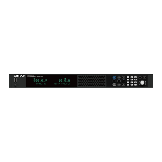
Page 14: Front-Panel Overview
1 Power On/Off switch 5 Numeric and composite keys 2 USB storage device connec- 6 Push-on knob tion port 7 Left, and right cursor navigation keys 3 Vacuum fluorescent display (VFD) 4 Function and composite keys Copyright © Itech Electronic Co., Ltd. -
Page 15: Keyboard Introduction
Enter key 3 Vacuum fluorescent display 7 Push-on knob (VFD) 4 Function and composite keys 1.3 Keyboard Introduction The keyboard introduction of this series instrument is shown as follows. 1U Model 2U Model Copyright © Itech Electronic Co., Ltd. - Page 16 The [Shift]+[XXX](YYY) combination key form identified in this document re- fers to pressing [Shift] button first, then press the [XXX] button, please pay attention to the sequence. Keys Description [Shift]+[Protect] Short circuit function key (Short) [Shift]+[On/Off] Generate a local trigger signal. (Trigger) Copyright © Itech Electronic Co., Ltd.
-
Page 17: Push-On Knob
Confirm the set value or the selected menu item Adjust the Value Setting In the value setting interface, rotate the knob clockwise to increase the set value and anticlockwise to decrease the set value. Copyright © Itech Electronic Co., Ltd. -
Page 18: Rear Panel Introduction
3. Interface for optional accessories IT-E176 and IT-E177 (For details, see Options Introduction) 4. Digital I/O interface: P-IO 5. LAN communication interface 6. CAN communication interface 7. USB communication interface 8. Communication interface of outer ring optical fiber (TX and RX) Copyright © Itech Electronic Co., Ltd. -
Page 19: Vfd Indicator Lamps Description
Indicates that the Trig The instrument is in a state internal status re- of waiting for a trigger. quest event occurs. The load is in a con- stant power input state. Copyright © Itech Electronic Co., Ltd. -
Page 20: Configuration Menu Function
AUTO mode Speed= High/ Loop speed setting: high speed / low speed. On Delay Set the delay time to turn on the input. Off Delay Set the delay time to turn off the input. Copyright © Itech Electronic Co., Ltd. -
Page 21: System Menu Function
2. Press [Enter] on a menu interface to enter the setting interface. 3. After the menu items are set, press [Enter] again to save the modified contents. You can press [Esc] to return to the previous menu. Copyright © Itech Electronic Co., Ltd. - Page 22 Set the communication information between instrument and PC. USB communication interface USB-TMC protocol Virtual serial port Display as the following format: baud rate_data bit_parity bit_stop bit. • Baud rate: 9600 • Data bit: 8 Copyright © Itech Electronic Co., Ltd.
- Page 23 DNS server. If it is not involved, there is no need to set it. • DNS2: 0.0.0.0 Set the DNS server alter- nate address. If it is not in- volved, there is no need to set it. Copyright © Itech Electronic Co., Ltd.
- Page 24 CAN communication interface. Select the baud rate from the following op- Baudrate tions: 5k/10k/20k/40k/50k/80k/100k/125k/ 200k/250k/400k/500k/600k/800k/1000k. Set the instrument address to a number Address from 0 to 127. • Protocol Canfestival: Use standard can protocol. Copyright © Itech Electronic Co., Ltd.
- Page 25 External Analog Function. This function is optional. The menu can only Ext-Program display when corresponding board card is inserted. For details, see 5.12 Analogue Function (Ext-Program) (Optional). System Reset Select whether to restore the factory default settings or not. Copyright © Itech Electronic Co., Ltd.
-
Page 26: Options Introduction
2.5.4 GPIB Interface (Optional). – IT-E177: Interface card that includes RS-232 communication interface, external analog and other functions. The accessory has a total of 10 pins, and the details of each pin are as follows: Copyright © Itech Electronic Co., Ltd. - Page 27 1.5 meters and 0.3 meters. • IT-E165A: Anti-reverse connection and anti-spark module It is suitable for battery products. This module can be selected to avoid sparking and reverse connection during battery wiring. Copyright © Itech Electronic Co., Ltd.
-
Page 28: Inspection And Installation
Depending on the instru- ment model. For details, see 2.3 Con- necting the Power Cord. USB communication This accessory is se- cable lected when the USB in- terface is used for starting up remote operation. Copyright © Itech Electronic Co., Ltd. -
Page 29: Instrument Size Introduction
The instrument should be installed at well-ventilated and rational-sized space. Please select appropriate space for installation based on the instrument size. The detailed dimension drawings of this series instrument are as follows (unit: mm, deviation: ±1 mm): Copyright © Itech Electronic Co., Ltd. - Page 30 Inspection and Installation 1U Models Copyright © Itech Electronic Co., Ltd.
-
Page 31: Connecting The Power Cord
Inspection and Installation 2U Models 2.3 Connecting the Power Cord Precautions To prevent electric shock and damage to the instrument, observe the following precautions. Copyright © Itech Electronic Co., Ltd. - Page 32 Categories of Power Cords The standard power cord specifications for this series instruments are divided into the following types according to different regions: Copyright © Itech Electronic Co., Ltd.
- Page 33 High Input 3-Phase 3-Phase Rated Output Range Range Range Power -145 180-200 200-264 180-264 342-520 1.7kW 1.7kW 1.7kW 1.7kW 1.7kW 3.4kW 2.3kW 3.4kW 3.4kW 5.1kW 2.3kW 3.5kW 5.1kW 10.2kW 4.6kW 7.1kW 10.2kW 2.3kW 3.5kW Copyright © Itech Electronic Co., Ltd.
- Page 34 When the instrument is connected to the three phases of the three-phase power supply terminal, there is no need to pay attention to the current shar- ing problem, just connect it directly. The wiring diagram is as follows: Copyright © Itech Electronic Co., Ltd.
- Page 35 2. Confirm that the power switch is in the OFF position and verify that there is no dangerous voltage on the connection terminals. 3. Remove the protective cover outside the AC input terminal on the rear panel. Copyright © Itech Electronic Co., Ltd.
-
Page 36: Connecting The Device Under Test (Dut)
2.4 Connecting the Device Under Test (DUT) This section describes how to connect the test cables between the instrument and DUT. Precautions To prevent electric shock and damage to the instrument, observe the following precautions. Copyright © Itech Electronic Co., Ltd. - Page 37 Provision must be made to disconnect the external energy source before touching the input or sense terminals. • Always use test cables provided by ITECH to connect the equip- ment. If test cables from other factories are used, please confirm the maximum current that the test cables can withstand.
- Page 38 The connection diagram and steps of remote measurement are as follows: Copyright © Itech Electronic Co., Ltd.
- Page 39 Lethal voltages may remain at the input terminals after turn-off. Verify that there is no danger- ous voltage on the input or sense terminals before touching them. Copyright © Itech Electronic Co., Ltd.
-
Page 40: Remote Interface Connection
• VCP: Virtual serial port. For Win7 system, you can download IT-M3900 VCP driver from ITECH official website or contact technical support engineer; for Win10 system, you do not need to install VCP driver. The operation steps to change the USB interface type in System Menu are as follows. -
Page 41: Lan Interface
3. Press the Left/Right key to select LAN and press [Enter]. 4. Press the Left/Right key to select Info and press [Enter]. 5. Rotate the knob to view the LAN parameters. See the information in 1.8 Sys- tem Menu Function for details. Copyright © Itech Electronic Co., Ltd. - Page 42 Socket Port: This value indicates the port number corresponding to the service. Serv-Conf Configurable services include: MDNS, PING, Telnet-scpi, Web, VXI-11, and Raw Socket. How to Configure • IP-Conf Take manual configuration as an example. The steps are as follows: Copyright © Itech Electronic Co., Ltd.
- Page 43 PC over LAN interface and enter the instrument's IP address into the address bar at the top of your PC's Web browser, you can access the front pan- el control functions including the LAN configuration parameters. Copyright © Itech Electronic Co., Ltd.
- Page 44 This page allows you to monitor and control the instrument; • LAN Configuration: Reconfigure the LAN parameters; • Manual: Go to the ITECH official website and view or download the relevant documents. • Upload: Performs a system upgrade. Copyright © Itech Electronic Co., Ltd.
-
Page 45: Can Interface
The instruments allow any combination of up to six simultaneous socket and telnet connections to be made. ITECH instruments have SCPI socket services, which can be used to send and receive SCPI commands, queries, and query responses. All commands must be terminated with a newline for the message to be parsed. - Page 46 Ensure you have used the correct communication cable (CAN_H, CAN_L). Please pay attention that some cable may not have a correct internal wiring even it is with an appropriate plug. • The interface cable is correctly connected (CAN_H to CAN_H, CAN_L to CAN_L). Copyright © Itech Electronic Co., Ltd.
-
Page 47: Gpib Interface (Optional)
1. Ensure that the instrument's power switch is off, that is, the instrument is in Power Off state. 2. Insert the separately purchased GPIB interface card into the card slot on the rear panel of the instrument. Copyright © Itech Electronic Co., Ltd. -
Page 48: Interface (Optional)
When using the RS-232 interface for communication, connect the pin 1, pin 2, and pin 3 of the IT-E177 to the PC. The pin description is as follows: Pins Description TXD, transmit data RXD, receive data DGND, ground Copyright © Itech Electronic Co., Ltd. - Page 49 Make sure the correct cable and adapter are connected. Note that internal wiring may not be correct even if the cable has a suitable plug; • The cable must be connected to the correct serial ports (COM1, COM2, etc) of PC. Copyright © Itech Electronic Co., Ltd.
-
Page 50: Getting Started
When you turn the POWER switch on for the first time after purchase, the instru- ment starts with its factory default settings. Each time thereafter, the instrument starts according to the setting that you selected as outlined in 5.6 Set the Power-on State (PowerOn). Copyright © Itech Electronic Co., Ltd. - Page 51 AC input power to the unit. Power Switch Introduction The power switch is located in the lower left corner of the front panel. The power switch is a button, and pressing once indicates ON and pressing again indicates OFF. Copyright © Itech Electronic Co., Ltd.
- Page 52 If an error occurs during the self-test, an error message is displayed. The follow- ing table lists the error messages you might see. Error message Error Description Eeprom Failure The EEPROM is damaged. Main FrameInitializeLost The system setting data is lost. Copyright © Itech Electronic Co., Ltd.
- Page 53 There can only be one single unit as the Master, and the other single units must be set to Slave. After the setting is completed, power off and restart each single unit. 5. If the instrument still does not start, contact ITECH technical support engineer. Copyright © Itech Electronic Co., Ltd.
-
Page 54: Set Input Value
• The user can set the parameters related to instrument protection function in the Protect menu, including OCP /OPP /UVP. • Function menu includes input list, batterydischarging test function and so Copyright © Itech Electronic Co., Ltd. -
Page 55: On/Off Control
If the [On/Off] key light is on, indicates that the input is turned on. If the [On/Off] key light is off, indicates that the input is turned off.When the load input is on, the operating status flag (CV/CC/CW/CR) on the VFD will be illuminated. Copyright © Itech Electronic Co., Ltd. -
Page 56: Load Function
2. Press [Enter] key to enter into the parameter setting interface. 3. Press the Left / Right key or turn the knob to adjust the value of this parameter. 4. After the parameter settings are complete, press [Enter]. Copyright © Itech Electronic Co., Ltd. -
Page 57: Basic Operation Mode
• Constant Resistance Operation Mode (CR) Under CR mode, the electronic load is equivalent to a constant resistance and will give linear change of current with input voltage change. As shown in Copyright © Itech Electronic Co., Ltd. -
Page 58: Complex Operation Mode
When the voltage rises to exceed the set constant resistance for sinking, it will switch to CR mode for sinking. The CV+CR mode can be applied to the LED simulation and test the LED power supply to get the LED current ripple parameters. Copyright © Itech Electronic Co., Ltd. - Page 59 CW modes. It is suitable for lithium ion battery charger testing to get a com- plete V-I charging curve. Moreover, the auto mode can avoid damaging the UUT when the protection circuit is damaged. Copyright © Itech Electronic Co., Ltd.
-
Page 60: Set The Input-On/Input-Off Delay Time (On Delay/Off Delay
2. Use knob to select I-Rise Slope or I-Fall Slope and press [Enter] to confirm. 3. Use knob or the number keys to adjust the I-Rise / I-Fall Slope and press [Enter] to confirm. Copyright © Itech Electronic Co., Ltd. -
Page 61: Set V-Rise / V-Fall Slope(V-Rise / V-Fall Slope
102% of current range. Under CV mode, short cir- cuit current is equivalent to that constant voltage value of load is 0 V. For 2U models, press the [Shift]+[.] (Short) key to switch short circuit status. Copyright © Itech Electronic Co., Ltd. -
Page 62: Von Function(Von
When VON LIVING function is started, the load starts load test only when the power voltage rises and is higher than Von Point loading voltage. When the power voltage drops and is lower than Von Point unloading voltage, the load will unload. Copyright © Itech Electronic Co., Ltd. - Page 63 Von Point loading voltage. When the power voltage drops and is lower than Von Point unloading voltage, the load will unload. The procedures to set Von function are as follows. Copyright © Itech Electronic Co., Ltd.
-
Page 64: Advanced Feature
4.2 Advanced Feature 4.2.1 LIST Function The IT-M3800 series load supports a total of 10 List files (List01 to List10), each of which can be set up to 200 steps. You need to edit the voltage/current value, slope and time width of each step, or you can set repeat times (1 to 65535) for each List file. - Page 65 TX and RX of the fiber to realize List synchronization triggering between multiple units. None Turn off (default) Tout Turn on Save to Save the edited List program. group Copyright © Itech Electronic Co., Ltd.
- Page 66 The procedures are as follows: 1. Insert the USB flash drive into the front panel USB connector. 2. Press the composite keys [Shift]+[I-set] (Function) on the front panel to en- ter the function menu. Copyright © Itech Electronic Co., Ltd.
- Page 67 Supports exporting the internal List file to an external USB flash drive. The ex- ported List file is saved in .csv format. 1. Insert the USB flash drive into the front panel USB connector. Copyright © Itech Electronic Co., Ltd.
- Page 68 At this point, the interface returns to the main interface of the system and Lxx/xxxx WTG is displayed in the lower right corner. 7. Turn on the [On/Off]. 8. Based on the selected trigger method, perform the trigger operation. Copyright © Itech Electronic Co., Ltd.
-
Page 69: Battery Discharging Test Function
4.2.2 Battery Discharging Test Function The IT-M3800 series load provides the battery discharging test function, which is suitable for discharging tests on all types of portable batteries. The user can set three cut off conditions: cut off voltage, current off capacity and the charging time. -
Page 70: Protection Function
Protect menu. Press [Protect] to enter Protect menu interface. The descriptions of protect menu are listed in the table below. Protect Protection function menu Overcurrent protection Turn the OCP function off. Copyright © Itech Electronic Co., Ltd. - Page 71 When the instrument enters the protection state, the buzzer sounds (if Beep menu item is set as default state On), the VFD status indicators Prot and Off are lit, and [On/Off] is turned off. Copyright © Itech Electronic Co., Ltd.
-
Page 72: Set Over-Current Protection (Ocp)
OCP state. Possible Cause Many reasons can cause OCP, the details are as follows: • The set protection limit Level is lower than the current Meter value. Copyright © Itech Electronic Co., Ltd. -
Page 73: Set Over-Power Protection (Opp)
(2U Model) 3. Rotate the knob to select OPP and press [Enter]. 4. Press the left/right key or rotate the knob to select On and press [Enter] to enter the setting interface. Copyright © Itech Electronic Co., Ltd. -
Page 74: Set Under-Voltage Protection (Uvp)
OFF and VFD status indicator Prot lights up and the screen prompts OTP. Possible Cause To prevent damaging heat build-up and ensure specified performance, make sure there is adequate ventilation and air flow around the instrument to ensure Copyright © Itech Electronic Co., Ltd. -
Page 75: Sense Reverse Protection
When you return power to the instrument, verify that the cooling fan is running. If not, please contact ITECH Technical Support. Leaving the instrument powered on with an inoperative cooling fan may result in damage to the instrument. - Page 76 When Sense is reversed or short-circuited, the voltage meter value is dis- played as a positive/negative value close to 0, and abnormal high voltage in- put does not occur, which can avoid damage to the DUT. Copyright © Itech Electronic Co., Ltd.
-
Page 77: Basic Operation
All panel keys, except the [On/Off] and [Shift]+[3] (Local) keys, are locked. – You can press [Shift]+[3] (Local) to switch the remote control to local control. The mode modification will not affect the input parameters of the load. Copyright © Itech Electronic Co., Ltd. -
Page 78: Key Lock Function
Current setting and resistance setting under CRCC mode: Is and Rs Voltage setting, current setting, resistance setting and power setting under AUTO mode: Vs, Is, Ps and Rs Config Menu Operation mode I-Rise Slope I-Fall Slope Von function mode and level Copyright © Itech Electronic Co., Ltd. -
Page 79: Save Operation
Only records voltage data during the data acquisition period. • Current Only records current data during the data acquisition period. • Voltage and current Records current and voltage data during the data acquisition period. Copyright © Itech Electronic Co., Ltd. - Page 80 2. Set the value of Sample Period and press [Enter]. 3. Set the value of Duration and press [Enter]. Copyright © Itech Electronic Co., Ltd.
- Page 81 Voltage trigger When the DC terminals detect that the voltage reaches the trigger voltage setting value and is within the range of the upper and lower trigger limits, a data recording operation is triggered. Copyright © Itech Electronic Co., Ltd.
-
Page 82: Set The Beeper Status (Beep)
1. Press the composite keys [Shift]+[P-set] (System) on the front panel to en- ter the system menu. The first displayed menu item Beep is used to set the beeper status. 2. Press [Enter] key to enter the parameter setting interface. Copyright © Itech Electronic Co., Ltd. -
Page 83: Set The Power-On State (Poweron)
The affected parameters and the reset information are as shown in the following table. Table 5–1 Initial value of the parameter Category Parameter Initial Value Main Voltage setting under CV Rated voltage of the interface mode: Vs instrument Current setting under CC mode: Is Copyright © Itech Electronic Co., Ltd. - Page 84 Ps Resistance setting under AU- Rated maximum resist- TO mode: Rs ance value of the instrument On/Off state Config Operation mode menu I-Rise Slope 0.1A/ms I-Fall Slope 0.1A/ms Von mode Latch Von level Copyright © Itech Electronic Co., Ltd.
-
Page 85: Sense Function (Sense)
4. After the parameter settings are complete, press [Enter]. 5.8 Select Trigger Source (Trig Source) For this series load, the List and data logging functions can be triggered for run- ning by the following methods: Copyright © Itech Electronic Co., Ltd. - Page 86 2. Turn the knob to select the ListTrig Source and press [Enter]. • When setting the trigger source for data logging, select the DLogTrig Source menu item. • The List trigger source set here is also valid for triggering other functions in the Function menu. Copyright © Itech Electronic Co., Ltd.
-
Page 87: Set The Communication Information (I/O Con)
36 kW. The following fig- ure shows three units connected in parallel, The System Bus is used as connec- tion between master and slaves. Parallel instruments can actively average current. Copyright © Itech Electronic Co., Ltd. - Page 88 • Before connecting 3 single instruments to the AC distribution box, ensure that the distribution box capacity is sufficient. Refer to the corresponding specifications for the AC input parameters of a sin- gle instrument. Copyright © Itech Electronic Co., Ltd.
- Page 89 5. After the parallel menu of the three units are set, restart the instrument separately. After the instrument is restarted, the VFD shows that the instrument is work- ing in parallel mode. Revert to Single Mode 1. Set each of the three instruments to single mode. Copyright © Itech Electronic Co., Ltd.
-
Page 90: Digital I/O Function (Digital Port)
Ps, protection state indicator. Level signal Input/Output Off-Status, OnOff-status Level signal indicator. Input/Output Trig(in), trig signal. Pulse signal Input/Output INH-Living, Turn off the output Pulse signal under emergency status. Input/Output Sync-On, synchronous on Pulse signal control. Copyright © Itech Electronic Co., Ltd. - Page 91 The IO-1 ~ IO-7 pins are featured default function, the user can setting the function of pin according to requirement. The Input and Output are the gen- eral digital I/O function, and the parameter settings and functions of the sev- en pins are the same. Copyright © Itech Electronic Co., Ltd.
-
Page 92: Io-1. Ps-Clear, Not-Invert
For example, the IO-5 pin is inhibit output by default and the high level is valid, when select revert Invert, the low level is valid and the in- strument output is disabled. 5.11.1 IO–1. Ps-Clear, Not-Invert IO-1 pin can be set to 【Ps-Clear】, 【Input】, 【Output】. Copyright © Itech Electronic Co., Ltd. - Page 93 When pin 1 is set to default Ps-Clear function, pin 1 has bi-directional I/O func- tion, which can receive pulse signal input from the external instrument and also can output pulse signal to external instrument. Pulse signal parameter require- ments are as follows: Copyright © Itech Electronic Co., Ltd.
- Page 94 [On/Off] is from Off to On, pin 1 will send a pulse signal to the external instrument. 1. After confirming that the instrument’s OVP protection is cleared, man- ually turn on [On/Off]. 2. Check the oscilloscope and confirm whether pin 1 has pulse output. Copyright © Itech Electronic Co., Ltd.
-
Page 95: Io-2. Ps, Not-Invert
Duty cycle How to Use When pin 2 is set to default Ps function, pin 2 will output high or low level based on whether the instrument is under protection or not. Under normal conditions Copyright © Itech Electronic Co., Ltd. -
Page 96: Io-3. Off-Status, Not-Invert
IO-3 pin can be set to 【Off-Status】, 【Input】, 【Output】. Parameter Description IO–3. Off-Sta- Parameter setting for pin 3. tus, Not-Invert Not- Indicates whether to invert the input/output pulse Invert or level signal. • Invert: Yes Invert • Not-Invert: No Copyright © Itech Electronic Co., Ltd. - Page 97 [On/Off] is turned off, and pin 3 outputs high level; the[On/Off] is turned on, and pin 3 outputs low level. When pin 3 is set to Invert, the output level is completely opposite. 1. Refer to the figure below to connect pin 3 to the external oscilloscope. Copyright © Itech Electronic Co., Ltd.
-
Page 98: Io-4.Trig(In), Not-Invert
This default function means that pin 4 of the P-IO performs bi-direction control over the instrument’s trigger function. Trig–Out Indicates that when the instru- ment generates a signal (which triggers the Meter function, Da- ta Recording function and List Copyright © Itech Electronic Co., Ltd. - Page 99 Invert, the output is high level. False By default (Not-Invert), the out- put digital signal is 0 (i.e. high level), and in the case of Invert, the output is low level. Copyright © Itech Electronic Co., Ltd.
- Page 100 ListTrig Source is set to Manual. 5. Check the oscilloscope and confirm whether pin 4 has following pulse signal output. Level rise slope 10us Level fall slope Minimum time width 30us for low level keep Copyright © Itech Electronic Co., Ltd.
-
Page 101: Io-5. Inh-Living, Not-Invert
6. Observe the VFD screen on the instrument’s front panel to confirm whether the List file is running or not. 5.11.5 IO–5. INH-Living, Not-Invert IO-5 pin can be set to 【Inhibit】, 【Input】, 【Output】. Copyright © Itech Electronic Co., Ltd. - Page 102 Frequency PWM Duty Duty cycle How to Use • When pin 5 is set to Inhibit-Living (Not-Invert), pin 5 can control the instru- ment’s input state based on the level signal from external input. Copyright © Itech Electronic Co., Ltd.
- Page 103 When pin 5 is set to Inhibit-Latch (Not-Invert), pin 5 can control the instru- ment’s input state based on the pulse signal from external input. The param- eter requirements of this pulse signal are as follows: Copyright © Itech Electronic Co., Ltd.
-
Page 104: Io-6. Sync-On, Not-Invert
In addition, the VFD screen on the front panel displays Inhibit-Ps. When the protection state is cleared, manually turn on [On/Off] again. 5.11.6 IO–6. Sync-On, Not-Invert IO-6 pin can be set to 【Sync-On】, 【Input】, 【Output】. Copyright © Itech Electronic Co., Ltd. - Page 105 When pin 6 is set to default Sync-On function, pin 6 has bi-directional I/O func- tion, which can receive pulse signal input from the external instrument and also can output pulse signal to external instrument. The parameter requirements of this pulse signal are as follows: Copyright © Itech Electronic Co., Ltd.
- Page 106 4. Set the voltage to 10V on the front panel of instrument A, and turn on [On/Off]. At this time, check the oscilloscope. The instrument A’s pin 6 outputs pulse signal and the instrument B’s input function is synchronously turned on. Copyright © Itech Electronic Co., Ltd.
-
Page 107: Io-7. Sync-Off, Not-Invert
When pin 7 is set to default Sync-Off function, pin 7 has bi-directional I/O func- tion, which can receive pulse signal input from the external instrument and also can output pulse signal to external instrument. The parameter requirements of this pulse signal are as follows: Copyright © Itech Electronic Co., Ltd. - Page 108 4. Press [On/Off] on the front panel of instrument A to turn off the input function. At this time, check the oscilloscope. The instrument A’s pin 7 outputs pulse signal and the instrument B’s input function is synchronously turned off. Copyright © Itech Electronic Co., Ltd.
-
Page 109: Analogue Function (Ext-Program) (Optional)
Do not connect any ground wire of the analog inter- face to the positive and negative terminals of the input interface. Analog Card Interface Introduction The analog function interface is located on the optional IT-E177. The pins de- scription is as below. Copyright © Itech Electronic Co., Ltd. - Page 110 0 V to the maximum rated value. +10V Analog out The 10V reference voltage output by the instrument can be connected to a resistance subdivision for analog control. Input1 Analog in Set the input setting value. Copyright © Itech Electronic Co., Ltd.
- Page 111 • On: Turns on the external analog function. In this state, the channel parameters cannot be set. • Off: Turns off the external analog function. In this state, the channel parameters can be set. Copyright © Itech Electronic Co., Ltd.
- Page 112 And set these two values respectively through the front panel keys (or the SCPI remote command). The setting principles of calculation parameters in other modes are the same. Copyright © Itech Electronic Co., Ltd.
- Page 113 1. Refer to the figure below to complete the pin connection. 2. Based on the above formula conversion relationship, calculate the M (slope coefficient) and b (offset) values of the voltage setting value. Copyright © Itech Electronic Co., Ltd.
-
Page 114: View The System Information (System Info)
This menu item is used to view the system information of the instrument. The procedures to view the system information are as follows. 1. Press the composite keys [Shift]+[P-set] (System) on the front panel to en- ter the system menu. Copyright © Itech Electronic Co., Ltd. -
Page 115: Restored To Factory Setting (System Reset)
The procedures to set the menu item are as follows. 1. Press the composite keys [Shift]+[P-set] (System) on the front panel to en- ter the system menu. 2. Turn the knob to select the System Reset and press [Enter]. Copyright © Itech Electronic Co., Ltd. - Page 116 Current setting under CRCC mode: Is Resistance setting under CRCC Rated maximum resist- mode: Rs ance value of the instrument Voltage setting under AUTO Rated voltage of the mode: Vs instrument Current setting under AUTO mode: Is Copyright © Itech Electronic Co., Ltd.
- Page 117 • IO–7: Sync-Off Parallel Single Display on timer Display on timer Config Operation mode menu I-Rise Slope 3.600A/ms I-Fall Slope 3.600A/ms Von mode Latch Von level On Delay/Off Delay Protect OCP/OPP/UVP Status switch menu Copyright © Itech Electronic Co., Ltd.
-
Page 118: Observe Power Grid Information (Ac-Meter)
Press [Esc] key twice to exit the function. 5.16 Display Loading Time (Disp on timer) The user can turn the loading time display on or off base on personal requirement. The setting procedures are as follows: Copyright © Itech Electronic Co., Ltd. -
Page 119: System Upgrade
Before upgrading, you need to note the following points: 1. Description about system upgrading files. Before upgrading, please contact ITECH technical staff to obtain the follow- ing two upgrading files, and put them under the root directory of the USB flash drive. - Page 120 Basic Operation For example, when there are multiple system upgrading package post- fixed with .itech in the root directory of your USB flash drive, you need to use a text editing tool to open the configuration file and specify the up- grade package name corresponding to the present upgrade operation.
- Page 121 The system will automatically perform upgrading. If No is selected, it means to exit upgrading, and the system will di- rectly enter into the main interface. 5. After the upgrading is completed, you need to restart the instrument manually. Copyright © Itech Electronic Co., Ltd.
-
Page 122: Technical Specification
Besides, we will introduce the working environment and storage temperature. ♦ Main Specification ♦ IT-M3801-10-120 ♦ IT-M3802-10-240 ♦ IT-M3803-10-360 ♦ IT-M3807-10-720 ♦ IT-M3806-80-120 ♦ IT-M3812-80-240 ♦ IT-M3806-300-60 ♦ Supplemental Characteristics 6.1 Main Specification Copyright © Itech Electronic Co., Ltd. -
Page 123: M3801-10-120
Coefficient ≤50ppm/℃ Current Voltage ≤50ppm/℃ Read Back Temper- ature Coefficient ≤50ppm/℃ Current Rising slope 120A/ms Falling slope Transient Response 120A/ms Time Dynamic 100Hz Frequency Voltage ≤0.05% + 0.05%FS Line Regulation Current ≤0.05% + 0.05%FS Copyright © Itech Electronic Co., Ltd. - Page 124 Single phase: 85V~300V Frequency 50Hz/60Hz Max. apparent 1.85kVA power Max. input current 12.5Aac1 Max. efficiency Power Factor 0.99 DC component ≤0.2A Current harmonics ≤3% Standard: USB/LAN/CAN/IO Standard Interface Optional: GPIB/Analog/RS232 Command Re- 0.1ms sponse Time Copyright © Itech Electronic Co., Ltd.
-
Page 125: M3802-10-240
Read Back Current 0.1A Resolution Power 0.1W Voltage ≤0.03% + 0.03%FS Current ≤0.1% + 0.1%FS Power ≤0.5% + 0.5%FS Setup Accuracy Lower limit:1/(1/Rset+(1/Rset)*0.2 Resistance (1) +0.008) Upper limit:1/(1/Rset-(1/Rset)*0.2-0.008) Read Back Accuracy Voltage ≤0.03% + 0.03%FS Copyright © Itech Electronic Co., Ltd. - Page 126 Voltage 0 to 10V corresponds to external voltage monitor monitoring voltage 0 to 10V Note: (1) The voltage/current input is no less than 10%FS. Other parameters: 3phase 110V~520V Voltage AC Input Single phase 85V~300V Frequency 50/60Hz Copyright © Itech Electronic Co., Ltd.
-
Page 127: M3803-10-360
6~360A Power 60~3600W Rated value Resistance 0.003Ω~1Ω Min. operating voltage 0.6V at 360A Input leakage current 0.03A Voltage 0.001V Current 0.1A Setup Resolution Power 0.1W Resistance 0.001Ω Voltage 0.001V Read Back Resolution Current 0.1A Copyright © Itech Electronic Co., Ltd. - Page 128 Current 0A to 510A corresponds to exter- (optional) nal monitoring voltage 0V to 10V (effective current monitor range 0A to 360A) External programming voltage 0 to 10V voltage program Corresponding voltage 0 to 10V Copyright © Itech Electronic Co., Ltd.
- Page 129 Standard Interface Command Re- 0.1ms sponse Time Parallel Number ≤16 Working 0~40℃ Temperature Storage -10℃~70℃ Temperature IP20 Isolation DC to GND 300Vdc Isolation AC to GND 3500Vdc Cooling Dimension ( mm) 660mm*437mm*43.5mm Weight( net) 15kg Copyright © Itech Electronic Co., Ltd.
-
Page 130: M3807-10-720
Coefficient ≤50ppm/℃ Current Voltage ≤50ppm/℃ Read Back Temper- ature Coefficient ≤50ppm/℃ Current Rising slope 120A/ms Transient Response Falling slope 120A/ms Time Dynamic Frequency 100Hz Voltage ≤0.05% + 0.05%FS Line Regulation Current ≤0.05% + 0.05%FS Copyright © Itech Electronic Co., Ltd. - Page 131 Single phase 85V~300V Frequency 50/60Hz Max. apparent 11.0kVA power Max. input current 25Aac Max. efficiency Power Factor 0.99 DC component ≤0.2A Current harmonics ≤3% Standard: USB/LAN/CAN/IO Standard Interface Optional: GPIB/Analog/RS232 Command Re- 0.1ms sponse Time Copyright © Itech Electronic Co., Ltd.
-
Page 132: M3806-80-120
0.1W Resistance 0.01Ω Voltage 0.001V Read Back Current 0.01A Resolution Power 0.1W Voltage ≤0.03% + 0.03%FS Current ≤0.1% + 0.1%FS Setup Accuracy Power ≤0.5% + 0.5%FS Lower limit: 1/(1/Rset+(1/Rset)*0.05+0.0005) Resistance (1) Upper limit: 1/(1/Rset-(1/Rset)*0.05-0.0005) Copyright © Itech Electronic Co., Ltd. - Page 133 Voltage 0 to 80V corresponds to external monitor- voltage monitor ing voltage 0 to 10V Note: (1) The voltage/current input is no less than 10%FS. Other parameters: 3phase 110V~520V AC Input Voltage Single phase 85V~300V Copyright © Itech Electronic Co., Ltd.
-
Page 134: M3812-80-240
Dimension ( mm) 660mm*437mm*43.5mm Weight( net) 15kg 6.1.6 IT-M3812-80-240 Parameter IT-M3812-80-240 Voltage 0~80V Current 0~240A Power 0~12000W Resistance* 0.005Ω~400Ω Rated value Min. operating 0.8V at 240A voltage Input leakage 0.01A current Setup Resolution Voltage 0.001V Copyright © Itech Electronic Co., Ltd. - Page 135 ≤0.05% + 0.05%FS Short-circuit test Current 244.8A 250A Output protection Overpower 12240W protection Remote Sense Compensation ≤2V Voltage External programming voltage 0 to 10V Corre- External analog current program (optional) sponding current 0 to 240A Copyright © Itech Electronic Co., Ltd.
- Page 136 Standard Interface Command Re- 0.1ms sponse Time Parallel Number ≤16 Working 0~40℃ Temperature Storage -10℃~70℃ Temperature IP20 Isolation DC to GND 300Vdc Isolation AC to GND 3500Vdc Cooling Dimension ( mm) 660mm*437mm*87mm Weight( net) 30kg Copyright © Itech Electronic Co., Ltd.
-
Page 137: M3806-300-60
Coefficient ≤50ppm/℃ Current Voltage ≤50ppm/℃ Read Back Temper- ature Coefficient ≤50ppm/℃ Current Rising slope 60A/ms Falling slope Transient Response 60A/ms Time Dynamic 500Hz Frequency Voltage ≤0.01% + 0.01%FS Line Regulation Current ≤0.05% + 0.05%FS Copyright © Itech Electronic Co., Ltd. - Page 138 Max. apparent 6.5kVA power Max. input current 12.5Aac Max. efficiency 94.5% Power Factor 0.99 DC component ≤0.2A Current harmonics ≤3% Standard: USB/LAN/CAN/IO Optional: GPIB/Analog/RS232 Standard Interface Command Re- 0.1ms sponse Time Parallel Number ≤16 Copyright © Itech Electronic Co., Ltd.
- Page 139 Isolation DC to GND 600Vdc Isolation AC to GND 3500Vdc Cooling Dimension ( mm) 660mm*437mm*43.5mm Weight( net) 15kg * At low voltage input, the set power will decrease. For more information, please contact ITECH. Copyright © Itech Electronic Co., Ltd.
-
Page 140: Supplemental Characteristics
Technical Specification 6.8 Supplemental Characteristics State storage capacity: 10 sets Recommended calibration frequency: once a year Cooling style: fans Copyright © Itech Electronic Co., Ltd. -
Page 141: Routine Maintenance
During self-test, errors may be induced by signals present on ex- ternal wiring, such as long test leads that can act as antennae. 7.2 Cleaning and Maintenance To ensure the safety function and performance of the instrument, please clean and maintain the instrument properly. Copyright © Itech Electronic Co., Ltd. -
Page 142: Contact Of Itech Engineers
If there are still some problems, carefully read the Warranty and Limitation of Warranty in the preface of the manual. Confirm that your instrument complies with warranty service conditions. If after your warranty expires, ITECH offers re- pair services at competitive prices. -
Page 143: Return For Repair
4006-025-000 for technical support and services. 7.4 Return for Repair If your instrument fails during the warranty period, ITECH will repair or replace it under the terms of your warranty. After your warranty expires, ITECH offers re- pair services at competitive prices. Also you can purchase an extended mainte- nance service contract that exceeds the standard warranty period. - Page 144 ITECH recommends that you retain the original shipping carton for return ship- ments and always insure shipments. To ship the unit to ITECH for service or repair: 1. Download the ITECH maintenance service application from our website, complete it and place it in the box with the instrument.
-
Page 145: A Appendix
♦ Fuse Replacement A.1 Specifications of Red and Black Test Cables ITECH provides you with optional red and black test cables, which are sold indi- vidually and you can select for test. For specifications of ITECH test cables and maximum current values, refer to the table below. -
Page 146: Fuse Replacement
The way to replace the fuse changes accordingly. The common ways are as follows. Please choose the corresponding way of disassembly and replace- ment based on the fuse assembly of the actual instrument. Copyright © Itech Electronic Co., Ltd. - Page 147 Appendix If there are no fuse assembly on the instrument rear panel, it means that you can’t replace the fuse by yourself. Please contact the ITECH engineer on the condition of the same malfunction. Copyright © Itech Electronic Co., Ltd.
- Page 148 2. Have a visual inspection of the fuse to see whether it is burnt out; if yes, replace it with another fuse of the same specification. Re- fer to the corresponding technical specifi- cations for fuse rating. Copyright © Itech Electronic Co., Ltd.
- Page 149 3. Please replace with a fuse of the same specification. Refer to the technical specifi- cation of the corresponding instrument. 4. When install, put into the fuse box firstly. Then Push and turn the fuse box to 90 de- grees clockwise. Copyright © Itech Electronic Co., Ltd.
- Page 150 Facebook LinkedIn YouTube...
Need help?
Do you have a question about the IT-M3800 Series and is the answer not in the manual?
Questions and answers