
Summary of Contents for Muller MISG-IO
- Page 1 MISG-IO Strain Gauge Amplifier IO-Link Operating Manual MISG-IO - Strain Gauge - IO-Link MISG-IO Strain Gauge Amplifier IO-Link Page-1 MISG-IO-M...
-
Page 2: Table Of Contents
Transport, Packaging, Storage Safety Instructions Start-Up, Operation Function Before Mounting Product Label Mounting Electrical Start-Up Supply Voltage Electrical Connection Function Test / Fault Detection Fault Recovery Maintenance, Dismounting, Return, Cleaning, Disposal Technical Data Dimensions Strain Gauge Amplifier IO-Link Page-2 MISG-IO-M... -
Page 3: General (Information, Signs And Abbreviations)
- If the serial number on the product label becomes illegible (e.g. through mechanical damage), traceability can not be ensured. - The strain gauge amplifier MISG-IO described in this manual is carefully designed and manufactured using state-of-the-art technology. Every component undergoes strict quality inspection in all stages of manufacture. -
Page 4: Safety Instructions
Further important safety instructions are in the individual chapters. Intended Use The MISG-IO has been designed and constructed solely for the intended use described here and may only be used in this way. The technical specifications as described in this operating manual are mandatory. Inappropriate handling or operating the device outside of its technical specifications requires an immediate shutdown and inspection by the manufacturer. -
Page 5: Start-Up, Operation
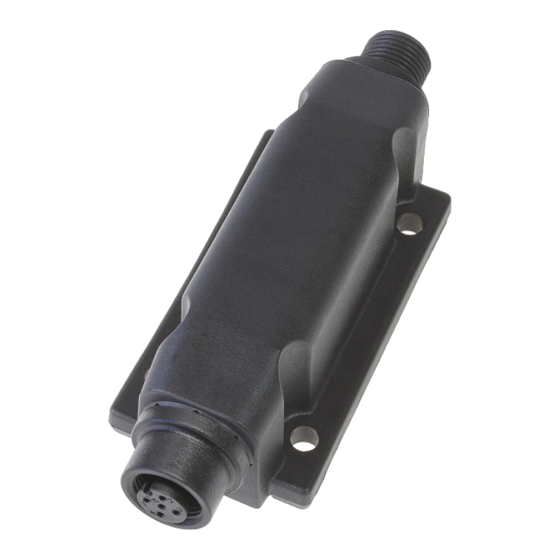
Start-Up, Operation Function The strain gauge amplifier MISG-IO has a connection for a strain gauge fullbridge. The measurement amplifier converts the signal from the application into a standardized IO-Link signal. The transmitter applies a measurement current to the strain gauge bridge with the help of its supply voltage. The output signal of the bridge changes proportional to the force change and is transmitted by the IO-Link interface as a digital signal. -
Page 6: Supply Voltage
The output signal must be proportional to the sensor signal. If this is not the case, it can be a sign of a wrong mounting position or a bad adjustment. Please read under chapter 5 Fault Recovery (p.7) for further information. Strain Gauge Amplifier IO-Link Page-6 MISG-IO-M... -
Page 7: Fault Recovery
Check for correct operation after each system change. If the fault persists, send the measuring amplifier in for repairs or replacement. In case of service: Clean devices before returning. See also chapter 6 for further details. Strain Gauge Amplifier IO-Link Page-7 MISG-IO-M... -
Page 8: Maintenance, Dismounting, Return, Cleaning, Disposal
Abrasives or corrosive solvents can damage the contacts. - Switch off and achieve complete dead-voltage condition on device before cleaning. - The sensor and IO-Link interface connected to the MISG-IO too have to be switched off and at dead-voltage condition. -
Page 9: Technical Data
Storage temperature: -20...+85 °C EMC: tested as per: EN 61000-6-2:2005 EN 61000-6-4:2007 + A1:2011 Cable length: max. 2 m (MISG-IO - sensor element) max. 20 m (MISG-IO - IO-Link master) Mechanics Casing: Material: PBT GF30 Color: Black (other colors on request) -
Page 10: Dimensions
Dimensions (in mm) top view side view front view Strain Gauge Amplifier IO-Link Page-10 MISG-IO-M... - Page 11 Strain Gauge Amplifier IO-Link Page-11 MISG-IO-M...
- Page 12 Subject to change, version 44-175 Strain Gauge Amplifier IO-Link Page-12 MISG-IO-M...
Need help?
Do you have a question about the MISG-IO and is the answer not in the manual?
Questions and answers