Table of Contents
Advertisement
Quick Links
Advertisement
Table of Contents

Related Manuals for Carver px1450


Summary of Contents for Carver px1450
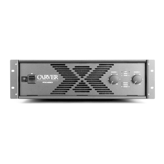
- Page 1 p x 8 5 0 / 1 4 5 0 Professional Stereo Power Amplifier...
-
Page 2: Table Of Contents
NO USER-SERVICEABLE PARTS INSIDE REFER SERVICING TO QUALIFIED SERVICE PERSONNEL Table Of Contents Introduction ...2 Unpacking and Paperwork...2 Features and Specifications PX850...3-4 PX1450...5-6 Controls and Features ...7-8 Installation and Operations Location and General Precautions ...9 Mechanical Considerations ...9 Rear Support...9 Thermal Considerations ...9 AC Power Considerations...9... -
Page 3: Introduction
F i n a l l y, take a moment to fill out and return the Warranty Registration Card packed with the amplifier and return it to Carver Professional. This will allow us to keep you informed about new products as they become available. -
Page 4: Px850
• 250W per channel into 8 ohms 425W per channel into 4 ohms 525W per channel into 2 ohms • Three connector versions available: Standard - Neutrik™ combi inputs with Binding Post outputs BR Version - Barrier Strip inputs and outputs SP Version - Neutrik™... - Page 5 BACK Continuous Average Output Power, both channels driven: (20Hz to 20kHz, with no more than 0.1% THD) 250 watts per channel into 8 ohms, 425 watts per channel into 4 ohms, 525 watts per channel into 2 ohms, Bridged-mono operation: 850 watts into 8 ohms at 1kHz, with no more than 0.1% THD...
-
Page 6: Px1450
• 375W per channel into 8 ohms 725W per channel into 4 ohms 1000W per channel into 2 ohms 1450W mono into 8 ohms 2000W mono into 4 ohms • Three connector versions available: Standard - Neutrik™ combi inputs with Binding Post outputs BR Version - Barrier Strip inputs and outputs SP Version - Neutrik™... -
Page 7: Px1450
Due to ongoing research and development, all specifications and features are subject to change without notice. Barrier strip version available. Order PX1450 Neutrik Speakon™ version available. Order PX1450SP Handle Kit available. Order PX4HK The PX1450 Series is available in 100V, 120V and 230V 50/60Hz. -
Page 8: Controls And Features
Controls And Fu n c t i o n s 1. CIRCUIT BREAKER. This protection device will trip if the line current exceeds the rating of the circuit breaker, causing the amplifier to shut down completely. This operates the same as a standard line fuse, except that it is resettable from the front panel after cooling down for a few seconds. - Page 9 10 11 8b.CH1 / CH2 INPUT CONNECTORS. 6 position barrier strip. Horizontal connection accepts 8mm spades. (see page 10 for more information). 9. FUTURE OPTION. Knockout for connector (TRS232) for external computer monitoring. 10. SIGNAL SMART THRESHOLD CONTROL. Sets desired signal level for activation of Standby circuit. (See page 12 for more information) 11.
-
Page 10: Location And General Precautions
Mechanical Considerations The PX850 and PX1450 require three rack space units (5.25”) and a depth of 15.38” inside the rack, including the rear supports. Secure the unit mechanically using four screws with washers to prevent marring the front panel. Neoprene rubber washers are a good choice because they grip the screw head and prevent them from backing out when vibrated or transported. -
Page 11: Input Sensitivity
For balanced operation: 1/4-inch phone jack: Use a 3-conductor TRS (tip-ring-sleeve) 1/4” phone plug. The tip of the plug carries the “+” (high, noninverting) side of the signal, the ring carries the “-” (low, inverting) side of the signal and the sleeve is ground (see Figure A ) . -
Page 12: Output Wiring
Output Wi r i n g (See page 17 for recommended Carver Professional A c c e s s o r i e s) . Use heavy gauge cable for speaker connections. The greater the distance between the amplifier and the speakers, the larger the diameter the cable should be to minimize power losses across the cable and improve the damping of the speaker. -
Page 13: V Distribution Systems
The PX1450 has sufficient output voltage capability in stereo mode to drive 70-volt distribution systems without using a step-up transformer at the amplifier. In this configuration, the PX1450 delivers up to 375 watts per channel to the 70-volt system, depending on the impedance of the total system. A s with all 70-volt systems, transformers are still required at each loudspeaker. -
Page 14: Operating Tips
CareandServiceAssistance C a re: Wipe off the PX850/PX1450’s front panel and chassis from time to time with a soft, dry cloth. If you have something stubborn to remove, use a mild dish soap or detergent sparingly applied to a soft cloth. Don’t use alcohol, ammonia, or other strong solvents. -
Page 15: Configurable Gain Controls
Note: The Carver P rofessional limited warranty does not extend to damage resulting from the following pro c e d u re if attempted by any person not specifically authorized by Carver P ro f e s s i o n a l To move the gain controls from the front panel to the back panel (or vice versa): 1.Unplug amplifier from power source. -
Page 16: In Case Of Difficulty
3 .Verify that the total load impedance presented to the amplifier is within the limits described in this manual for the mode of operation selected. Carver Professional reserves the right to improve its products at any time. Therefore, specifications are subject to change without notice. 15locale. -
Page 18: Accessories
For the optimum connection of your PX amplifier, here is a sample of the many accessory products available from Carver Professional. For more information on these accessories, or to receive a full-line catalog of Carver Professional Accessories, see your Authorized Carver Professional Dealer/Contractor, or contact Carver Professional at 503-978-3344.
Need help?
Do you have a question about the px1450 and is the answer not in the manual?
Questions and answers